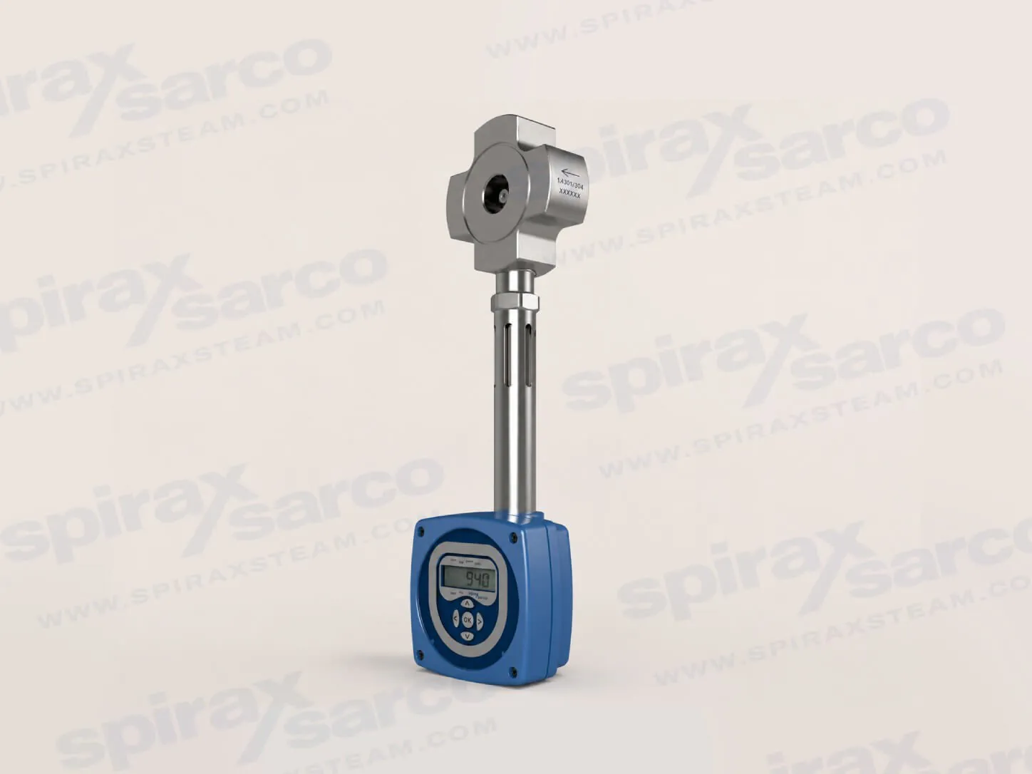
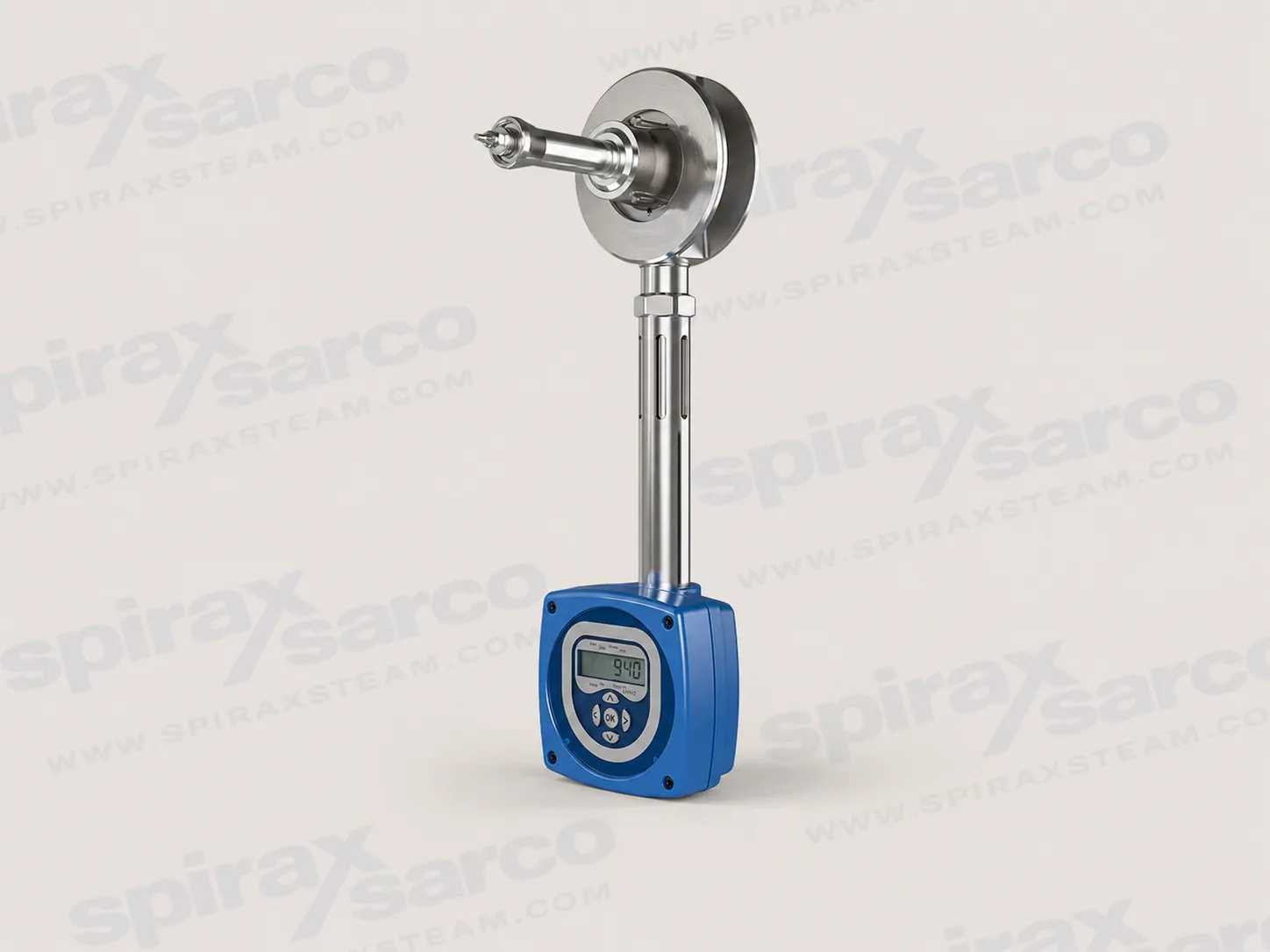
The TFA is a target-principle wafer flowmeter for saturated steam, with density-compensated mass-flow or power measurement, DN25-DN50 sizes, and RS232 or RS485 communication configurations.
TFA saturated steam flowmeter for compact steam metering
The TFA saturated steam flowmeter is a compact wafer-style meter for measuring saturated steam in smaller process and utility lines. It uses a target principle: steam flow produces a force on a fixed target, and the integrated electronics convert that signal into density-compensated mass flow or power. This approach gives a plant a direct way to make point-of-use steam consumption visible without building a measurement package around separate differential-pressure and pressure-sensing instruments.
For applications where steam demand changes with production, a simple volumetric reading can become misleading because steam density changes with pressure. The Spirax Sarco TFA is designed to compensate for that density effect inside the meter. The result is a useful measurement of mass flow, energy rate and totalised consumption for steam accountability, plant performance review and energy management. The measurement is intended for saturated steam only, so the process condition must be confirmed before the meter is selected.
The Spirax Sarco TFA saturated steam flowmeter is especially relevant when a site needs measurement on DN25 to DN50 pipework, has limited room for long instrument runs, or wants a practical first step toward sub-metering. It is a focused product for a defined duty rather than a general-purpose flowmeter for every steam condition.
Target-principle measurement in an integrated body
The target assembly sits in the steam flow and responds to the force created by the moving fluid. The electronics evaluate that force together with the operating conditions used for density compensation. Because the sensing and calculation functions are integrated into one flowmeter assembly, the installation does not need a separate pressure transmitter or differential-pressure cell solely to calculate saturated-steam mass flow. The fixed-target construction also avoids the rotating or reciprocating elements associated with some other meter types.
This design has two practical consequences for engineers. First, the meter can be used as a compact measurement point close to the steam-using equipment. Second, the selection conversation can focus on the actual line size, steam pressure range, expected minimum and maximum flow, flange standard, orientation and data interface. Those checks are more useful than treating the TFA as a generic meter and assuming that every installation arrangement will have the same performance.
Why density compensation matters in a saturated-steam system
Saturated-steam pressure and density move together as the process load changes. If a meter reports volume without applying the appropriate density relationship, the same measured volume can represent different mass flows at different pressures. That creates uncertainty when a plant is allocating steam to production areas, comparing equipment performance or checking whether an energy-saving project has delivered a real improvement.
The TFA addresses this issue by providing a density-compensated output from its integrated electronics. The front LCD can display total flow, instantaneous flow, power, pressure and temperature. A totaliser supports cumulative review, while the output can be configured for a mass-flow or power signal. The available 4-20 mA output and pulse output make the meter suitable for connection to a control system, recorder or energy-monitoring arrangement, subject to the electrical and configuration limits in the installation guide.
Where a remote display is required, the technical literature identifies the M750 display unit as an option using the linear output. Where plant data needs to be collected digitally, TFA configurations support EIA 232C (RS232C) or optional EIA 485 (RS485C) Modbus communications. The RS485 configuration has an important selection consequence: the 4-20 mA output is not available when the RS485 option is fitted. This interface decision should therefore be made before ordering, rather than treated as a commissioning change.
Performance suited to smaller saturated-steam lines
The TFA is available in DN25, DN32, DN40 and DN50 sizes, equivalent to 1 inch, 1 1/4 inch, 1 1/2 inch and 2 inch nominal pipe sizes. It is a wafer meter installed between flanges. Documented flange options include EN 1092-1 PN16, PN25 and PN40, JIS 20, KS 20, and ASME B16.5 Class 150 and Class 300. The pipe standard and internal diameter still matter: the installation guide identifies BS 1600, ASME B36.10 Schedule 40 and equivalent EN 10216-2 / EN 10216-5 pipework as the reference arrangement.
System uncertainty is stated at 95% confidence and two standard deviations in accordance with ISO 17025. From 20% to 100% of maximum rated flow, the uncertainty is plus or minus 2% of measured value. From 10% to below 20% of maximum rated flow, it is plus or minus 2% of full-scale value. The documented turndown is up to 10:1. These figures are system-level values for the complete TFA arrangement; they should be considered alongside steam pressure, expected flow range, pipework quality and the specified installation distances.
As a sizing illustration, the TI-P193-01 guide lists the following horizontal-orientation values at 10 bar g: DN25 has a guide maximum of 349 kg/h and minimum of 35 kg/h; DN32 has 572 kg/h and 57 kg/h; DN40 has 894 kg/h and 89 kg/h; and DN50 has 1,396 kg/h and 140 kg/h. These are guide values from the manufacturer's capacity table, not a substitute for confirming the project duty and allowable pressure drop.
Applications and selection boundaries
Typical reasons to consider a TFA saturated steam flowmeter include monitoring steam supplied to a process area, comparing steam use between production zones, tracking a smaller steam branch, checking the effect of insulation or control changes, and building a more useful energy picture around point-of-use equipment. The compact wafer body can be attractive where a conventional meter installation would be difficult to fit, but compactness does not remove the need for correct drainage, alignment, straight pipe and safe isolation.
The TFA should remain within its documented operating envelope. It is designed for saturated steam only and operates in one flow direction, which must match the arrow on the meter body. Below 7 bar g it can be installed in any orientation. Above 7 bar g it must be installed in a horizontal pipe with the electronics housing below the meter body; the technical sheet gives a horizontal maximum operating pressure of 32 bar g at 239 degrees C and a vertical maximum operating pressure of 7 bar g at 170 degrees C. The installation guide also limits the maximum operating pressure to 7 bar g when the electronics housing is mounted at 45 degrees or more from the vertically downward position.
Do not use the TFA as a superheated-steam meter by assumption, and do not select it for an application where a failure could compromise a strict safety-critical function. The system designer remains responsible for checking material compatibility, maximum and minimum pressure and temperature, pressure protection, condensate drainage, electrical compliance and the safeguards required by the process.
Installation-aware ordering checks
Before a quotation or purchase order is raised, confirm the TFA nominal size, flange standard and pressure class, saturated-steam pressure range, expected minimum and maximum flow, flow direction, installation orientation and communication requirement. The centralising bush kit is selected by meter size and flange type. The meter must be installed concentrically; an eccentric position, protruding gasket or intrusive weld bead can introduce measurement error.
The basic pipe arrangement requires at least 6 pipe diameters of clear straight pipe upstream and 3 diameters downstream. The upstream requirement increases to 12 diameters for documented disturbances such as two bends in different planes, a pressure-reducing valve or a partly open valve. When the meter is close coupled to rapidly acting pressure-reducing valves, the guide calls for 25 upstream diameters and 3 downstream diameters. The steam line should be properly drained, supported and aligned, and the flowmeter body and mating flanges must not be insulated because excess electronics temperature can damage the meter.
Electrical planning is equally important. The TFA is loop powered, must be earthed, and the installation guide describes a nominal 24 Vdc supply for the RS485 arrangement. The general cable length between the meter and its power supply is normally up to 300 m, subject to the total network resistance and cable capacitance; the EIA 232C link has a 15 m limit and must remain in the same area. Select the output architecture before ordering so that the required 4-20 mA, pulse, RS232 or RS485 signal is actually available in the chosen configuration.
Continue the steam flowmeter selection
Use the steam flowmeter range when the project is still comparing measurement technologies or needs a wider view of available flowmetering products. If the duty may include saturated or superheated steam over a broader pressure and load range, compare the TVA flowmeter route against the TFA boundary. When the meter must feed local display, totalisation or a wider data-integration architecture, review the available flow computers and measurement interfaces.
Choose the Spirax Sarco TFA when the verified duty is saturated steam, the DN25-DN50 wafer format fits the line, and the project benefits from an integrated density-compensated meter with a defined output and communication choice. The technical and installation information below should be read with the project piping, electrical and safety documentation before commissioning.
Description
The TFA flowmeter is designed for saturated steam only and operates on the target principle by measuring the force produced on a target by fluid flow. This force is converted into density-compensated mass flowrate or power and transmitted through a single loop-powered 4-20 mA and pulsed output. The TFA also provides a totalised flow function and EIA 232C (RS232C) or optional EIA 485 (RS485C) Modbus communications.
Sizes and pipe connections
The TFA is a wafer design available in DN25, DN32, DN40 and DN50, suitable for fitting between the following flanges:
EN 1092-1 PN16, PN25 and PN40.
Japanese Industrial Standard JIS 20 and Korean Standard KS 20.
ASME B16.5 Class 150 and Class 300.
The nominal inch sizes are 1 inch, 1 1/4 inch, 1 1/2 inch and 2 inch. Reference pipework is BS 1600, ASME B36.10 Schedule 40 or equivalent EN 10216-2 / EN 10216-5. Contact the manufacturer for systems using different pipe standards or schedules.
Maximum ambient temperature 55 °C (131 °F); maximum humidity 90% RH, non-condensing.
An M750 display unit can provide a remote display through the TFA linear output. The horizontal capacity guide includes a DN25 maximum value of 349 kg/h at 10 bar g; all capacity values are guide values and must be checked against the complete duty and pressure-drop calculation.
Performance and pressure / temperature limits
System uncertainty, at 95% confidence and two standard deviations in accordance with ISO 17025, is ±2% of measured value from 20% to 100% of maximum rated flow and ±2% of full-scale value from 10% to below 20% of maximum rated flow. Turndown is up to 10:1.
Limit
Value
Maximum design pressure
32 bar g at 239 °C (464 psi g at 462 °F).
Maximum design temperature
239 °C (462 °F).
Minimum design temperature
0 °C (32 °F), non-freezing.
Maximum operating pressure, horizontal flow
32 bar g at 239 °C (464 psi g at 462 °F).
Maximum operating pressure, vertical flow
7 bar g at 170 °C (101 psi g at 338 °F).
Minimum operating pressure
0.6 bar g (8.7 psi g).
Maximum operating temperature
239 °C (462 °F), saturated steam.
Cold hydraulic test pressure
52 bar g (754 psi g).
The pressure / temperature chart includes a software-limited region. The complete installation guides IM-P193-02 and IM-P193-03 must be checked before the meter is applied to a particular pressure, temperature and orientation.
Differential pressure drop
Differential pressure drop in mbar at percentage of maximum rated flow
Size
10%
20%
30%
40%
50%
60%
70%
80%
90%
100%
DN25
6
25
56
100
156
225
306
399
505
624
DN32
5
19
43
76
118
170
232
303
383
473
DN40
3
10
23
42
65
94
127
166
210
260
DN50
2
6
14
25
39
56
76
100
126
156
Differential pressure drop in inches H2O at percentage of maximum rated flow
Size
10%
20%
30%
40%
50%
60%
70%
80%
90%
100%
DN25
2.5
10.0
22.5
40.1
62.6
90.1
122.7
160.2
202.8
250.4
DN32
1.9
7.6
17.1
30.4
47.5
68.3
93.0
121.5
153.8
189.8
DN40
1.0
4.2
9.4
16.7
26.1
37.6
51.1
66.8
84.5
104.3
DN50
0.6
2.5
5.6
10.0
15.6
22.5
30.7
40.1
50.7
62.6
Dimensions and weights
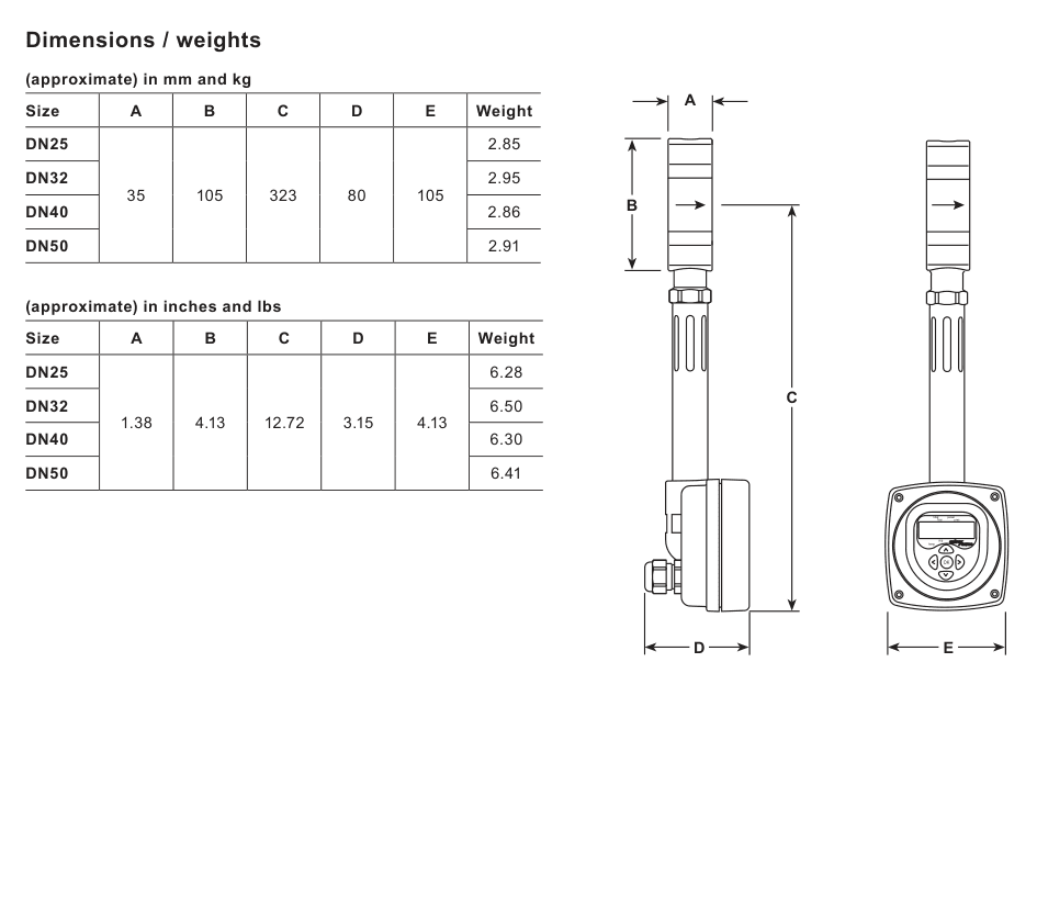
Dimensions, weights and differential pressure data reproduced from TI-P193-01, with the numerical values also structured in the tables above.
Approximate dimensions in mm and weights in kg
Size
A
B
C
D
E
Weight
DN25
35
105
323
80
105
2.85
DN32
2.95
DN40
2.86
DN50
2.91
Horizontal saturated-steam capacity guide
The following values are the manufacturer's guide values in kg/h at selected pressures. The complete source table covers the intermediate pressure points from 1 to 32 bar g. Minimum values are shown for the same size and pressure.
Size
1 bar g max / min
5 bar g max / min
10 bar g max / min
20 bar g max / min
32 bar g max / min
DN25
155 / 15
260 / 26
349 / 35
479 / 48
603 / 60
DN32
254 / 25
427 / 43
572 / 57
786 / 79
989 / 99
DN40
396 / 40
667 / 67
894 / 89
1,227 / 123
1,544 / 154
DN50
619 / 62
1,042 / 104
1,396 / 140
1,918 / 192
2,412 / 241
Centralising bush kits
Centralising bushes are required where specified by the flange arrangement. The kit must be selected for both the TFA size and the flange type. See the installation information for the fitting requirement and the effect of eccentric alignment.
Scope: This section preserves the TFA-specific installation, electrical, commissioning and maintenance requirements from IM-P193-02. It is not a substitute for the complete supplied guide or the applicable site safety procedures.
1. Safety information
The TFA is safe to operate only when it is installed, commissioned and maintained correctly by qualified personnel following the supplied instructions. General installation and safety requirements for pipework, plant construction, tools and protective equipment also apply.
Check the nameplate, technical information and intended application before installation.
The product is designed for saturated steam only. Check material suitability, pressure and temperature limits against the system.
Provide system safeguards where a product limit or a product fault could create dangerous overpressure or overtemperature.
Confirm the flow direction and install the meter concentrically in the pipe.
Do not use the TFA in applications with stringent safety requirements as the sole protective function.
Isolate pressure, discharge it safely and allow hot surfaces to cool before opening or removing the meter.
Use appropriate personal protective equipment and follow the site's permit-to-work and electrical isolation procedures.
Residual temperature hazard: At maximum permitted conditions the external surface can reach approximately 239 °C (462 °F). The product has no self-draining function; take care when removing it from a system.
Product information and storage
Before installation, check the nameplate, intended use and the published pressure, temperature and material limits. The TFA is factory tested, calibrated and inspected before shipment. If it is stored before installation, keep it between 0 °C and 55 °C (32 °F and 131 °F) with 10% to 90% relative humidity, non-condensing. The meter is designed for saturated steam only and is not intended to provide the sole protective function in a safety-critical application.
The installation guide specifies IP65 ingress protection when the correct cable glands are used. The flowmeter body is stainless steel 300 series, the internals are stainless steel 431 S29 / 300 series, the stem is stainless steel 300 series and the electronics housing is aluminium LM25.
2. Installation preparation
For steam applications, use good steam engineering practice, including a separator, correct drainage and adequate trapping. The line should be supported and aligned so that the meter is not loaded by external pipe stress. Provide working clearance for pipework, wiring, enclosure removal and reading the display. The electronics housing and internal display can be rotated for access, subject to the limits in the guide.
Do not install the TFA outdoors without additional protection against freezing. Do not lag or insulate the flowmeter body or mating flanges. Excess temperature at the electronics can invalidate the warranty, reduce performance and damage the meter.
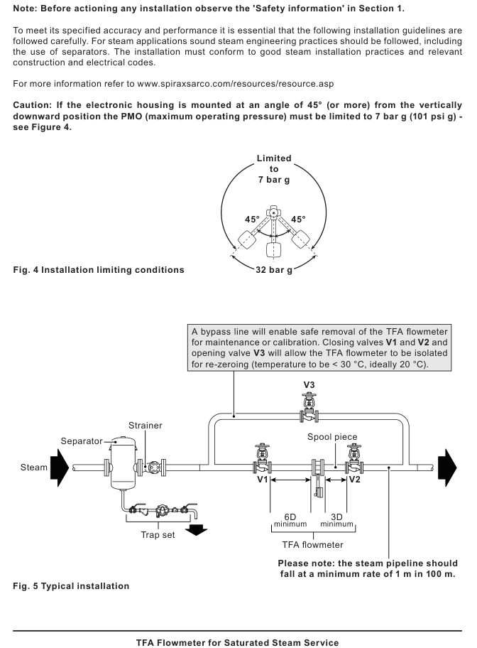
Use the bypass arrangement shown in the typical installation: close valves V1 and V2 and open V3 to isolate the flowmeter for re-zeroing, maintenance or calibration. Before isolation or removal, reduce the line temperature below 30 °C, ideally around 20 °C for re-zeroing.
Typical installation from IM-P193-02: separator and drainage upstream, a bypass for isolation, and minimum 6D upstream and 3D downstream straight pipe.
3. Orientation and flow direction
The TFA can be installed in any orientation when the pressure is below 7 bar g (101 psi g). Above 7 bar g, install it in a horizontal pipe with the electronics housing below the flowmeter body. This position also makes the display easier to read when an RS485 board is fitted. If the electronics housing is mounted at an angle of 45 degrees or more from vertically downward, the maximum operating pressure must be limited to 7 bar g.
The minimum operating pressure stated in the technical data is 0.6 bar g. Confirm the complete pressure/temperature and pressure-drop limits before selecting the installation point.
The flowmeter is for one-directional measurement only. It is not intended for bi-directional flow. The arrow on the body must match the actual direction of flow in the pipeline. Do not alter the grub screw at the rear of the target because it affects calibration, and do not loosen or remove the stem from the body.
The electronics housing can be rotated through 360 degrees for installation clearance. Use the 3 mm Allen-key screw at the rear of the housing and retighten it to 1.3 N m. Do not exceed one complete rotation, and do not loosen or remove the stem from the main body.
4. Upstream and downstream pipework
Use smooth internal pipework. Ideally use seamless pipe and avoid intrusive weld beads on the internal diameter. For the reference pipe standards, nominal diameters of 25 mm, 32 mm, 40 mm and 50 mm correspond to internal diameters of 27 mm, 35 mm, 41 mm and 52 mm respectively for DN25, DN32, DN40 and DN50.
Allow a minimum of 6D clear straight pipe upstream and 3D downstream in the basic arrangement.
If there is an upstream diameter increase, use 12D upstream.
Where two 90 degree bends are upstream in different planes, or a pressure-reducing valve or partly open valve is upstream, use 12D upstream.
Avoid a rapidly cycling actuated valve immediately downstream. Where rapid-acting pressure-reducing valves are close coupled, allow at least 25D upstream and 3D downstream.
Keep gaskets clear of the bore. A gasket projecting into the pipe can create inaccurate readings.
For horizontal steam pipework, provide drainage and a fall of at least 1 m in 100 m in the direction shown by the installation arrangement. The guide's fault-finding section also refers to a fall of 1 in every 70-100 m when investigating condensate-related false flow; confirm the detailed slope against the complete guide and the site's steam engineering design. Use eccentric reducers for line-size changes where required by the steam installation arrangement. Keep safety valves as far from the flowmeter as possible, with at least 25D separation.
5. Centralising bushes and mechanical alignment
Use the centralising bush kit selected for the TFA size and flange type. The bushes fit over the lower two flange bolts and use the meter's own weight to centre it. Correct centring is essential: eccentricity between the meter, gasket and pipe can cause measurement errors. Confirm the selected kit against TI-P193-01 before ordering.
After the meter is fitted, check that the body, stem and electronics enclosure have sufficient clearance and that the pipe supports do not impose strain. Do not change the target adjustment setting. Before any removal for maintenance or re-zeroing, isolate the meter using the valves and bypass arrangement, confirm that pressure is released and ensure the temperature is below 30 °C, ideally around 20 °C for re-zeroing.
6. Electrical installation
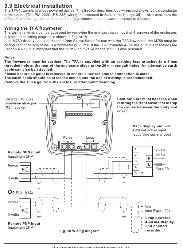
The TFA is loop powered. Access the terminals by removing the enclosure end cap with its four screws. The flowmeter must be earthed using the supplied lead or an alternative earth cable connected to the threaded earth point. Remove paint from the connection area to keep earth resistance low; the guide recommends an earth cable of at least 4 mm2 and a crimped connection.
A nominal 24 Vdc supply is needed for the flowmeter and the operating range depends on loop resistance. The general supply operating range is 9-28 Vdc; the RS485 board uses 24 Vdc (19-28 Vdc, 50 mA maximum). The general maximum cable length between the flowmeter and the power supply is normally 300 m, but the actual limit depends on network devices, total resistance and cable capacitance. Use suitable shielded twisted-pair cable and follow the power-supply manufacturer's installation requirements.
Typical loop, pulse, remote input and EIA 232 wiring arrangement from IM-P193-02. The complete guide must be followed for terminal work.
With the RS485 board fitted, the unit uses a 24 Vdc supply and RS485 data terminals. The RS232 and 4-20 mA functions are not available in this configuration. The EIA 232C link uses an RJ11 socket and is limited to 15 m; it must remain in the same area as the flowmeter. The enclosure cable entry is M20 x 1.5 via gland, and glands suitable for EN 50262 / IP68 are recommended. The gland/body and gland-nut torque settings are 5 N m. Modbus communications require the correct converter or host interface and matching baud rate and address settings.
The earth connection uses a 4 mm threaded hole near the 20 mm conduit holes. Remove paint at the connection, use an earth cable of at least 4 mm2 and use a crimped connection where appropriate. If an M750 remote display is used, configure its 20 mA input to the TFA flowmeter's selected range. Remove the enclosure silica gel after commissioning.
7. Commissioning and operation
Commission the flowmeter with the process fluid isolated as described in the guide. The display is factory set to metric units. Commissioning is performed through the five-button LCD display unit, and settings are stored in non-volatile memory. The display can show total flow, instantaneous flow, power, pressure and temperature. The display front panel can be rotated through 180 degrees for access. A 9 V PP3 battery may be connected to the 4-20 mA loop to configure an uninstalled meter, but the meter must still be zeroed in-line and its operation checked.
For zeroing, close the isolation valves so that no flow passes through the meter. The pipe temperature should be above 5 °C and below 30 °C, ideally 20 °C. The guide recommends a zero adjustment at least every 12 months to remove long-term electronic zero drift. If the zero procedure reports an error, confirm that flow is stopped and that the temperature is within the permitted range before repeating the procedure.
Output settings allow the 4-20 mA source to represent flow or power and allow pulse output testing. Pulse output can represent total mass or energy, with a configurable pulse value and a pulse width from 0.02 to 0.2 seconds. The display and transmitted units can be metric (kg/h, kW, bar g and °C) or imperial (lb/h, MBtu/h, psi g and °F). Configure the communication type as ASCII or Modbus, select 1200 or 9600 baud and set a matching Modbus address from 001 to 255. The RS485 option must not be wired as though it were a 4-20 mA loop.
The basic-data settings include dryness fraction and atmospheric pressure compensation; the factory settings table records 100% dryness fraction, metric units, 1.01 bar a atmospheric pressure, pulse output on, one pulse per kg and a 50 ms pulse width. The totaliser is backed up every eight minutes, so a power interruption can lose up to eight minutes of totalised steam.
8. Maintenance and fault finding
The display includes diagnostic functions and operating errors can be shown on the display or signalled through the configured output. Before replacing electronics or a display, isolate power, observe electrostatic discharge precautions and avoid operating the electronics without the sensor installed. Replacement electronic assemblies should be ordered using the flowmeter serial number.
Recalibration frequency depends on the instrument conditions and application. The guide gives a typical recalibration interval of 2 to 5 years, in addition to the annual zero adjustment. If readings are inaccurate, check centring, gasket projection, pipe-bore irregularities, flow direction, upstream and downstream lengths and the presence of wet or two-phase steam; wet steam should be separated before measurement. After installation or maintenance, confirm the complete system function and test alarms or protective devices before returning the steam line to normal service.