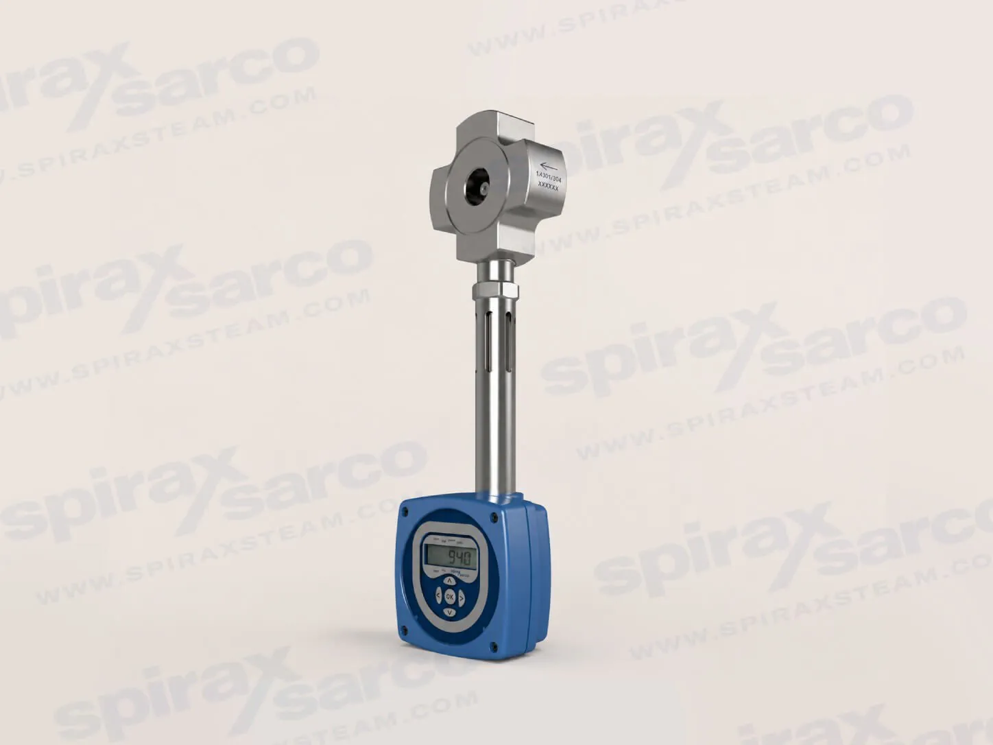
TFA Saturated Steam Flowmeter
The TFA is a target-principle wafer flowmeter for saturated steam, with density-compensated mass-flow or power measurement, DN25-DN50 sizes, and RS232 or RS485 communication configurations.

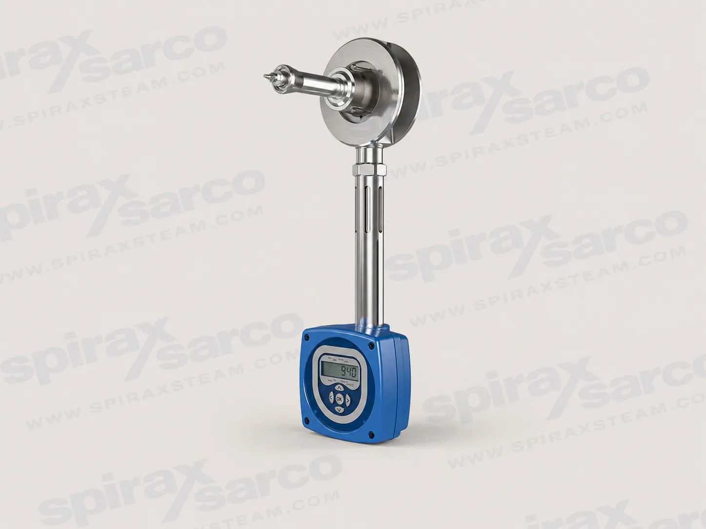
TVA-FLOWMETERS
TVA Steam Flowmeter
Integrated target-type flowmeter for saturated steam and, with the dedicated pressure sensor kit, superheated steam. Density compensation, local display, totalisation, 4-20 mA, pulse and Modbus communication support are combined in one wafer-mounted instrument.
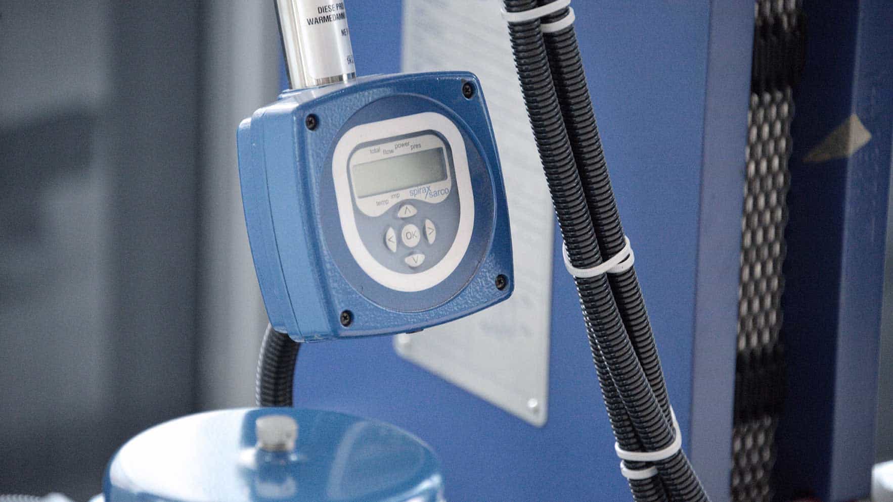
The Spirax Sarco TVA flowmeter is an integrated target-type instrument for measuring steam flow across a wide operating range. It is designed for saturated steam and can be used for superheated steam when the dedicated pressure sensor kit is selected. The TVA flowmeter converts the force generated on a moving cone by the steam into a density-compensated mass-flow signal. This gives the plant a direct measurement of mass flow rather than a simple velocity indication, while the local display can show flow, totalised flow, pressure and temperature data.
The TVA is intended for projects where steam consumption must be measured as a complete operating range, including lower loads that are often missed by a narrow-range meter. The official product information states turndown up to 50:1 at best-practice steam velocities. That range supports steam-accounting, energy management, boiler-house monitoring and process-load comparison, but the final selection still depends on actual minimum and maximum flow, pressure, pipe geometry and the required installation orientation.
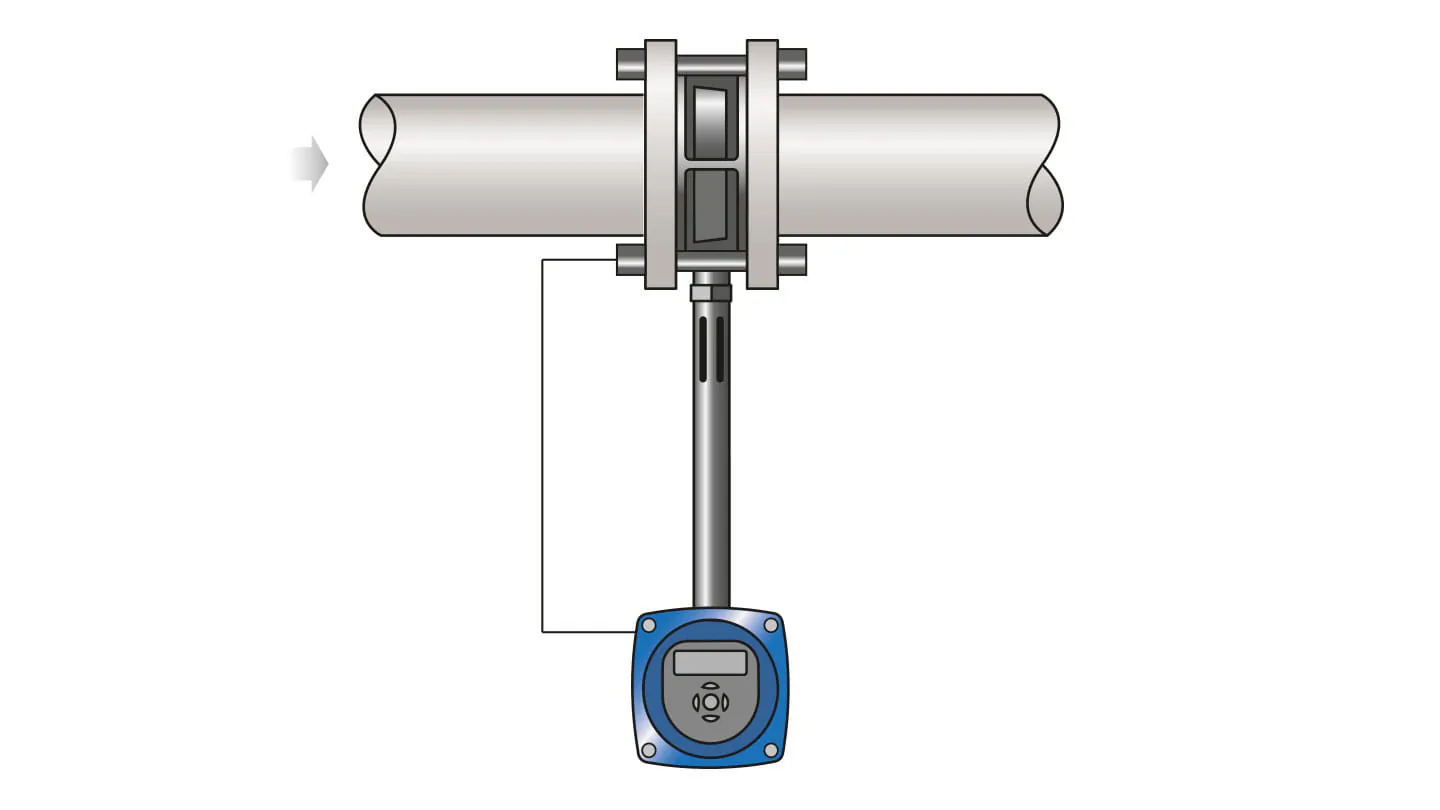
Steam passes through the wafer body and acts on the profiled moving cone. The resulting force is measured by the sensing assembly and processed by the integrated electronics. A built-in temperature measurement is used for density compensation, allowing the instrument to calculate and transmit mass flow. The unit also provides a totalised-flow function, so a control system can use both an instantaneous value and an accumulated consumption value.
This integrated architecture reduces the number of separate pressure tappings and transmitters needed for a basic saturated-steam measurement package. It also gives the operator a local LCD interface for commissioning and day-to-day checks. A remote M750 display can be connected through the linear output where a control-room or panel indication is needed.
The Spirax Sarco TVA flowmeter provides a loop-powered 4-20 mA output proportional to mass flow and a pulse output for totalisation or a compatible counter. The current official product page also lists EIA 232C (RS232) or EIA 485C (RS485) Modbus communications. The older installation manual gives detailed RS232 wiring and a 15 m maximum communication length; it does not provide the wiring or limits for the current RS485 statement. Engineers should therefore confirm the required communication option and the matching project documentation before ordering.
Nominal power is 24 Vdc, with the companion installation manual specifying a 9-28 Vdc operating range. The electrical installation uses M20 x 1.5 entries and the guide recommends shielded twisted-pair wiring. These details matter when the flowmeter is being integrated into an existing energy-management or distributed-control system: confirm loop resistance, cable routing, signal isolation and the destination of the pulse output before finalising the panel design.
The TVA can deliver a broad measurement range only when the steam line presents a stable, well-conditioned flow profile. The technical information calls for at least 6 straight pipe diameters upstream and 3 downstream, with no valves, fittings or cross-sectional changes in those base lengths. A diameter increase upstream, two bends in different planes, a pressure-reducing valve or a partly open valve can require 12 upstream diameters. These are selection inputs, not optional finishing details, because the meter must be installed concentrically and the internal pipe bore must remain smooth.
Steam quality is equally important. The installation documents call for sound steam engineering practice, including correct line drainage, a separator where wet steam is present and a suitable trap set. Bi-phase flow is not permitted for accurate measurement; moisture droplets should be removed before the steam reaches the flowmeter. The TVA body and mating flanges must not be insulated because heat can raise the electronics temperature above its limit. Leave clearance for cable installation, end-cap removal and display viewing, and provide a bypass where safe removal for calibration or maintenance is required.
Mass flow and totalised flow serve different plant decisions. The instantaneous output can be compared with process demand, boiler load or a control-system setpoint, while the totalised value can support shift, batch or building-level consumption checks. The local display also exposes operating data for commissioning and fault checks. If remote indication is required, the M750 display option can use the 4-20 mA signal, subject to the wiring and scaling conditions in the installation manual.
At commissioning, the flowmeter should be zeroed with the flow isolated and the unit at the temperature specified by the installation instructions. The full manual recommends zeroing at least once a year and says recalibration is typically needed every 2 to 5 years depending on service conditions. Those are maintenance planning references rather than a substitute for an application-specific calibration interval. Keep the complete IM-P337-51 manual available to the commissioning and maintenance team.
The Spirax Sarco TVA flowmeter fits duties where the project needs density-compensated mass flow, totalisation or direct control-system signals in one instrument. Saturated-steam duties should be checked against the published pressure and temperature envelope. Superheated-steam duties require the dedicated pressure sensor kit and a separate review of the applicable sizing and pressure conditions; the saturated-steam tables in the technical sheet must not be reused as superheated-steam limits.
The TVA is a wafer design available in DN50, DN80 and DN100 in the companion installation documentation. The US technical sheet presents the same product family using 2, 3 and 4 inch size labels and gives capacities for the specified saturated-steam conditions. Choose the flange standard and rating from the actual pipe specification. The installation manual lists EN 1092 PN16, PN25 and PN40, BS 10 Table H, ASME/ANSI B16.5 Class 150 and 300, and Korean KS 20; the US technical sheet specifically details ASME/ANSI B16.5 Class 150 and 300.
Confirm whether the medium is saturated or superheated steam. For superheated steam, include the dedicated pressure sensor kit in the application review.
Provide minimum and maximum flow, operating pressure, expected temperature and the required measurement orientation. The published saturated-steam performance is +/-2% of reading from 10% to 100% of maximum rated flow and +/-0.2% FSD from 2% to 10%, at 95% confidence to 2 standard deviations.
Check that the pipe bore, flange standard and pressure class match the selected size. Keep at least 6 straight pipe diameters upstream and 3 downstream; the technical documents require longer upstream lengths for specified disturbances and diameter changes.
Confirm space for the enclosure, display viewing, cable entries and safe isolation. Above 7 barg, the installation manual requires horizontal pipework with the electronics housing below the body; below 7 barg the flowmeter can be installed in any orientation within the stated limits.
Plan drainage and steam conditioning. A separator and suitable trap set are part of good steam engineering practice, and the flowmeter body and mating flanges must not be insulated because heat can damage the electronics.
For the wider target flowmeter range, compare the available target-principle products and their service boundaries. The broader flowmetering portfolio is useful when the project is still comparing measurement technologies. If the duty is limited to saturated steam and a different target-meter configuration is being considered, review the TFA saturated steam flowmeter. For remote indication, totalisation or signal integration, review compatible flowmetering computers and indicators.
Before purchase, provide the operating data and pipe details rather than selecting from nominal size alone. The technical information and installation documents below contain the source tables, wiring conditions, installation constraints and maintenance references needed for the final engineering review.
The TVA flowmeter is designed for saturated steam and operates on the target principle by measuring the force produced on a moving cone by the fluid flow. This strain is converted into a density-compensated mass flowrate and transmitted through a single loop-powered 4-20 mA output and a pulse output. The TVA also incorporates a totalised-flow function and RS232 Modbus communications in this technical sheet.
Sizes are 2, 3 and 4 inch. The TVA is a wafer design suitable for fitting between ASME (ANSI) B16.5 Class 150 and Class 300 flanges. The flowmeter should be installed in pipework manufactured to BS 1600 or ASME (ANSI) B 36.10 Schedule 40 (ASME B 36.10). For a different pipe standard or schedule, use suitable Schedule 40 spool pieces or contact Spirax Sarco.
Condition | Limit |
|---|---|
Maximum design pressure | 464 psig at 462 F (462°F) |
Maximum design and operating temperature | 462 F (462°F) saturated steam |
Minimum design and operating temperature | 32 F (32°F) |
Maximum operating pressure, horizontal flow | 464 psig at 462 F (462 °F) |
Maximum operating pressure, vertical flow | 101 psig at 338 F |
Minimum operating pressure | 9 psig |
Maximum electronics ambient temperature | 131 F (131°F) |
Maximum electronics humidity | 90% RH, non-condensing |
Cold hydraulic test pressure | 754 psig |
Local regulations may restrict use below the stated conditions. The pressure and temperature limits in this sheet are for the saturated-steam service described here. For full details see the Installation and Maintenance Instructions IM-P337-51 and IM-P337-52. The optional M750 display unit is described in the relevant M750 literature. Issue reference: TI-P337-50-US 04.11.
Item | Data |
|---|---|
IP rating | IP65 with correct cable glands |
Power supply | Loop powered, nominal 24 Vdc |
Outputs | 4-20 mA proportional to mass flow; pulse output, Vmax 28 Vdc and Rmin 10 kOhm |
Communication port | Modbus EIA 232C (RS232) |
System uncertainty | +/-2% of measured value from 10% to 100% of maximum rated flow; +/-0.2% FSD from 2% to 10% of maximum rated flow, at 95% confidence to 2 standard deviations in accordance with ISO 17025 |
Turndown | Up to 50:1 |
Component | Material |
|---|---|
Flowmeter body | Stainless steel S316, 1.4408 CF8M |
Internals | 431 S29, S303, S304 or S316 |
Spring | Inconel X750 or equivalent |
Flowmeter stem | Stainless steel, 300 series |
Electronics housing | Aluminium LM25 |
Approximate dimensions are in inches and pounds.
Size | A | B | C | D | E | Weight |
|---|---|---|---|---|---|---|
2 in | 1.4 | 4.1 | 12.7 | 6.3 | 2.6 | 5.9 lb |
3 in | 1.8 | 5.4 | 13.1 | 6.3 | 2.6 | 9.7 lb |
4 in | 2.4 | 6.4 | 13.5 | 8.5 | 2.6 | 16.0 lb |
Flowmeter size | Maximum flow, US gal/min | Maximum pressure drop, inches water gauge |
|---|---|---|
2 in | 80 | 300 |
3 in | 203 | 200 |
4 in | 317 | 200 |
Maximum and minimum flowrates below are guide values for horizontal orientation at the listed saturated-steam pressures. Maximum values are calculated at maximum differential pressure. Contact Spirax Sarco for vertical capacities.
Size | Flow | 15 psig | 44 psig | 73 psig | 102 psig | 145 psig | 174 psig | 218 psig | 290 psig | 363 psig | 435 psig | 464 psig | Unit |
|---|---|---|---|---|---|---|---|---|---|---|---|---|---|
2 in | Maximum | 1,365 | 1,894 | 2,297 | 2,637 | 3,075 | 3,336 | 3,695 | 4,228 | 4,707 | 5,148 | 5,311 | lb/hr |
2 in | Minimum | 26 | 37 | 46 | 53 | 62 | 66 | 73 | 84 | 95 | 104 | 132 | lb/hr |
3 in | Maximum | 3,501 | 4,859 | 5,895 | 6,768 | 7,895 | 8,565 | 9,482 | 10,851 | 12,081 | 13,215 | 13,633 | lb/hr |
3 in | Minimum | 71 | 97 | 117 | 134 | 159 | 172 | 190 | 216 | 243 | 265 | 284 | lb/hr |
4 in | Maximum | 5,456 | 7,573 | 9,187 | 10,547 | 12,304 | 13,347 | 14,778 | 16,912 | 18,827 | 20,593 | 21,246 | lb/hr |
4 in | Minimum | 108 | 152 | 183 | 212 | 247 | 267 | 295 | 337 | 377 | 412 | 425 | lb/hr |
Provide at least 6 straight pipe diameters upstream and 3 downstream. Do not place valves, fittings or cross-sectional changes within these base lengths.
Increase the upstream straight length to 12 diameters where the pipe diameter increases upstream, or where the listed bends, pressure-reducing-valve or partly open-valve conditions apply.
Keep upstream and downstream pipe bores smooth and install the TVA concentrically. The flowmeter can be installed in any orientation up to a line pressure of 101 psig.
Use correct drainage, pipe support and eccentric reducers for steam service. Do not insulate the TVA body or mating flanges.
This guide must be read with the Installation and Maintenance Instructions IM-P337-51. It highlights the minimum installation requirements needed for the TVA flowmeter to perform as expected.
The electronics housing can be rotated through 270 degrees to provide clearance for installation. Carefully remove the four end-cap screws, support the end cap and loosen, but do not remove, the end-cap lock screw. Rotate the electronics housing to the required position, retighten the lock screw to 3 N m (26.5 lbf in), and replace the end cap and four screws.
Do not loosen or remove the grub screw next to the lock screw. Do not loosen or remove the stem from the main body of the unit.
A bypass line allows safe removal of the flowmeter for maintenance or calibration. Closing isolation valves V1 and V2 and opening valve V3 isolates the TVA for re-zeroing; the temperature should be below 20 C (20°C) before re-zeroing. The horizontal installation arrangement includes a maximum 3m spool-piece condition where shown in the guide.
Installation condition | Requirement |
|---|---|
Base straight pipe | 6D minimum upstream and 3D minimum downstream of clear pipework. |
Flow direction | Follow the marked direction of flow and keep the unit concentric with the pipe. |
Pressure above 7 barg | Install in horizontal pipework with the electronics housing below the flowmeter body. |
Pressure below 7 barg | Any orientation is permitted within the published limits. |
Pipe and insulation | Use suitable pipe alignment and do not insulate the TVA flowmeter or its mating flanges. |
For a full installation review, account for the pipe diameter, flange alignment, separator, strainer, trap set, bypass isolation and the available clearance for wiring and display viewing. The electronics housing and display can be rotated, but the enclosure must remain within its temperature limits.
The TVA is loop powered. Use a nominal 24 Vdc supply within the 9-28 Vdc operating range. The guide specifies 0.5 mm2 cable and a maximum length of 300 m. The pulse output supports a maximum of 28 Vdc; a remote input must be compatible with the stated load conditions. The loop output can feed a display unit or chart recorder, and the unit provides an EIA 232 (RS232) communication port through an RJ11 socket.
Connection or condition | Guide value |
|---|---|
Supply | 9-28 Vdc; nominal 24 Vdc |
Cable size | 0.5 mm2 |
Maximum cable length | 300 m, subject to total resistance and cable capacitance |
Pulse output | Maximum 28 Vdc; use a compatible load and observe the wiring diagram |
Remote display | M750 display unit through the 4-20 mA loop output; configure the remote display to the TVA flow at 20 mA |
Communication | EIA 232 (RS232), RJ11 socket; see IM-P337-51 for detailed wiring |
After the mechanical and electrical work is complete, proceed to the programming and commissioning section of IM-P337-51. Verify the flow direction, isolation and alarm arrangements, then check the 4-20 mA and pulse signals under controlled conditions. The full manual contains the safety information, commissioning menus, operating instructions, maintenance procedure and fault-finding guidance that remain the final reference for the installed product.
Compare the meter, steam duty and plant-data requirements before finalising the flowmetering package.
Review compact target-type meters when the project still requires a broader product comparison.
Review the TFA meter when the duty is limited to saturated steam measurement.
Add indication, totalisation or signal integration with compatible flowmetering computers.