Purga de aire, pérdidas de calor y resumen de diversas normas relacionadas con tuberías
La purga de aire y otros gases incondensables de los sistemas de vapor, y la provisión de aislamiento adecuado, son vitales para garantizar la eficiencia, seguridad y rendimiento de la planta de vapor.
Air venting
Purga de aire
Cuando el vapor se admite por primera vez en una tubería después de un período de inactividad, la tubería está llena de aire. Cantidades adicionales de aire y otros gases no condensables entrarán con el vapor, aunque las proporciones de estos gases son normalmente muy pequeñas en comparación con el vapor. Cuando el vapor se condensa, estos gases se acumularán en las tuberías e intercambiadores de calor. Se deben tomar precauciones para descargarlos. La consecuencia de no eliminar el aire es un período prolongado de calentamiento, y una reducción en la eficiencia de la planta y el rendimiento del proceso. El aire en un sistema de vapor también afectará la temperatura del sistema. El aire ejercerá su propia presión dentro del sistema, y se sumará a la presión del vapor para dar una presión total. Por lo tanto, la presión real del vapor y la temperatura de la mezcla vapor/aire serán inferiores a las sugeridas por un manómetro. De mayor importancia es el efecto que el aire tiene sobre la transferencia de calor. Una capa de aire de solo 1 mm de grosor puede ofrecer la misma resistencia al calor que una capa de agua de 25 μm de grosor, una capa de hierro de 2 mm de grosor o una capa de cobre de 15 mm de grosor. Es muy importante, por tanto, eliminar el aire de cualquier sistema de vapor. Las ventilas de aire automáticas para sistemas de vapor (que funcionan según el mismo principio que las purgas de vapor termostáticas) deben instalarse por encima del nivel de condensado para que solo el aire o las mezclas vapor/aire puedan alcanzarlas. La mejor ubicación para ellas es al final de los conductos principales de vapor como se muestra en la Figura 10.5.1. La descarga de una ventila de aire debe canalizarse a un lugar seguro. En la práctica, una línea de condensado que desciende hacia un receptor ventilado puede aceptar la descarga de una ventila de aire.
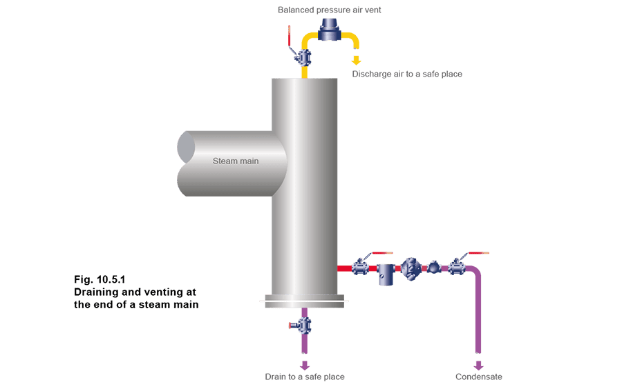
La descarga de una ventila de aire debe canalizarse a un lugar seguro. En la práctica, una línea de condensado que desciende hacia un receptor ventilado puede aceptar la descarga de una ventila de aire.
Además de la purga de aire al final de un conducto principal, también deben instalarse ventilas de aire:
- En paralelo con una purga de balde invertido o, en algunos casos, una purga termodinámica. Estas purgas a veces son lentas para ventilar aire en el arranque.
- En espacios de vapor difíciles (como en el lado opuesto a donde el vapor entra en una cuba camisada).
- Donde hay un gran espacio de vapor (como un autoclave), y una mezcla vapor/aire podría afectar la calidad del proceso.
Reduction of heat losses
Reducción de pérdidas de calor
Incluso cuando un conducto principal de vapor se ha calentado, el vapor continuará condensándose a medida que se pierde calor por radiación. La tasa de condensación dependerá de la temperatura del vapor, la temperatura ambiente y la eficiencia del aislamiento de la tubería. Para que un sistema de distribución de vapor sea eficiente, deben tomarse medidas apropiadas para asegurar que las pérdidas de calor se reduzcan al mínimo económico. El espesor más económico de aislamiento dependerá de varios factores:
- Costo de instalación.
- El calor transportado por el vapor.
- Tamaño de la tubería.
- Temperatura de la tubería. Al aislar tuberías externas, se debe tener en cuenta la humedad y la velocidad del viento. The effectiveness of most insulation materials depends on minute air cells which are held in a matrix of inert material such as mineral wool, fibreglass or calcium silicate. Typical installations use aluminium clad fibreglass, aluminium clad mineral wool and calcium silicate. It is important that insulating material is not crushed or allowed to waterlog. Adequate mechanical protection and waterproofing are essential, especially in outdoor locations. The heat loss from a steam pipe to water, or to wet insulation, can be as much as 50 times greater than from the same pipe to air. Particular care should be taken to protect steam lines, running through waterlogged ground, or in ducts, which may be subjected to flooding. The same applies to protecting the lagging from damage by ladders etc., to avoid the ingress of rainwater. It is important to insulate all hot parts of the system with the exception of safety valves. This includes all flanged joints on the mains, and also the valves and other fittings. It was, at one time, common to cut back the insulation at each side of a flanged joint, to leave access to the bolts for maintenance purposes. This is equivalent to leaving about 0.5 m of bare pipe. Fortunately, prefabricated insulating covers for flanged joints and valves are now more widely available. These are usually provided with fasteners so that they can readily be detached to provide access for maintenance purposes.
Calculation of heat transfer
Calculation of heat transfer
The calculation of heat losses from pipes can be very complex and time consuming, and assume that obscure data concerning pipe wall thickness, heat transfer coefficients and various derived constants are easily available, which, usually, they are not. The derivations of these formulae are outside the scope of this Module, but further information can be readily found in any good thermodynamics textbook. To add to this, an abundance of contemporary computer software is available for the discerning engineer. This being so, pipe heat losses can easily be found by reference to Table 10.5.1 and a simple equation (Equation 2.12.2). The table assumes ambient conditions of between 10 - 21°C, and considers heat losses from bare horizontal pipes of different sizes with steam contained at various pressures.
Table 10.5.1 Heat emission from pipes
Table 10.5.1 Heat emission from pipes
Note: Heat emission from bare horizontal pipes with ambient temperatures between 10°C and 20°C and still air conditions
| Temperature difference steam to air °C | Pipe size (DN) | |||||||||
| 15 | 20 | 25 | 32 | 40 | 50 | 65 | 80 | 100 | 150 | |
| W/m | ||||||||||
| 60 | 60 | 72 | 88 | 111 | 125 | 145 | 172 | 210 | 250 | 351 |
| 70 | 72 | 87 | 106 | 132 | 147 | 177 | 209 | 253 | 311 | 432 |
| 80 | 86 | 104 | 125 | 155 | 174 | 212 | 248 | 298 | 376 | 519 |
| 90 | 100 | 121 | 146 | 180 | 203 | 248 | 291 | 347 | 443 | 610 |
| 100 | 116 | 140 | 169 | 207 | 233 | 287 | 336 | 400 | 514 | 706 |
| 110 | 132 | 160 | 193 | 237 | 267 | 328 | 385 | 457 | 587 | 807 |
| 120 | 149 | 181 | 219 | 268 | 302 | 371 | 436 | 517 | 664 | 914 |
| 130 | 168 | 203 | 247 | 301 | 342 | 417 | 490 | 581 | 743 | 1 025 |
| 140 | 187 | 226 | 276 | 337 | 382 | 464 | 547 | 649 | 825 | 1 142 |
| 150 | 208 | 250 | 306 | 374 | 424 | 514 | 607 | 720 | 911 | 1 263 |
| 160 | 229 | 276 | 338 | 413 | 469 | 566 | 670 | 794 | 999 | 1 390 |
| 170 | 251 | 302 | 372 | 455 | 515 | 620 | 736 | 873 | 1 090 | 1 521 |
| 180 | 275 | 330 | 407 | 499 | 566 | 676 | 805 | 955 | 1 184 | 1 658 |
| 190 | 299 | 359 | 444 | 544 | 615 | 735 | 877 | 1041 | 1 281 | 1 800 |
| 200 | 325 | 389 | 483 | 592 | 681 | 795 | 951 | 1 130 | 1 381 | 1 947 |
Other factors can be included in the equation, for instance, if a pipe is lagged with insulation providing a reduction in heat losses to 10% of the uninsulated pipe, then it is multiplied by a factor of 0.1.
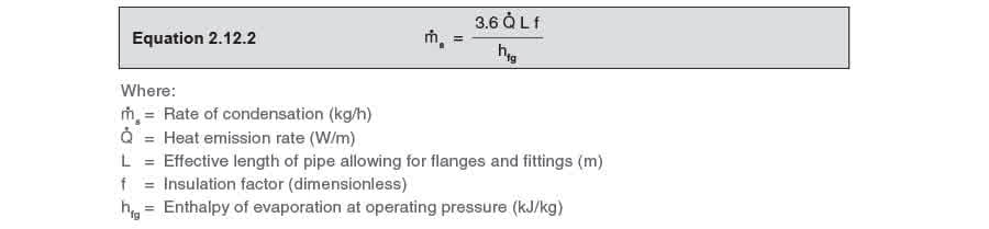
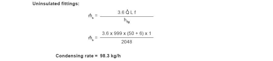
Note: The constant 3.6 gives the answer in kg/h Equivalent lengths:
- Pair of mating flanges 0.5 m
- Line size valve 1.0 m Example 10.5.1 50 m of 100 mm pipe has 8 pairs of flanges and two valves, and carries saturated steam at 7 bar g. Ambient temperature is 10°C, and the insulation efficiency is given as 0.1 With reference to Table 10.5.1 and the application of Equation 10.5.1: determine the quantity of steam that will be condensed per hour: Part 1 - Without insulation. Part 2 - With the pipe insulated, but the valves and flanges are left without insulation. Part 3 - Completely insulated. Equivalent length of fittings:
- (8 pairs of flanges @ 0.5 m) + (2 valves @ 1.0 m) = 6.0 m of pipe
- Saturated steam at 7 bar g:

Part 1 - Without insulation:
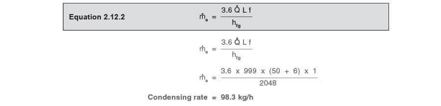
Part 2 - Pipe insulated, but without insulation on the valves and flanges: Consider the two elements separately:
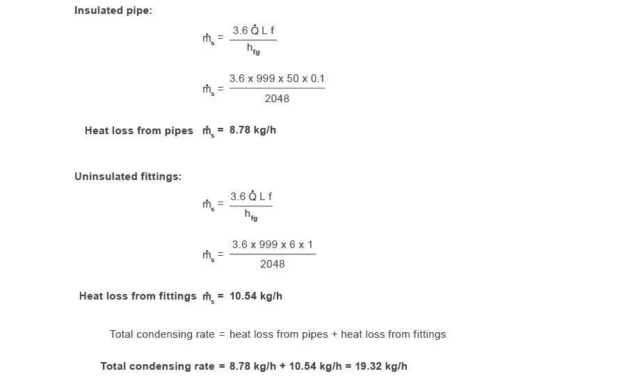
Part 3 - Pipe and fittings insulated:
Relevant UK and International Standards
Relevant UK and International Standards
Symbols have been used to indicate, technically equivalent standards (=), and related standards (≠) respectively.
Table 10.5.2
Table 10.5.2
| BS 10 | Specification for flanges and bolting for pipes, valves and fittings. |
| BS 21 = ISO 7/1 ≠ ISO 7/2 | Specification for pipe threads for tubes and fittings where pressure tight joints are made on the threads. |
| EN 13480 | Specification for metallic industrial piping. |
| BS 1306 | Specification for copper and copper alloy piping systems. |
| EN 10255 | Specification for screwed and socketed tubes and tubulars and for plain end steel tubes suitable for welding and screwing to BS 21 pipe threads. |
| BS 1560 | Circular flanges for pipes, valves and fittings (Class designated): - Part 3, Section 3.1 - Specification for steel flanges (≠ ISO 7005). - Part 3, Section 3.2 - Specification for cast iron flanges (≠ ISO 7005-2). - Part 3, Section 3.3 - Specification for copper alloy and composite flanges (≠ ISO 7005-3). |
| BS 1600 | Dimensions of steel pipe for the petroleum industry. |
| EN 10253-1 | Specification for butt welding pipe fittings for pressure purposes. |
| BS 1710 | Specification for identification of pipelines. |
| BS 2779= IS0 228/1, ISO 228/2 | Specification for pipe threads for tubes and fittings where pressure tight joints are not made on the threads. |
| EN 10220 | Specification for dimensions and masses per unit length of welded and seamless steel pipes and tubes for pressure purposes. |
| BS 3601 | Specification for steel pipes and tubes with specified room temperature properties for pressure purposes. |
| EN 10216-2 EN 10217-2/3/5 | Specification for steel pipes and tubes for pressure purposes: carbon and carbon manganese steel with specified elevated temperature properties. |
| EN 10216-4 EN 10217-4 | Specification for carbon and alloy steel pipes and tubes with specified low temperature properties for pressure purposes. |
| EN 10216-2 EN 10217-2 BS 3604-2 | Steel pipes and tubes for pressure purposes: ferritic alloy steel with specified elevated temperature properties. |
| BS 3605-1/2 | Austenitic stainless steel pipes and tubes for pressure purposes. |
| BS 3799 | Specification for steel pipe fittings, screwed and socket welded for the petroleum industry. |
| BS 3974 | Specification for pipe supports. |
| EN 1092-1 | 3.1 - Specification for steel flanges; |
| EN 1092-2 | 3.2 - Specification for cast iron flanges (≠ ISO 7005-2); |
| BS 4504 | 3.3 - Specification for copper alloy and composite flanges (≠ ISO 7005-3). |
Summary
Summary
To summarise the ‘Steam Distribution’ Block of The Steam and Condensate Loop, the following checklist may be used to ensure that a steam distribution system will operate efficiently and effectively: