Atuadores e Positioners de Válvulas de Controle
Válvulas de controle precisam de atuadores para operar. Este tutorial discute brevemente as diferenças entre atuadores elétricos e pneumáticos, a relação entre terminologia de ação direta e ação reversa, e como isso afeta a influência de controle de uma válvula. A importância dos positioners é discutida em relação ao que fazem e por que são necessários para muitas aplicações.
Atuadores No Bloco 5, ‘Teoria de Controles’, uma analogia foi usada para descrever o controle simples de processo:
• O músculo do braço e a mão (o atuador) giraram a válvula - (o dispositivo controlado).
Uma forma de dispositivo de controle, a válvula de controle, agora foi abordada. O atuador é a próxima área lógica de interesse.
A operação de uma válvula de controle envolve posicionar sua parte móvel (o plugue, bola ou palheta) em relação à sede estacionária da válvula. O objetivo do atuador da válvula é localizar com precisão o plugue da válvula em uma posição ditada pelo sinal de controle.
O atuador aceita um sinal do sistema de controle e, em resposta, move a válvula para uma posição totalmente aberta ou totalmente fechada, ou uma posição mais aberta ou mais fechada (dependendo se a ação de controle é ‘liga/desliga’ ou ‘contínua’).
Há várias maneiras de fornecer esta atuação. Este Módulo se concentrará nas duas principais:
- Pneumática.
- Elétrica. Outros atuadores significativos incluem os tipos hidráulicos e de ação direta. Estes são discutidos no Bloco 7, ‘Equipamentos de Controle: Controles Auto-acionados’.
Atuadores pneumáticos – operação e opções
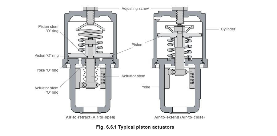
Atuadores pneumáticos são comumente usados para atuar válvulas de controle e estão disponíveis em duas formas principais; atuadores a pistão (Figura 6.6.1) e atuadores a diafragma (Figura 6.6.2)
Atuadores a pistão
Atuadores a pistão são geralmente usados onde o curso de um atuador a diafragma seria muito curto ou o empuxo muito pequeno. O ar comprimido é aplicado a um pistão sólido contido dentro de um cilindro sólido. Atuadores a pistão podem ser de ação simples ou dupla ação, podem suportar pressões de entrada mais altas e podem oferecer volumes de cilindro menores, que podem atuar em alta velocidade.
Atuadores a diafragma
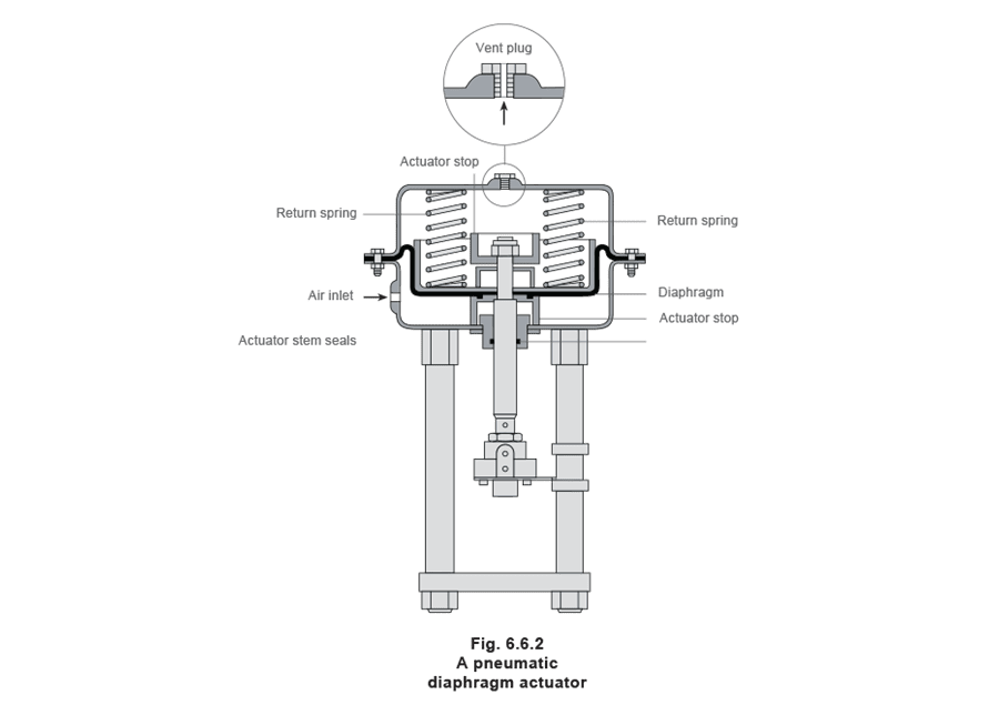
Atuadores a diafragma têm ar comprimido aplicado a uma membrana flexível chamada diafragma. A Figura 6.6.2 mostra um diafragma rolante onde a área efetiva do diafragma é praticamente constante durante todo o curso do atuador. Estes tipos de atuadores são de ação simples, pois o ar é fornecido apenas para um lado do diafragma, e podem ser de ação direta (mola para retrair) ou ação reversa (mola para estender).
 Reverse acting (spring-to-extend)
The operating force is derived from compressed air pressure, which is applied to a flexible diaphragm. The actuator is designed so that the force resulting from the air pressure, multiplied by the area of the diaphragm, overcomes the force exerted (in the opposite direction) by the spring(s).
Reverse acting (spring-to-extend)
The operating force is derived from compressed air pressure, which is applied to a flexible diaphragm. The actuator is designed so that the force resulting from the air pressure, multiplied by the area of the diaphragm, overcomes the force exerted (in the opposite direction) by the spring(s).
The diaphragm (Figure 6.6.2) is pushed upwards, pulling the spindle up, and if the spindle is connected to a direct acting valve, the plug is opened. The actuator is designed so that with a specific change of air pressure, the spindle will move sufficiently to move the valve through its complete stroke from fully-closed to fully-open.
As the air pressure decreases, the spring(s) moves the spindle in the opposite direction. The range of air pressure is equal to the stated actuator spring rating, for example 0.2 - 1 bar.
With a larger valve and/or a higher differential pressure to work against, more force is needed to obtain full valve movement.
To create more force, a larger diaphragm area or higher spring range is needed. This is why controls manufacturers offer a range of pneumatic actuators to match a range of valves – comprising increasing diaphragm areas, and a choice of spring ranges to create different forces.
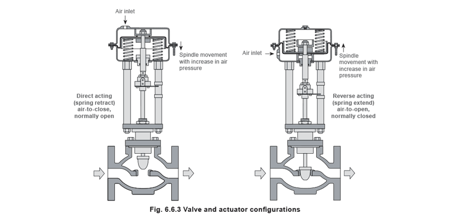
The diagrams in Figure 6.6.3 show the components of a basic pneumatic actuator and the direction of spindle movement with increasing air pressure.
 Direct acting actuator (spring-to-retract)
The direct acting actuator is designed with the spring below the diaphragm, having air supplied to the space above the diaphragm. The result, with increasing air pressure, is spindle movement in the opposite direction to the reverse acting actuator.
Direct acting actuator (spring-to-retract)
The direct acting actuator is designed with the spring below the diaphragm, having air supplied to the space above the diaphragm. The result, with increasing air pressure, is spindle movement in the opposite direction to the reverse acting actuator.
The effect of this movement on the valve opening depends on the design and type of valve used, and is illustrated in Figure 6.6.3.
There is however, an alternative, which is shown in Figure 6.6.4. A direct acting pneumatic actuator is coupled to a control valve with a reverse acting plug (sometimes called a ‘hanging plug’).
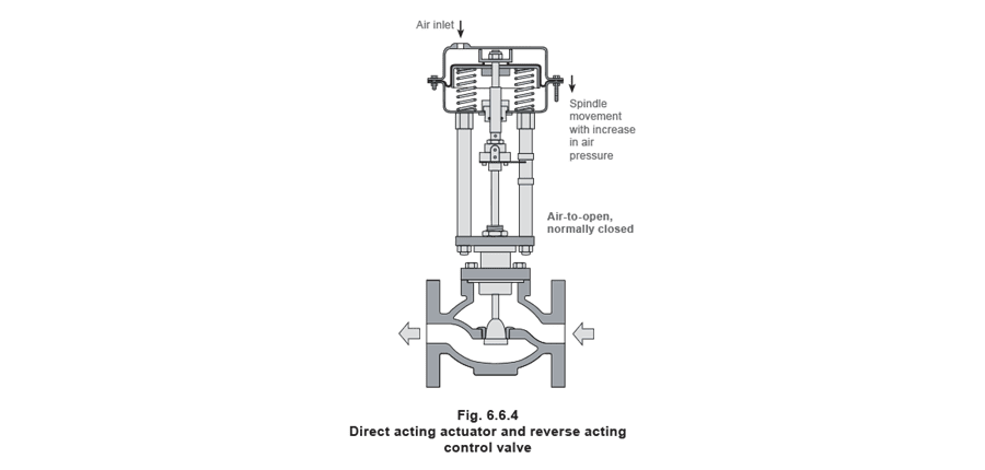 The choice between direct acting and reverse acting pneumatic controls depends on what position the valve should revert to in the event of failure of the compressed air supply. Should the valve close or be wide-open? This choice depends upon the nature of the application and safety requirements. It makes sense for steam valves to close on air failure, and cooling valves to open on air failure. The combination of actuator and valve type must be considered.
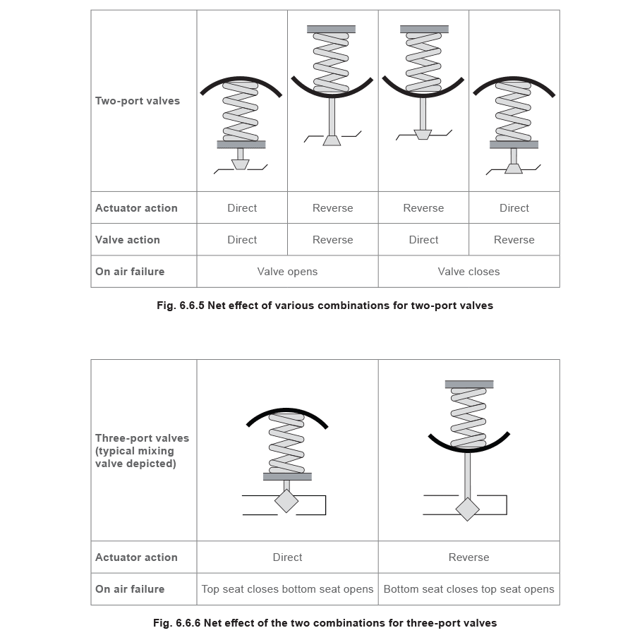
Figure 6.6.5 and Figure 6.6.6 show the net effect of the various combinations.
The choice between direct acting and reverse acting pneumatic controls depends on what position the valve should revert to in the event of failure of the compressed air supply. Should the valve close or be wide-open? This choice depends upon the nature of the application and safety requirements. It makes sense for steam valves to close on air failure, and cooling valves to open on air failure. The combination of actuator and valve type must be considered.
Figure 6.6.5 and Figure 6.6.6 show the net effect of the various combinations.
 Effect of differential pressure on the valve lift
The air fed into the diaphragm chamber is the control signal from the pneumatic controller. The most widely used signal air pressure is 0.2 bar to 1 bar. Consider a reverse acting actuator (spring-to-extend) with standard 0.2 to 1.0 bar spring(s), fitted to a direct acting valve (Figure 6.6.7).
Effect of differential pressure on the valve lift
The air fed into the diaphragm chamber is the control signal from the pneumatic controller. The most widely used signal air pressure is 0.2 bar to 1 bar. Consider a reverse acting actuator (spring-to-extend) with standard 0.2 to 1.0 bar spring(s), fitted to a direct acting valve (Figure 6.6.7).
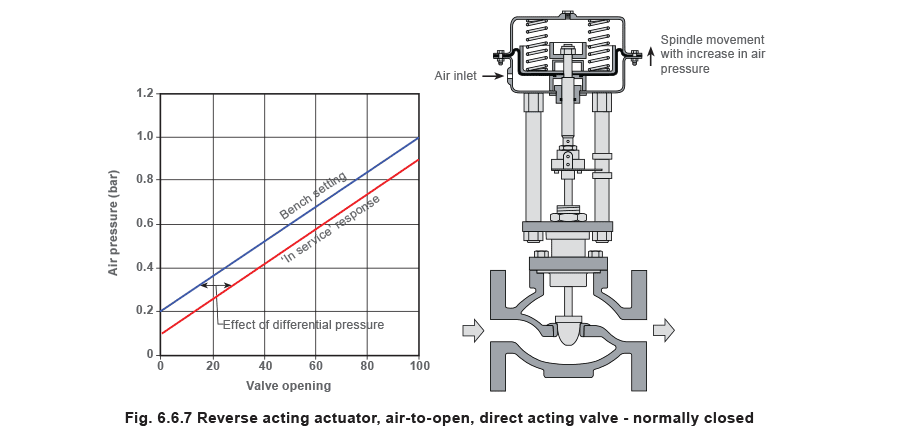 When the valve and actuator assembly is calibrated (or ‘bench set’), it is adjusted so that an air pressure of 0.2 bar will just begin to overcome the resistance of the springs and move the valve plug away from its seat.
As the air pressure is increased, the valve plug moves progressively further away from its seat, until finally at 1 bar air pressure, the valve is 100% open. This is shown graphically in Figure 6.6.7.
Now consider this assembly installed in a pipeline in a pressure reducing application, with 10 bar g on the upstream side and controlling the downstream pressure to 4 bar g.
The differential pressure across the valve is 10 - 4 = 6 bar. This pressure is acting on the underside of the valve plug, providing a force tending to open the valve. This force is in addition to the force provided by the air pressure in the actuator.
Therefore, if the actuator is supplied with air at 0.6 bar (halfway between 0.2 and 1 bar), for example, instead of the valve taking up the expected 50% open position, the actual opening will be greater, because of the extra force provided by the differential pressure.
Also, this additional force means that the valve is not closed at 0.2 bar. In order to close the valve in this example, the control signal must be reduced to approximately 0.1 bar.
The situation is slightly different with a steam valve controlling temperature in a heat exchanger, as the differential pressure across the valve will vary between:
- A minimum, when the process is calling for maximum heat, and the control valve is 100% open.
- A maximum, when the process is up to temperature and the control valve is closed. The steam pressure in the heat exchanger increases as the heat load increases. This can be seen in Module 6.5, Example 6.5.3 and Table 6.5.7.
If the pressure upstream of the control valve remains constant, then, as the steam pressure rises in the heat exchanger, the differential pressure across the valve must decrease.
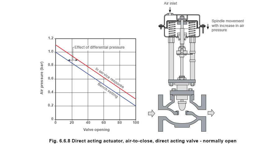
Figure 6.6.8 shows the situation with the air applied to a direct acting actuator. In this case, the force on the valve plug created by the differential pressure works against the air pressure. The effect is that if the actuator is supplied with air at 0.6 bar, for example, instead of the valve taking up the expected 50% open position, the percentage opening will be greater because of the extra force provided by the differential pressure. In this case, the control signal has to be increased to approximately 1.1. bar to fully close the valve.
 It may be possible to recalibrate the valve and actuator to take the forces created by differential pressure into account, or perhaps using different springs, air pressure and actuator combinations. This approach can provide an economic solution on small valves, with low differential pressures and where precise control is not required. However, the practicalities are that:
- Larger valves have greater areas for the differential pressure to act over, thus increasing the forces generated, and having an increasing effect on valve position.
- Higher differential pressures mean that higher forces are generated.
- Valves and actuators create friction, causing hysteresis. Smaller valves are likely to have greater friction relative to the total forces involved. The solution is to fit a positioner to the valve/actuator assembly. (More information is given on positioners later in this Module).
Note: For simplicity, the above examples assume a positioner is not used, and hysteresis is zero.
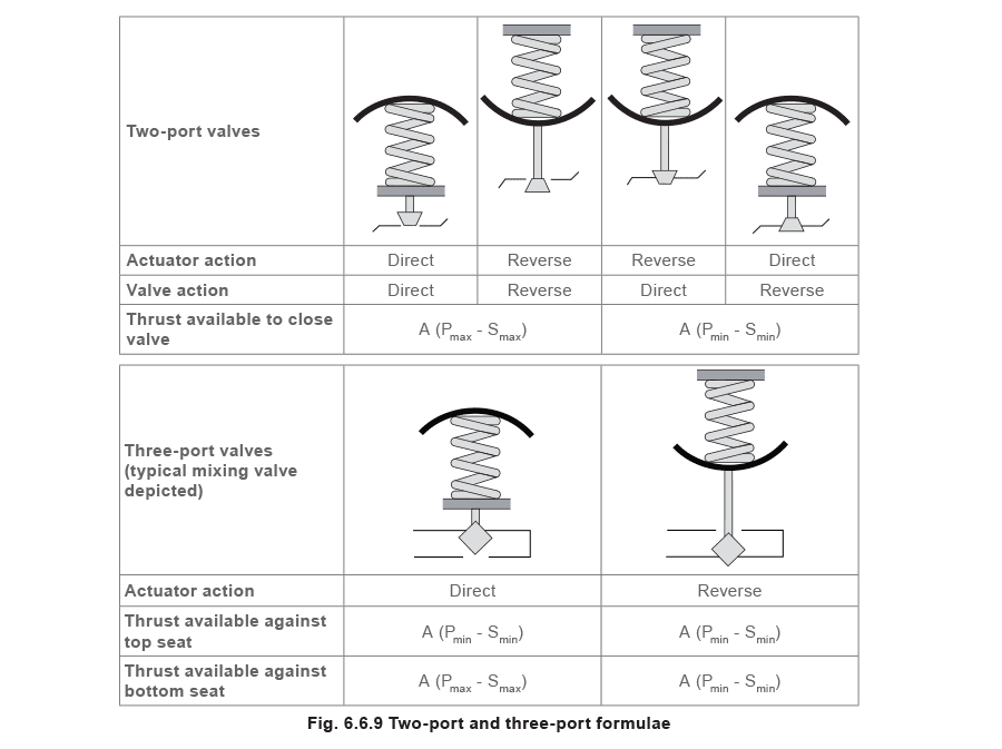
The formulae used to determine the thrust available to hold a valve on its seat for various valve and actuator combinations are shown in Figure 6.6.9.
Where:
A = Effective area of diaphragm
Pmax = Maximum pressure to actuator (normally 1.2 bar)
Smax = Maximum bench setting of spring
Pmin = Minimum pressure to actuator (normally 0 bar)
Smin = Minimum bench setting of spring
The thrust available to close the valve has to provide three functions:
- To overcome the fluid differential pressure at the closed position.
- To overcome friction in the valve and actuator, primarily at the valve and actuator stem seals.
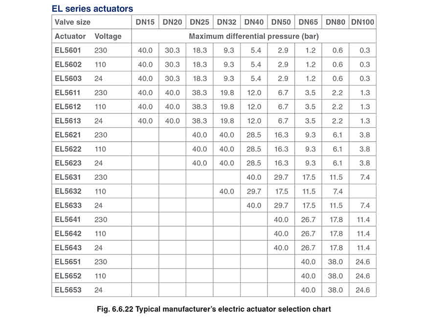
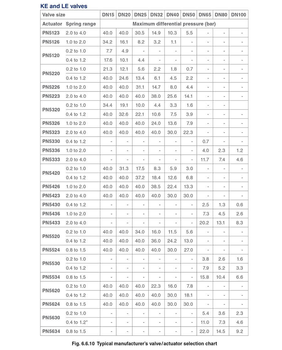
- To provide a sealing load between the valve plug and valve seat to ensure the required degree of tightness. Control valve manufacturers will normally provide full details of the maximum differential pressures against which their various valve and actuator/spring combinations will operate; the Table in Figure 6.6.10 is an example of this data.
Note: When using a positioner, it is necessary to refer to the manufacturer’s literature for the minimum and maximum air pressures.
Positioners Para muitas aplicações, a pressão de 0,2 a 1 bar na câmara do diafragma pode não ser suficiente para lidar com fricção e altas pressões diferenciais. Uma pressão de controle mais alta e molas mais fortes poderiam ser usadas, mas a solução prática é usar um positioner.
Este é um item adicional (veja Figura 6.6.11), que é geralmente montado no suporte ou pilares do atuador, e está ligado ao eixo do atuador por um braço de feedback para monitorar a posição da válvula. Requer sua própria fonte de ar de pressão mais alta, que usa para posicionar a válvula.
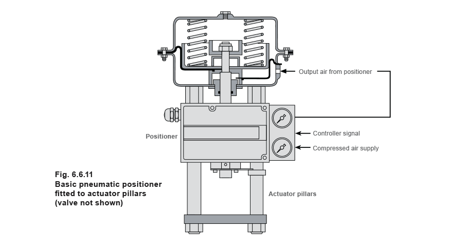 A valve positioner relates the input signal and the valve position, and will provide any output pressure to the actuator to satisfy this relationship, according to the requirements of the valve, and within the limitations of the maximum supply pressure.
When a positioner is fitted to an ‘air-to-open’ valve and actuator arrangement, the spring range may be increased to increase the closing force, and hence increase the maximum differential pressure a particular valve can tolerate. The air pressure will also be adjusted as required to overcome friction, therby reducing hysteresis effects.
Example: Taking a PN5400 series actuator fitted to a DN50 valve (see Table in Figure 6.6.10)
A valve positioner relates the input signal and the valve position, and will provide any output pressure to the actuator to satisfy this relationship, according to the requirements of the valve, and within the limitations of the maximum supply pressure.
When a positioner is fitted to an ‘air-to-open’ valve and actuator arrangement, the spring range may be increased to increase the closing force, and hence increase the maximum differential pressure a particular valve can tolerate. The air pressure will also be adjusted as required to overcome friction, therby reducing hysteresis effects.
Example: Taking a PN5400 series actuator fitted to a DN50 valve (see Table in Figure 6.6.10)
Atuadores elétricos ****Onde uma fonte pneumática não está disponível ou não é desejável, é possível usar um atuador elétrico para controlar a válvula. Atuadores elétricos usam um motor elétrico com requisitos de tensão na seguinte faixa: 230 Vac, 110 Vac, 24 Vac e 24 Vdc. Existem dois tipos de atuador elétrico; VMD (Acionamento Motor da Válvula) e Modulante.
VMD (Valve Motor Drive) This basic version of the electric actuator has three states:
- Driving the valve open.
- Driving the valve closed.
- No movement.
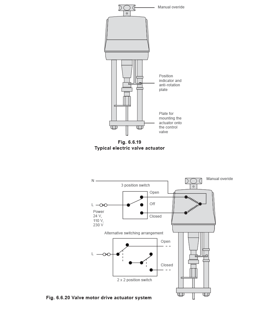 Figure 6.6.20 shows the VMD system where the forward and reverse travel of the actuator is controlled directly from any external 3-position or two 2-position switch units. The switches are rated at the actuator voltage and may be replaced by suitable relays.
Limiting devices are fitted within the VMD actuators to protect the motors from over-travel damage. These devices are based on either the maximum motor torque or physical position limit switches. Both devices stop the motor driving by interrupting the motor power supply.
- Position limit switches have the advantage that they can be adjusted to limit valve strokes in oversized valves.
- Torque switches have the advantage of giving a defined closing force on the valve seat, protecting the actuator in the case of valve stem seizure.
- If only position limit switches are used, they may be combined with a spring-loaded coupling to ensure tight valve shut-off. A VMD actuator may be used for on/off actuation or for modulating control. The controller positions the valve by driving the valve open or closed for a certain time, to ensure that it reaches the desired position. Valve position feedback may be used with some controllers Modulating In order to position the control valve in response to the system requirements a modulating actuator can be used. These units may have higher rated motors (typically 1 200 starts/hour) and may have built-in electronics.
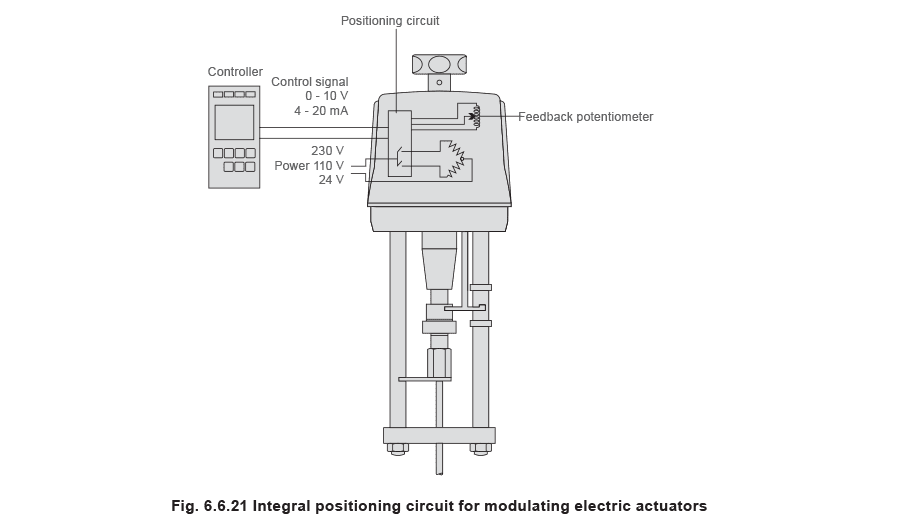
A positioning circuit may be included in the modulating actuator, which accepts an analogue control signal (typically 0-10 V or 4-20 mA). The actuator then interprets this control signal, as the valve position between the limit switches.
To achieve this, the actuator has a position sensor (usually a potentiometer), which feeds the actual valve position back to the positioning circuit. In this way the actuator can be positioned along its stroke in proportion to the control signal. A schematic of the modulating actuator is shown in Figure 6.6.21..
 Pneumatic actuators have an inherent fail-safe feature; should the air supply or control signal fail the valve will close. To provide this function in electric actuators, ‘spring reserve’ versions are available which will open or close the valve on power or control signal failure. Alternatively, fail-safe can be provided with battery power.
Electric actuators offer specified forces, which may be limited on spring reserve versions. The manufacturer’s charts should always be consulted during selection.
When sizing an actuator, it is wise to refer to the manufacturer’s technical data sheets for maximum differential pressure across the valve (see Figure 6.6.22).
Another limitation of an electric actuator is the speed of valve movement, which can be as low as 4 seconds/mm, which in rapidly varying systems may be too slow.