

Características de Válvulas de Controle
Vários tipos de características de fluxo estão disponíveis. Este tutorial discute os três principais tipos usados em aplicações de fluxo de água e vapor: abertura rápida, linear e porcentual igual de fluxo; como se comparam, e como (e por que) devem corresponder à aplicação em que são usados.
Características de fluxo Todas as válvulas de controle têm uma característica de fluxo inerente que define a relação entre ‘abertura da válvula’ e vazão sob condições de pressão constante. Observe que ‘abertura da válvula’ neste contexto refere-se à posição relativa do plugue da válvula em relação à sua posição fechada contra a sede da válvula. Não se refere à área de passagem do orifício. A área de passagem do orifício é às vezes chamada de ‘garganta da válvula’ e é o ponto mais estreito entre o plugue e a sede da válvula através do qual o fluido passa a qualquer momento. Para qualquer válvula, qualquer que seja sua caracterização, a relação entre a vazão e a área de passagem do orifício é sempre diretamente proporcional.
Válvulas de qualquer tamanho ou característica de fluxo inerente que estão sujeitas à mesma vazão volumétrica e pressão diferencial terão exatamente a mesma área de passagem do orifício. No entanto, diferentes características de válvula darão diferentes ‘aberturas de válvula’ para a mesma área de passagem. Comparando válvulas lineares e de porcentual igual, uma válvula linear pode ter uma abertura de válvula de 25% para uma certa queda de pressão e vazão, enquanto uma válvula de porcentual igual pode ter uma abertura de válvula de 65% para exatamente as mesmas condições. As áreas de passagem do orifício serão as mesmas.
A forma física do arranjo de plugue e sede, às vezes referido como ‘interno’ da válvula, causa a diferença na abertura da válvula entre essas válvulas. As formas típicas de internos para válvulas globo operadas por eixo são comparadas na Figura 6.5.1.
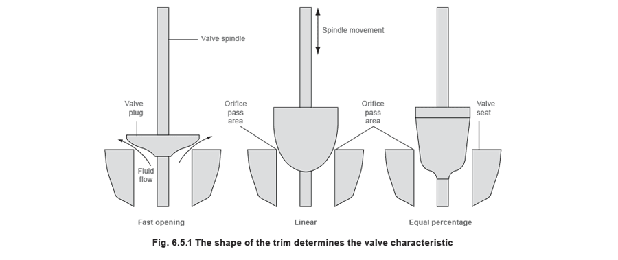 Neste Módulo, o termo ‘levantamento da válvula’ é usado para definir a abertura da válvula, seja a válvula uma válvula globo (movimento para cima e para baixo do plugue em relação à sede) ou uma válvula rotativa (movimento lateral do plugue em relação à sede).
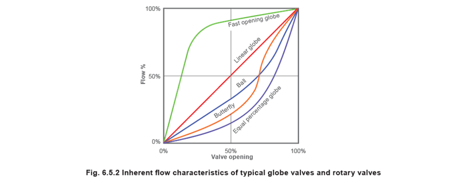
As válvulas rotativas (por exemplo, bola e borboleta) cada uma têm uma curva de característica básica, mas alterar os detalhes do plugue de bola ou borboleta pode modificar isso. As características de fluxo inerentes de válvulas globo típicas e válvulas rotativas são comparadas na Figura 6.5.2.
Examples of these and their inherent characteristics are shown in Figures 6.5.1 and 6.5.2.
 Característica de abertura rápida
O plugue da válvula com característica de abertura rápida dará uma grande mudança na vazão para um pequeno levantamento da válvula a partir da posição fechada. Por exemplo, um levantamento de 50% da válvula pode resultar em uma área de passagem do orifício e vazão de até 90% de seu potencial máximo.
Característica de abertura rápida
O plugue da válvula com característica de abertura rápida dará uma grande mudança na vazão para um pequeno levantamento da válvula a partir da posição fechada. Por exemplo, um levantamento de 50% da válvula pode resultar em uma área de passagem do orifício e vazão de até 90% de seu potencial máximo.
Uma válvula usando este tipo de plugue é às vezes referida como tendo uma característica ‘liga/desliga’.
Ao contrário das características lineares e de porcentual igual, a forma exata da curva de abertura rápida não é definida em normas. Portanto, duas válvulas, uma dando 80% de fluxo para 50% de levantamento, a outra 90% de fluxo para 60% de levantamento, podem ser consideradas como tendo uma característica de abertura rápida.
Válvulas de abertura rápida tendem a ser atuadas elétrica ou pneumaticamente e usadas para controle ‘liga/desliga’.
O tipo auto-acionado de válvula de controle tende a ter uma forma de plugue semelhante ao plugue de abertura rápida na Figura 6.5.1. A posição do plugue responde a mudanças na pressão de líquido ou vapor no sistema de controle. O movimento deste tipo de plugue de válvula pode ser extremamente pequeno em relação a pequenas mudanças na condição controlada, e consequentemente a válvula tem uma faixa inerentemente alta. O plugue da válvula é portanto capaz de reproduzir pequenas mudanças na vazão, e não deve ser considerado como uma válvula de controle de abertura rápida.
Característica linear
O plugue da válvula com característica linear é moldado de modo que a vazão é diretamente proporcional ao levantamento da válvula (H), a uma pressão diferencial constante. Uma válvula linear achieves isso tendo uma relação linear entre o levantamento da válvula e a área de passagem do orifício (veja Figura 6.5.3).
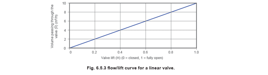 For example, at 40% valve lift, a 40% orifice size allows 40% of the full flow to pass.
Característica de porcentual igual (ou característica logarítmica)
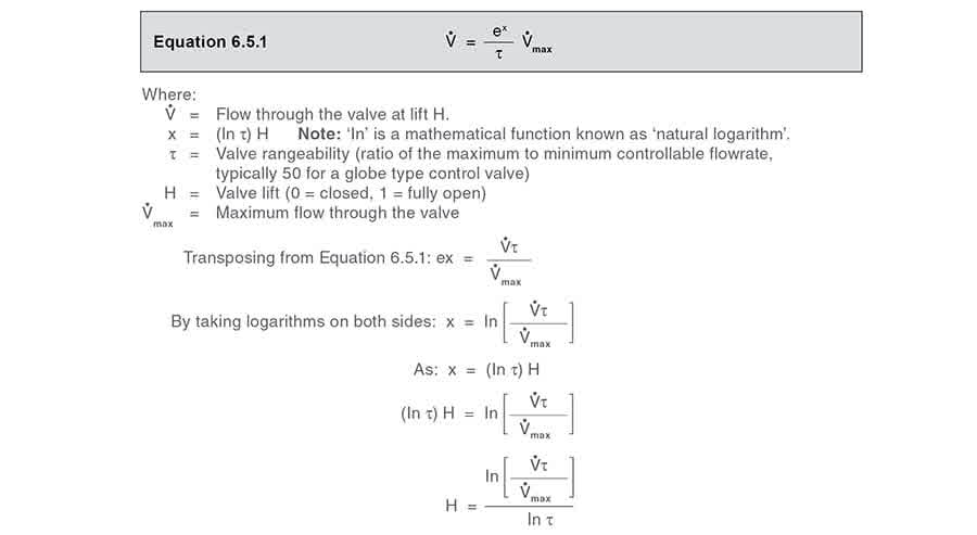
Estas válvulas têm um plugue moldado de modo que cada incremento no levantamento da válvula aumenta a vazão em uma certa porcentagem da vazão anterior. A relação entre o levantamento da válvula e o tamanho do orifício (e portanto a vazão) não é linear, mas logarítmica, e é expressa matematicamente na Equação 6.5.1:
 Exemplo 6.5.1
A vazão máxima através de uma válvula de controle com uma característica de porcentual igual é 10 m³/h. Se a válvula tem um turndown de 50:1, e está sujeita a uma pressão diferencial constante, usando a Equação 6.5.1 qual quantidade passará através da válvula com levantamentos de 40%, 50% e 60% respectivamente?
Exemplo 6.5.1
A vazão máxima através de uma válvula de controle com uma característica de porcentual igual é 10 m³/h. Se a válvula tem um turndown de 50:1, e está sujeita a uma pressão diferencial constante, usando a Equação 6.5.1 qual quantidade passará através da válvula com levantamentos de 40%, 50% e 60% respectivamente?
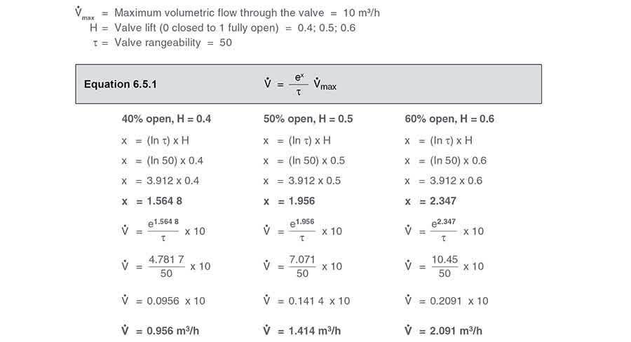 O aumento na vazão volumétrica através deste tipo de válvula de controle aumenta em uma porcentual igual por incremento igual de movimento da válvula:
- Quando a válvula está 50% aberta, ela passará 1,414 m³/h, um aumento de 48% sobre o fluxo de 0,956 m³/h quando a válvula está 40% aberta.
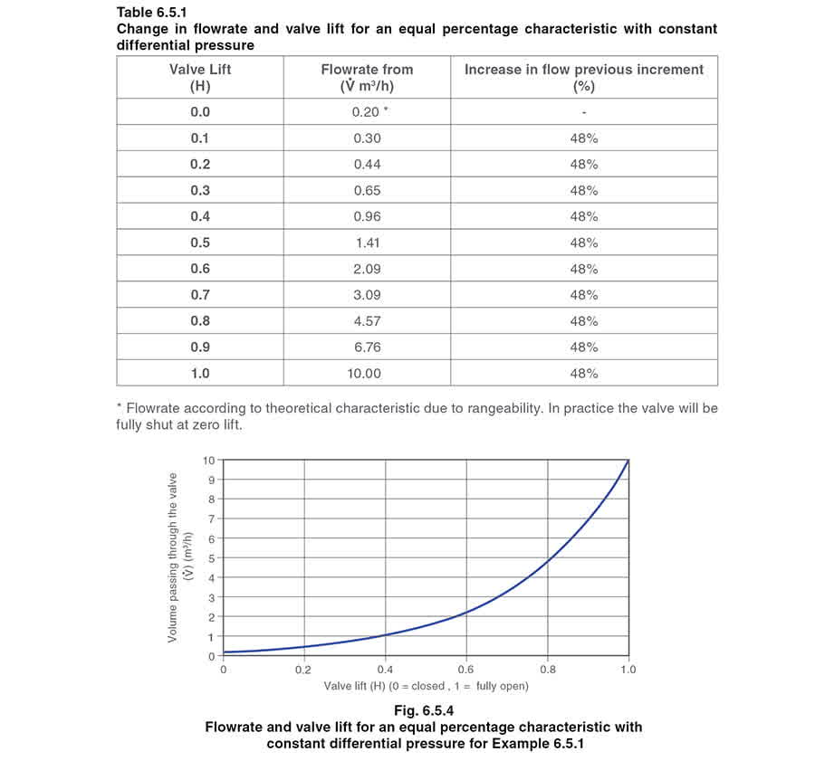
- Quando a válvula está 60% aberta, ela passará 2,091 m³/h, um aumento de 48% sobre o fluxo de 1,414 m³/h quando a válvula está 50% aberta. Pode-se ver que (com uma pressão diferencial constante) para qualquer aumento de 10% no levantamento da válvula, há um aumento de 48% na vazão através da válvula de controle. Este será sempre o caso para uma válvula de porcentual igual com faixa de 50. Para referência, se uma válvula tem uma faixa de 100, o aumento incremental na vazão para uma mudança de 10% no levantamento da válvula é 58%.
A Tabela 6.5.1 mostra como a mudança na vazão se altera ao longo da faixa de levantamento da válvula para a válvula de porcentual igual no Exemplo 6.5.1 com uma faixa de 50 e com uma pressão diferencial constante.
 Algumas outras características inerentes de válvulas são às vezes usadas, como parabólica, linear modificada ou hiperbólica, mas os tipos mais comuns em fabricação são abertura rápida, linear e porcentual igual.
Correspondendo a característica da válvula à característica da instalação
Cada aplicação terá uma característica de instalação única que relaciona o fluxo do fluido à demanda de calor. A pressão diferencial através da válvula controlando o fluxo do fluido de aquecimento também pode variar:
Algumas outras características inerentes de válvulas são às vezes usadas, como parabólica, linear modificada ou hiperbólica, mas os tipos mais comuns em fabricação são abertura rápida, linear e porcentual igual.
Correspondendo a característica da válvula à característica da instalação
Cada aplicação terá uma característica de instalação única que relaciona o fluxo do fluido à demanda de calor. A pressão diferencial através da válvula controlando o fluxo do fluido de aquecimento também pode variar:
- Em sistemas hídricos, a curva de característica da bomba significa que à medida que o fluxo é reduzido, a pressão da válvula a montante é aumentada (consulte o Exemplo 6.5.2, e o Módulo 6.3).
- Em sistemas de controle de temperatura por vapor, a queda de pressão sobre a válvula de controle é deliberadamente variada para satisfazer a carga térmica necessária. A característica da válvula de controle escolhida para uma aplicação deve resultar em uma relação direta entre abertura da válvula e fluxo, ao longo de tanto quanto possível do curso da válvula.
Esta seção considerará as várias opções de características de válvula para controlar sistemas hídricos e de vapor. Em geral, válvulas lineares são usadas para sistemas hídricos enquanto sistemas de vapor tendem a operar melhor com válvulas de porcentual igual.
1. Um sistema de aquecimento por circulação de água com válvula de três vias
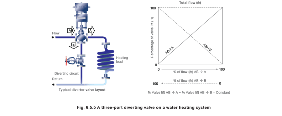 Em sistemas hídricos onde uma vazão constante de água é misturada ou desviada por uma válvula de três vias em um circuito balanceado, a perda de pressão sobre a válvula é mantida o mais estável possível para manter o equilíbrio no sistema**.
Conclusão** - A melhor escolha nestas aplicações é geralmente uma válvula com característica linear. Por causa disso, as características instaladas e inerentes são sempre semelhantes e lineares, e haverá ganho limitado no laço de controle.2. Um sistema de controle de nível de água de caldeira – um sistema hídrico com válvula de duas vias Em sistemas deste tipo (um exemplo é mostrado na Figura 6.5.6), onde uma válvula de controle de água de alimentação de duas vias varia a vazão de água, a queda de pressão através da válvula de controle variará com o fluxo. Esta variação é causada por:
- A característica da bomba. À medida que a vazão é reduzida, a pressão diferencial entre a bomba e a caldeira é aumentada (este fenômeno é discutido em mais detalhes no Módulo 6.3).
- A resistência à fricção da tubulação muda com a vazão. A carga perdida por fricção é proporcional ao quadrado da velocidade. (Este fenômeno é discutido em mais detalhes no Módulo 6.3).
- The pressure within the boiler will vary as a function of the steam load, the type of burner control system and its mode of control.
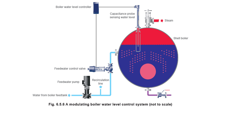 Example 6.5.2 Select and size the feedwater valve in Figure 6.5.6
In a simplified example (which assumes a constant boiler pressure and constant friction loss in the pipework), a boiler is rated to produce 10 tonnes of steam per hour. The boiler feedpump performance characteristic is tabulated in Table 6.5.2, along with the resulting differential pressure (ΔP) across the feedwater valve at various flowrates at, and below, the maximum flow requirement of 10 m³/h of feedwater.
Example 6.5.2 Select and size the feedwater valve in Figure 6.5.6
In a simplified example (which assumes a constant boiler pressure and constant friction loss in the pipework), a boiler is rated to produce 10 tonnes of steam per hour. The boiler feedpump performance characteristic is tabulated in Table 6.5.2, along with the resulting differential pressure (ΔP) across the feedwater valve at various flowrates at, and below, the maximum flow requirement of 10 m³/h of feedwater.
Note: The valve ΔP is the difference between the pump discharge pressure and a constant boiler pressure of 10 bar g. Note that the pump discharge pressure will fall as the feedwater flow increases. This means that the water pressure before the feedwater valve also falls with increased flowrate, which will affect the relationship between the pressure drop and the flowrate through the valve.
It can be determined from Table 6.5.2 that the fall in the pump discharge pressure is about 26% from no-load to full-load, but the fall in differential pressure across the feedwater valve is a lot greater at 72%. If the falling differential pressure across the valve is not taken into consideration when sizing the valve, the valve could be undersized.
 As discussed in Modules 6.2 and 6.3, valve capacities are generally measured in terms of Kv. More specifically, Kvs relates to the pass area of the valve when fully open, whilst Kvr relates to the pass area of the valve as required by the application.
Consider if the pass area of a fully open valve with a Kvs of 10 is 100%. If the valve closes so the pass area is 60% of the full-open pass area, the Kvr is also 60% of 10 = 6. This applies regardless of the inherent valve characteristic. The flowrate through the valve at each opening will depend upon the differential pressure at the time.
Using the data in Table 6.5.2, the required valve capacity, Kvr, can be calculated for each incremental flowrate and valve differential pressure, by using Equation 6.5.2, which is derived from Equation 6.3.2.The Kvr can be thought of as being the actual valve capacity required by the installation and, if plotted against the required flowrate, the resulting graph can be referred to as the ‘installation curve’.
As discussed in Modules 6.2 and 6.3, valve capacities are generally measured in terms of Kv. More specifically, Kvs relates to the pass area of the valve when fully open, whilst Kvr relates to the pass area of the valve as required by the application.
Consider if the pass area of a fully open valve with a Kvs of 10 is 100%. If the valve closes so the pass area is 60% of the full-open pass area, the Kvr is also 60% of 10 = 6. This applies regardless of the inherent valve characteristic. The flowrate through the valve at each opening will depend upon the differential pressure at the time.
Using the data in Table 6.5.2, the required valve capacity, Kvr, can be calculated for each incremental flowrate and valve differential pressure, by using Equation 6.5.2, which is derived from Equation 6.3.2.The Kvr can be thought of as being the actual valve capacity required by the installation and, if plotted against the required flowrate, the resulting graph can be referred to as the ‘installation curve’.
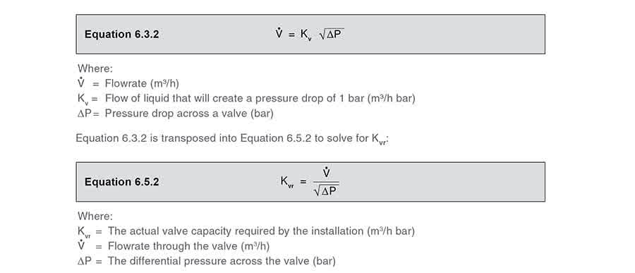 At the full-load condition, from Table 6.5.2:
Required flow through the valve = 10 m³/ h
ΔP across the valve = 1.54 bar
From Equation 6.5.2:

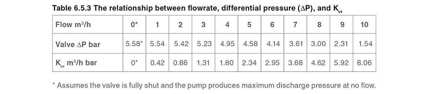
Taking the valve flowrate and valve ΔP from Table 6.5.2, a Kvr for each increment can be determined from Equation 6.5.2; and these are tabulated in Table 6.5.3.
 Constructing the installation curve
The Kvr of 8.06 satisfies the maximum flow condition of 10 m3/h for this example.
Constructing the installation curve
The Kvr of 8.06 satisfies the maximum flow condition of 10 m3/h for this example.
The installation curve could be constructed by comparing flowrate to Kvr, but it is usually more convenient to view the installation curve in percentage terms. This simply means the percentage of Kvr to Kvs, or in other words, the percentage of actual pass area relative to the full open pass area.
For this example: The installation curve is constructed, by taking the ratio of Kvr at any load relative to the Kvs of 8.06. A valve with a Kvs of 8.06 would be ‘perfectly sized’, and would describe the installation curve, as tabulated in Table 6.5.4, and drawn in Figure 6.5.7. This installation curve can be thought of as the valve capacity of a perfectly sized valve for this example.****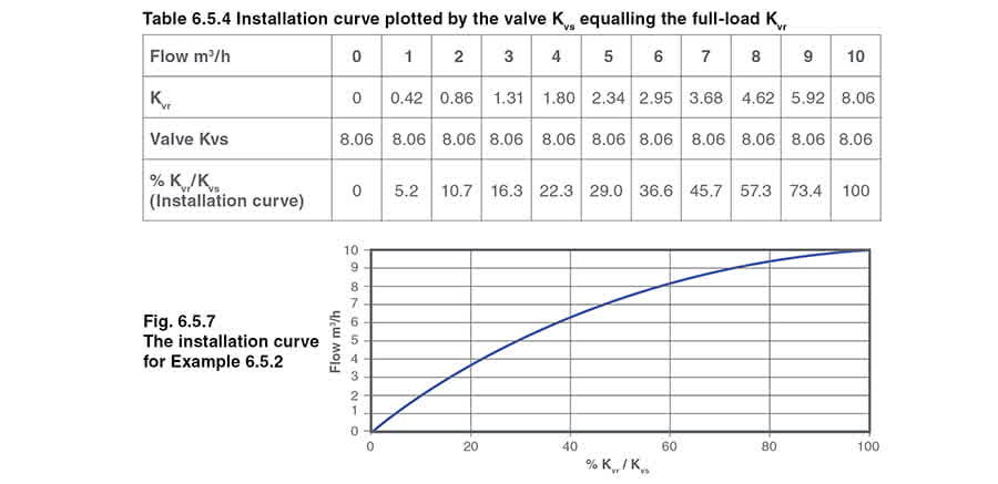 It can be seen that, as the valve is ‘perfectly sized’ for this installation, the maximum flowrate is satisfied when the valve is fully open.
However, it is unlikely and undesirable to select a perfectly sized valve. In practice, the selected valve would usually be at least one size larger, and therefore have a Kvs larger than the installation Kvr.
As a valve with a Kvs of 8.06 is not commercially available, the next larger standard valve would have a Kvs of 10 with nominal DN25 connections.
It is interesting to compare linear and equal percentage valves having a Kvs of 10 against the installation curve for this example.
Consider a valve with a linear inherent characteristic
A valve with a linear characteristic means that the relationship between valve lift and orifice pass area is linear. Therefore, both the pass area and valve lift at any flow condition is simply the Kvr expressed as a proportion of the valve Kvs. For example: ****
It can be seen from Table 6.5.4, that at the maximum flowrate of 10 m³/h, the Kvr is 8.06. If the linear valve has a Kvs of 10, for the valve to satisfy the required maximum flowrate, the valve will lift:
****
It can be seen from Table 6.5.4, that at the maximum flowrate of 10 m³/h, the Kvr is 8.06. If the linear valve has a Kvs of 10, for the valve to satisfy the required maximum flowrate, the valve will lift:
 Using the same routine, the orifice size and valve lift required at various flowrates may be determined for the linear valve, as shown in Table 6.5.5.
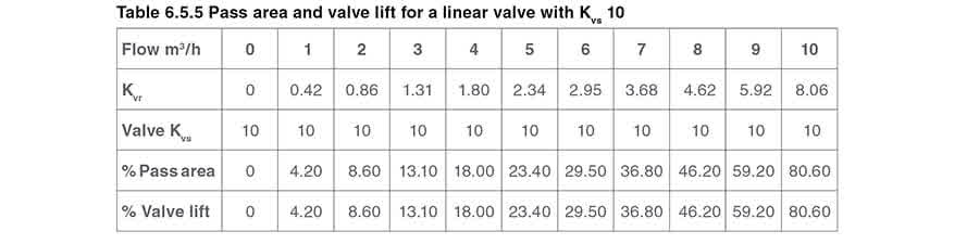 An equal percentage valve will require exactly the same pass area to satisfy the same maximum flowrate, but its lift will be different to that of the linear valve.
Consider a valve with an equal percentage inherent characteristic
Given a valve rangeability of 50:1, τ = 50, the lift (H) may be determined using Equation 6.5.1:
Percentage valve lift is denoted by Equation 6.5.3.
 As the volumetric flowrate through any valve is proportional to the orifice pass area, Equation 6.5.3 can be modified to give the equal percentage valve lift in terms of pass area and therefore Kv.
This is shown by Equation 6.5.4.
 As already calculated, the Kvr at the maximum flowrate of 10 m³/h is 8.06, and the Kvs of the DN25 valve is 10. By using Equation 6.5.4 the required valve lift at full-load is therefore:therefore:

Tabela 6.5.10 Comparando levantamentos de válvulas (Kvs 160) o Kvr e a curva de instalação
Tabela**** 6.5.10 Comparando levantamentos de válvulas (Kvs 160) o Kvr e a curva de instalação
| Secondary water flowrate (kg/s) | 0 | 1 | 2 | 3 | 4 | 5 | 6 | 7 | 8 | 9 | 10 |
| Kvr | 0 | 5.3 | 10.7 | 16.2 | 21.9 | 27.6 | 33.6 | 39.7 | 46 | 53.8 | 69 |
| Valve Kvs | 160 | 160 | 160 | 160 | 160 | 160 | 160 | 160 | 160 | 160 | 160 |
| % Lift - Linear valve | 0 | 3.3 | 6.7 | 10.1 | 13.7 | 17.3 | 21 | 24.8 | 28.8 | 33.6 | 43 |
| % Lift - Equal percentage valve | 0 | 13.1 | 30.9 | 41.5 | 49.1 | 55.1 | 60.1 | 64.4 | 68.2 | 72.1 | 78 |
| % Installation curve* | 0 | 7.7 | 15.5 | 23.5 | 31.6 | 40 | 48.6 | 57.4 | 66.5 | 77.8 | 100 |
*The installation curve is the percentage of Kvr at any load to the Kvr at maximum load
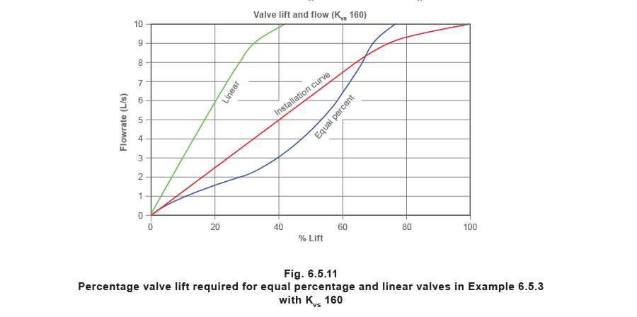
It can be seen from Figure 6.5.11 that both valve curves have moved to the left when compared to the smaller (properly sized) valves in Figure 6.5.10, whilst the installation curve remains static.
The change for the linear valve is quite dramatic; it can be seen that, at 30% load, the valve is only 10% open. Even at 85% load, the valve is only 30% open. It may also be observed that the change in flowrate is large for a relatively small change in the lift. This effectively means that the valve is operating as a fast acting valve for up to 90% of its range. This is not the best type of inherent characteristic for this type of steam installation, as it is usually better for changes in steam flow to occur fairly slowly.
Although the equal percentage valve curve has moved position, it is still to the right of the installation curve and able to provide good control. The lower part of its curve is relatively shallow, offering slower opening during its initial travel, and is better for controlling steam flow than the linear valve in this case.
Circumstances that can lead to over-sizing include:
- The application data is approximate, consequently an additional ‘safety factor’ is included.
- Sizing routines that include operational ‘factors’ such as an over-zealous allowance for fouling.
- The calculated Kvr is only slightly higher than the Kvs of a standard valve, and the next larger size has to be selected. There are also situations where:
- The available pressure drop over the control valve at full-load is low. For example, if the steam supply pressure is 4.5 bar a and the steam pressure required in the heat exchanger at full-load is 4 bar a, this only gives an 11% pressure drop at full-load.
- The minimum load is a lot less than the maximum load A linear valve characteristic would mean that the valve plug operates close to the seat, with the possibility of damage.
In these common circumstances, the equal percentage valve characteristic will provide a much more flexible and practical solution.
This is why most control valve manufacturers will recommend an equal percentage characteristic for two-port control valves, especially when used on compressible fluids such as steam.
Please note: Given the opportunity, it is better to size steam valves with as high a pressure drop as possible at maximum load; even with critical pressure drop occurring across the control valve if the conditions allow. This helps to reduce the size and cost of the control valve, gives a more linear installation curve, and offers an opportunity to select a linear valve.
However, conditions may not allow this. The valve can only be sized on the application conditions. For example, should the heat exchanger working pressure be 4.5 bar a, and the maximum available steam pressure is only 5 bar a, the valve can only be sized on a 10% pressure drop ([5 – 4.5]/5). In this situation, sizing the valve on critical pressure drop would have reduced the size of the control valve and starved the heat exchanger of steam.
If it were impossible to increase the steam supply pressure, a solution would be to install a heat exchanger that operates at a lower operating pressure. In this way, the pressure drop would increase across the control valve. This could result in a smaller valve but also a larger heat exchanger, because the heat exchanger operating temperature is now lower.
Another set of advantages accrues from larger heat exchangers operating at lower steam pressures:
- There is less propensity for scaling and fouling on the heating surfaces.
- There is less flash steam produced in the condensate system.
- There is less backpressure in the condensate system. A balance has to be made between the cost of the control valve and heat exchanger, the ability of the valve to control properly, and the effects on the rest of the system as seen above. On steam systems, equal percentage valves will usually be a better choice than linear valves, because if low pressure drops occur, they will have less of an affect on their performance over the complete range of valve movement.