Controles de Temperatura Auto-acionados
Este tutorial fornece uma introdução básica sobre o que são os sistemas de controle de temperatura auto-acionados e como funcionam. Os vários tipos diferentes de válvulas e controladores são brevemente discutidos juntamente com aplicações típicas para sistemas de vapor e água.
O que são controles de temperatura auto-acionados e como funcionam?
O que são controles de temperatura auto-acionados e como funcionam?
Existem duas formas principais de controle de temperatura auto-acionado disponíveis no mercado: Sistemas preenchidos com líquido e sistemas de tensão de vapor.
Os controles de temperatura auto-acionados são autoalimentados, sem necessidade de eletricidade ou ar comprimido.
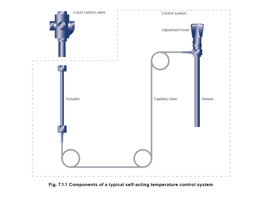
O sistema de controle é uma unidade de peça única compreendendo um sensor, tubulação capilar e um atuador.
Isto é então conectado à válvula de controle apropriada, conforme mostrado na Figura 7.1.1.
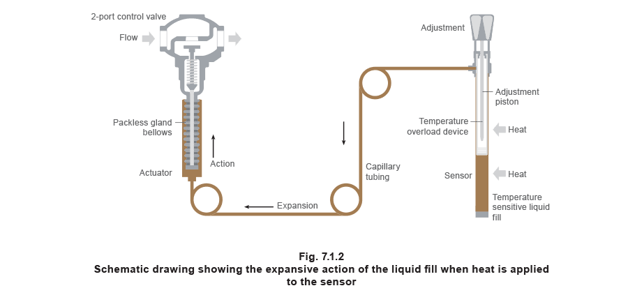
O princípio auto-acionado Se um fluido sensível à temperatura for aquecido, ele se expandirá. Se for resfriado, ele se contrairá. No caso de um controle de temperatura auto-acionado, o fluido sensível à temperatura no sensor e capilar se expandirá com o aumento da temperatura (veja Figura 7.1.2). A força criada por esta expansão (ou contração no caso de menos calor sendo aplicado ao sensor) é transferida através do capilar para o atuador, abrindo ou fechando assim a válvula de controle, e por sua vez controlando o fluxo de fluido através da válvula de controle. O fluido hidráulico permanece como um líquido.
Existe uma relação linear entre a mudança de temperatura no sensor e a quantidade de movimento no atuador. Assim, a mesma quantidade de movimento pode ser obtida para cada unidade igual de aumento ou queda de temperatura. Isso significa que um sistema de controle de temperatura auto-acionado fornece ‘controle proporcional’; toda a faixa da banda proporcional atuando acima ou abaixo do ponto de ajuste, dependendo se a aplicação é aquecimento ou resfriamento. Por exemplo, se a banda proporcional de um sistema de aquecimento auto-acionado fosse 5°C, e o ponto de ajuste fosse 70°C, então a válvula estaria totalmente fechada a 70°C e totalmente aberta a 65°C. Com um controle de resfriamento ajustado em 70°C, a válvula estaria totalmente aberta a 70°C e totalmente fechada a 65°C. A banda proporcional varia de acordo com o tamanho da válvula, válvulas maiores tendo bandas P maiores. Se uma válvula for muito grande para a aplicação, o único problema real é que a estabilidade do sistema será comprometida; se o orifício da válvula for maior do que deveria, uma pequena mudança na condição controlada (talvez a temperatura do fluxo secundário de um calorificador de aquecimento) permite uma mudança muito grande no fluxo de vapor. O resultado é que o sistema pode operar de maneira liga-desliga, em vez de uma maneira modulante. Para baixar a temperatura de ajuste
O botão de ajuste é girado no sentido horário para inserir o pistão mais profundamente no sensor. Isso efetivamente reduz a quantidade de espaço para o preenchimento líquido, o que significa que a válvula está fechada em uma temperatura mais baixa. A temperatura de ajuste será portanto mais baixa. Em sistemas de controle com ajustes do tipo mostrador, o mesmo efeito será achieved (tipicamente) usando uma chave de fenda para girar o parafuso de ajuste no sentido horário. Para elevar a temperatura de ajuste
O botão de ajuste é girado no sentido anti-horário para diminuir o comprimento do pistão inserido no sensor. Isso aumenta a quantidade de espaço para o preenchimento líquido, o que significa que uma temperatura mais alta será necessária para causar a expansão suficiente do preenchimento para fechar a válvula de controle. A temperatura de ajuste será portanto mais alta. Novamente, tipicamente para um ajuste do tipo mostrador, uma chave de fenda é usada para girar o parafuso de ajuste no sentido anti-horário. Proteção contra altas temperaturas Em caso de ultrapassagem de temperatura acima da temperatura de ajuste (possíveis causas das quais podem ser uma válvula de controle com vazamento, ajuste incorreto, ou uma fonte de calor adicional separada); uma série de molas de disco alojadas dentro do pistão absorverá a expansão excessiva do preenchimento. Isso impedirá que o sistema de controle se rompa. Quando a ultrapassagem de temperatura cessar, as molas de disco retornarão à sua posição original e o sistema de controle funcionará normalmente. A ultrapassagem é tipicamente de 30°C a 50°C acima da temperatura de ajuste, de acordo com o tipo de controle.
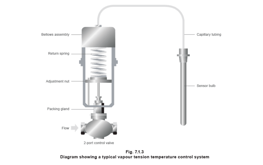
A vapour tension control system has a sensing system filled with a mixture of liquid and vapour. An increase in the sensor temperature boils off a greater proportion of the vapour from the liquid held within it, increasing the vapour pressure in the sensor and capillary system. This increase in pressure is transmitted through the capillary to a bellows or diaphragm assembly at the opposite end (see Figure 7.1.3).
 A vapour tension system follows a unique pressure / temperature saturation curve for the fluid contained by the system. All fluids have a relationship between pressure and their boiling temperature. The result can be plotted by a saturation curve. The saturation curve for water can be seen in Figure 7.1.4.
Figure 7.1.4 illustrates how a 5°C temperature change at 150°C will cause a 0.65 bar change in system pressure. At the bottom of the scale, a 5°C temperature change only results in a 0.18 bar change in system pressure. Thus for the same temperature change, the valve will move a greater amount at the top end of the temperature range than at the bottom end.
A vapour tension system follows a unique pressure / temperature saturation curve for the fluid contained by the system. All fluids have a relationship between pressure and their boiling temperature. The result can be plotted by a saturation curve. The saturation curve for water can be seen in Figure 7.1.4.
Figure 7.1.4 illustrates how a 5°C temperature change at 150°C will cause a 0.65 bar change in system pressure. At the bottom of the scale, a 5°C temperature change only results in a 0.18 bar change in system pressure. Thus for the same temperature change, the valve will move a greater amount at the top end of the temperature range than at the bottom end.
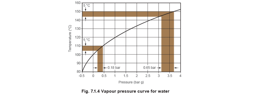 Therefore to move a valve from fully open to fully closed requires a greater temperature change at the bottom end of the range than at the top. Manufacturers of these types of vapour tension control systems often suggest that the control be used only at the top end of its range, but this means that to cover a reasonable temperature span, different fills are used (including water, methyl alcohol and benzene).
Alternatively, a liquid filled system will give a true linear relationship between temperature change and valve movement, largely due to liquid being incompressible. The set temperature can be calibrated in degrees and not simply by a series of numbers. There is no confusion over adjusting the set temperature; which reduces commissioning time. Also, adjustment, which is carried out by altering the amount of space available for the liquid fill, can be carried out anywhere between the control valve and the sensor. This is not so with vapour tension systems, which can usually only be adjusted at the control valve.
Therefore to move a valve from fully open to fully closed requires a greater temperature change at the bottom end of the range than at the top. Manufacturers of these types of vapour tension control systems often suggest that the control be used only at the top end of its range, but this means that to cover a reasonable temperature span, different fills are used (including water, methyl alcohol and benzene).
Alternatively, a liquid filled system will give a true linear relationship between temperature change and valve movement, largely due to liquid being incompressible. The set temperature can be calibrated in degrees and not simply by a series of numbers. There is no confusion over adjusting the set temperature; which reduces commissioning time. Also, adjustment, which is carried out by altering the amount of space available for the liquid fill, can be carried out anywhere between the control valve and the sensor. This is not so with vapour tension systems, which can usually only be adjusted at the control valve.
- Vapour tension control valves sometimes leak through the stem. To avoid the extra cost of having a second bellows sealing mechanism, most manufacturers of vapour tension controls use a mechanical seal on the valve stem. These tend to be either too loose, causing leaks; or too tight, causing too much spindle friction and the valve to stick.
- In liquid systems, because the valve movement is truly proportional to temperature change and the valve seal is frictionless, the temperature control has a very high rangeability and can control at very light loads.
As válvulas para uso com sistemas de controle de temperatura auto-acionados podem ser divididas em três grupos:
- Válvulas de duas vias normalmente abertas.
- Válvulas de duas vias normalmente fechadas.
- Válvulas de mistura ou desvio de três vias.
Válvulas de controle de duas vias normalmente abertas
Estas válvulas são para aplicações de aquecimento, que é o tipo mais comum de aplicação. São mantidas na posição aberta por uma mola. Uma vez que o sistema está em operação, qualquer aumento na temperatura, detectado pelo sensor, fará o preenchimento se expandir e começar a fechar a válvula, restringindo o fluxo do meio de aquecimento.
Válvulas de controle de duas vias normalmente fechadas
Estas válvulas são para aplicações de resfriamento. São mantidas na posição fechada por uma mola. Quando o sistema está em operação, qualquer aumento na temperatura fará o preenchimento se expandir e começar a abrir a válvula, permitindo que o meio de resfriamento flua.
Força necessária para fechar uma válvula de controle auto-acionada
A força de fechamento necessária no plugue da válvula é o produto da área do orifício da válvula e da pressão diferencial, conforme mostrado na Equação 7.1.1. Observe que para válvulas de vapor de duas vias, a pressão diferencial deve ser tomada como a pressão absoluta do vapor a montante; enquanto para válvulas de água de duas vias será a pressão manométrica máxima da bomba menos a perda de pressão ao longo da tubulação entre a bomba e a entrada da válvula.
 Exemplo 7.1.1
Calcule a força necessária para fechar a válvula se o orifício de uma válvula de vapor tem 20 mm de diâmetro e a pressão do vapor é 9 bar g. (A pressão diferencial máxima é 9 + 1 = 10 bar absoluto).
Exemplo 7.1.1
Calcule a força necessária para fechar a válvula se o orifício de uma válvula de vapor tem 20 mm de diâmetro e a pressão do vapor é 9 bar g. (A pressão diferencial máxima é 9 + 1 = 10 bar absoluto).
 Isso significa que o atuador deve fornecer pelo menos 314 newtons para fechar a válvula de controle contra a pressão do vapor a montante de 9 bar g.
Pode-se ver do Exemplo 7.1.1 que a força necessária para fechar a válvula aumenta com o quadrado do diâmetro. Há uma quantidade limitada de força disponível do atuador, é por isso que a pressão máxima contra a qual uma válvula é capaz de fechar diminui com o aumento do tamanho da válvula.
Isso efetivamente limitaria os controles de temperatura auto-acionados a baixas pressões em tamanhos acima de DN25, se não fosse por um recurso de balanceamento. O balanceamento pode ser achieved por meio de um fole ou um arranjo de sede dupla. Válvulas balanceadas por fole
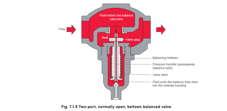
Em uma válvula balanceada por fole, um fole de balanceamento com a mesma área efetiva que o orifício da sede é usado para contrabalançar as forças atuando no plugue da válvula. Um pequeno furo no centro do caule da válvula forma um tubo de balanceamento, permitindo que a pressão a montante do plugue da válvula seja alimentada para o alojamento do fole (veja Figura 7.1.5). Da mesma forma, as forças no plugue da válvula pressurizam o interior do fole. A pressão diferencial através do fole é portanto a mesma que a pressão diferencial através do plugue da válvula, mas como as forças atuam em direções opostas, elas se cancelam mutuamente.
O fole de balanceamento pode ser tipicamente fabricado de:
- Bronze fosforoso.
- Aço inoxidável, que permite pressões e temperaturas mais altas.
 Double-seated control valves
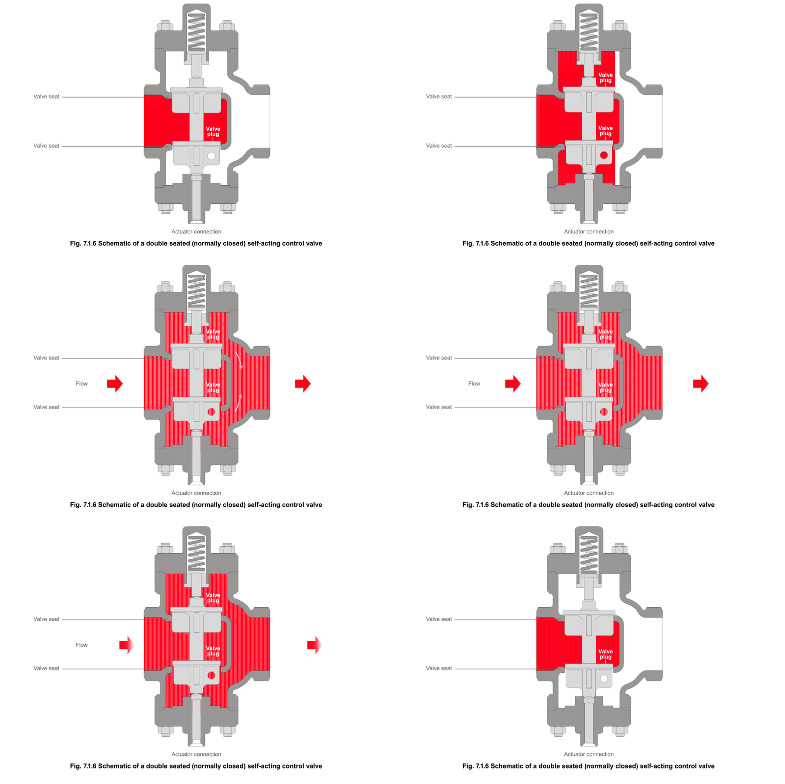
Double-seated control valves are useful when high capacity flow is required and tight shut-off is not needed. They can close against higher differential pressures than single seated valves of the same size. This is because the control valve comprises two valve plugs on a common spindle with two corresponding seats, as shown in Figure 7.1.6. The forces acting on the two valve plugs are almost balanced. Although the differential pressure is trying to keep one plug off its seat, it is pushing the other plug onto its seat.
However, the tolerances necessary to manufacture the component parts of the control valve make it difficult to achieve a tight shut-off. This is not helped by the lower valve plug and seat being smaller than its upper counterpart, which enables removal of the whole assembly for servicing.
Also, although the body and the valve shuttle are the same material, small variations in the chemistry of the individual parts can result in subtle variations in the coefficients of expansion, which adversely affects shut-off. A double-seated control valve should not be used as a safety device with a high limit safeguard.
 Control valves with internal fixed bleed holes
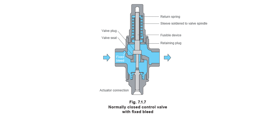
A normally closed valve will usually require a fixed bleed (Figure 7.1.7) to allow a small amount of flow through the control valve when it is fully shut. Normally closed self-acting control valves are sometimes referred to as being reverse acting (RA).
Control valves with internal fixed bleed holes
A normally closed valve will usually require a fixed bleed (Figure 7.1.7) to allow a small amount of flow through the control valve when it is fully shut. Normally closed self-acting control valves are sometimes referred to as being reverse acting (RA).
A typical application for this type of valve is to control the flow of cooling water (coolant) for an industrial engine such as an air compressor (Figure 7.1.8). The control valve, controlling the flow of coolant through the engine, is upstream of the engine and the temperature sensor registers its temperature as it leaves the engine.
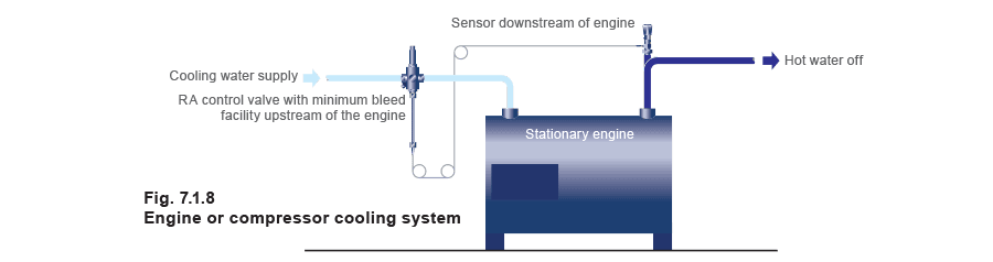 If the coolant leaving the engine is hotter than the set point, the control valve opens to allow more coolant through the valve. However, once the water leaving the engine reaches the required set temperature the valve will shut again. Without a bleedhole, the coolant would no longer flow and would continue to pick up heat from the engine. Without the downstream sensor detecting any temperature rise, the engine is likely to overheat.
If the control valve has a fixed diameter bleed hole, enough cooling water can flow through the valve to allow the downstream sensor to register a representative temperature when the valve is shut. This feature is essential when the sensor is remote from the application heat source.
A normally closed valve might also have an optional fusible device (see Figure 7.1.7). The device melts in the event of excess heat, removing the spring tension on the valve plug and opening the valve to allow the cooling water to enter the system. It is usual with this kind of safety device, that once the fusible device has melted, it cannot be repaired and must be replaced.
Three-port control valves
****Most of the control valves used with self-acting control systems are two-port. However, Figure 7.1.9 illustrates a self-acting piston type three-port control valve. The advantage of this type of valve design allows the same valve to be used for either mixing or diverting water applications; this is not normally the case with valves requiring electric or pneumatic actuators.
If the coolant leaving the engine is hotter than the set point, the control valve opens to allow more coolant through the valve. However, once the water leaving the engine reaches the required set temperature the valve will shut again. Without a bleedhole, the coolant would no longer flow and would continue to pick up heat from the engine. Without the downstream sensor detecting any temperature rise, the engine is likely to overheat.
If the control valve has a fixed diameter bleed hole, enough cooling water can flow through the valve to allow the downstream sensor to register a representative temperature when the valve is shut. This feature is essential when the sensor is remote from the application heat source.
A normally closed valve might also have an optional fusible device (see Figure 7.1.7). The device melts in the event of excess heat, removing the spring tension on the valve plug and opening the valve to allow the cooling water to enter the system. It is usual with this kind of safety device, that once the fusible device has melted, it cannot be repaired and must be replaced.
Three-port control valves
****Most of the control valves used with self-acting control systems are two-port. However, Figure 7.1.9 illustrates a self-acting piston type three-port control valve. The advantage of this type of valve design allows the same valve to be used for either mixing or diverting water applications; this is not normally the case with valves requiring electric or pneumatic actuators.
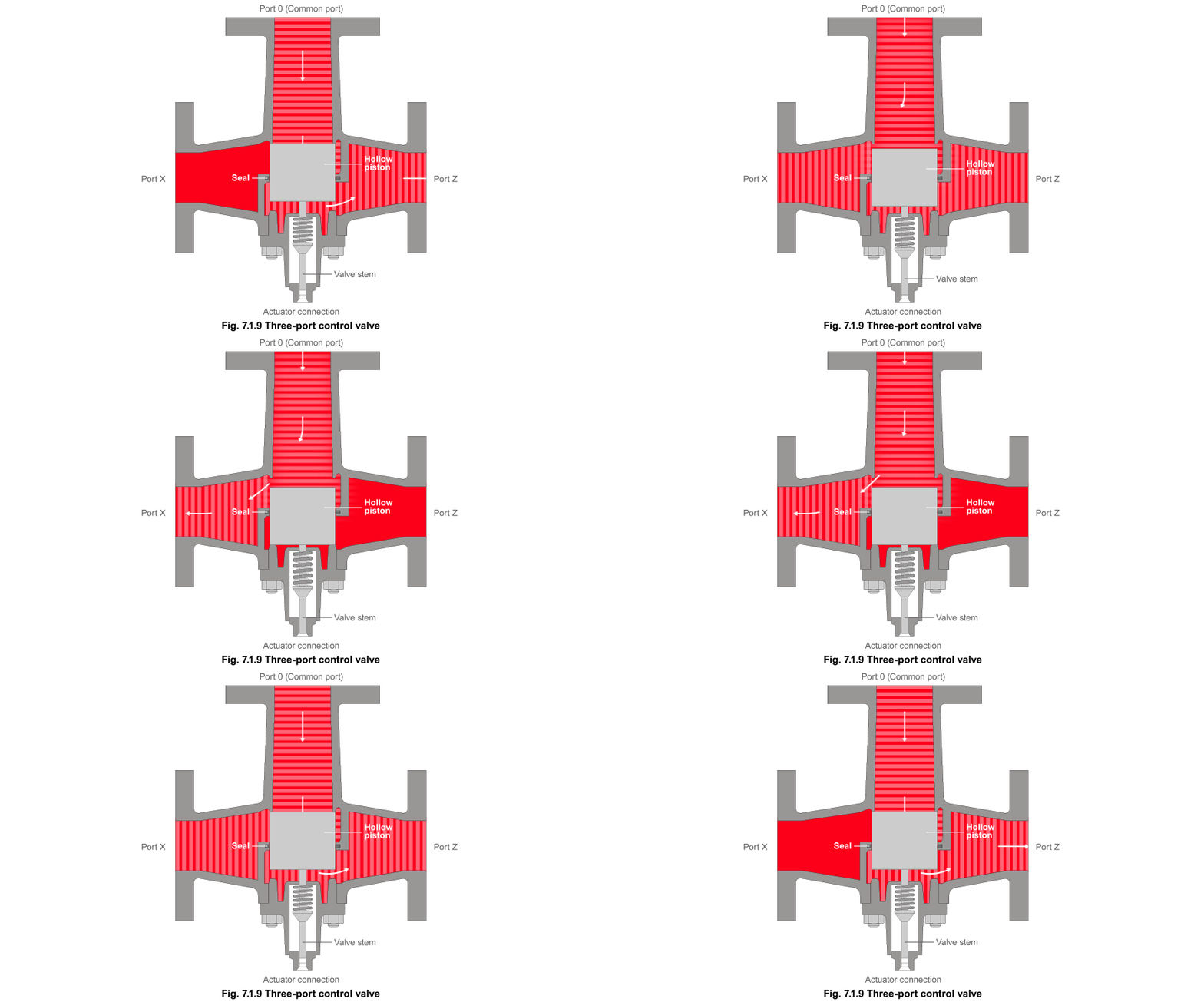
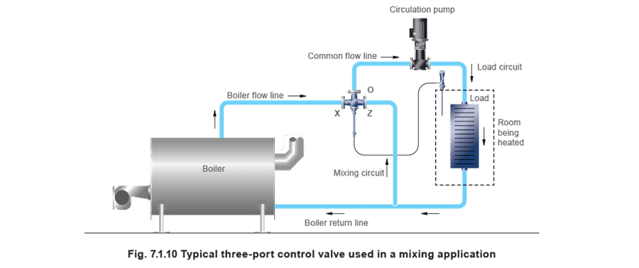
The most common applications are for water heating, but three-port control valves may also be used on cooling applications such as air chillers, and on pumped circuits in heating, ventilating and air conditioning applications. When a three-port control valve is used as a mixing valve (see Figure 7.1.10), the constant volume port ‘O’ is used as the common outlet.
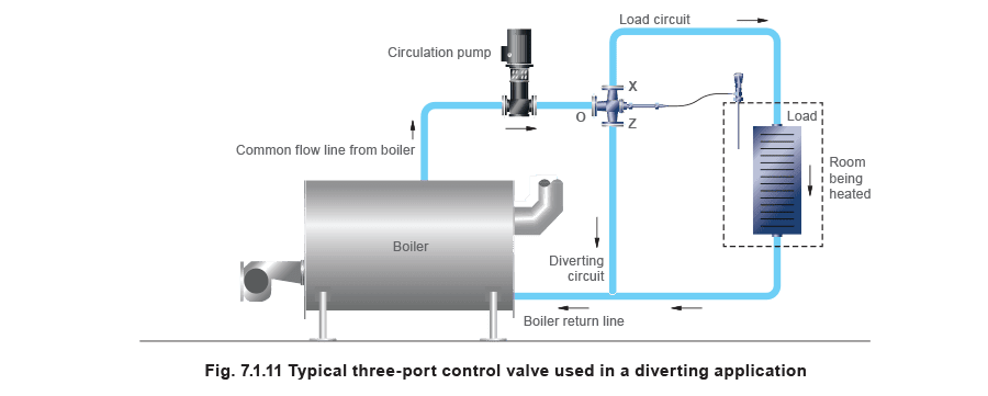
When a three-port control valve is used as a diverting valve (see Figure 7.1.11), the constant volume port is used as the common inlet.
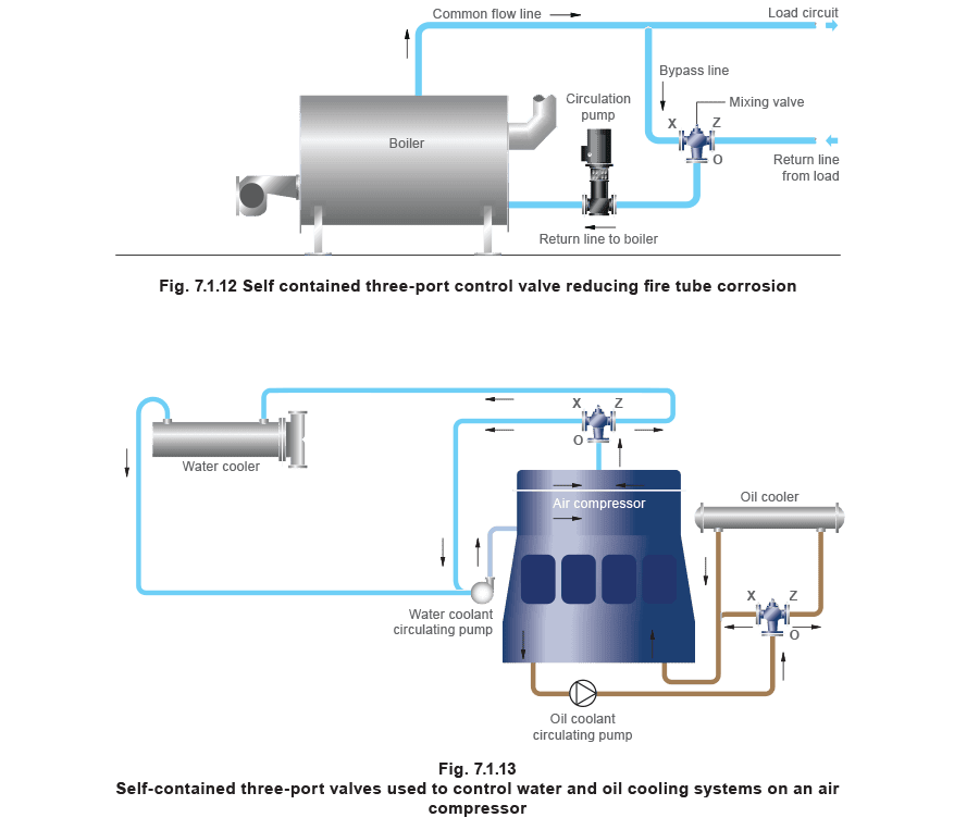
 Self-contained three port control valve
Another type of three-port self-acting control valve contains an integral temperature sensing device and thus requires no external temperature controller to operate.
It can be used to protect Low Temperature Hot Water (LTHW) boilers from fire tube corrosion during start-up sequences when the temperature of the secondary return water is low (see Figure 7.1.12). At start-up, the valve allows cold secondary water to bypass the external system and flow through the boiler circuit. This allows water in the boiler to heat up quickly, minimising the condensation of water vapour in the flue gases. As the boiler water heats up, it is slowly blended with water from the main system, thus maintaining protection while the complete system is brought slowly up to temperature.
This type of control valve may also be used on cooling systems such as those found on air compressors (Figure 7.1.13).