Controles de Pressão Auto-acionados e Aplicações
Vários tipos de controles de pressão auto-acionados são examinados neste tutorial, incluindo válvulas operadas por fole e diafragma de ação direta, e válvulas operadas por piloto, com diretrizes sobre como selecioná-las e instalá-las corretamente. Válvulas redutoras de pressão são consideradas juntamente com válvulas de manutenção de pressão e válvulas de sobra, ao lado de algumas aplicações típicas.
Por que reduzir a pressão do vapor?
Por que reduzir a pressão do vapor?
A razão principal para reduzir a pressão do vapor é bastante fundamental. Cada item de equipamento que usa vapor tem uma pressão de trabalho máxima admissível (MAWP). Se esta for menor que a pressão de suprimento de vapor, uma válvula redutora de pressão deve ser empregada para limitar a pressão de suprimento à MAWP. No caso de a válvula redutora de pressão falhar, uma válvula de segurança também deve ser incorporada ao sistema. Este não é, no entanto, o único momento em que uma válvula redutora de pressão pode ser usada com vantagem.
A maioria das caldeiras de vapor são projetadas para trabalhar em pressões relativamente altas e não devem ser operadas em pressões mais baixas, pois vapor úmido é provável de ser produzido. Por esta razão, é geralmente mais econômico a longo prazo produzir e distribuir vapor em uma pressão mais alta, e reduzir a pressão a montante de quaisquer itens de planta projetados para operar em uma pressão mais baixa.
Este tipo de arranjo tem a vantagem adicional de que tubulações de distribuição relativamente menores podem ser usadas devido ao volume relativamente pequeno ocupado pelo vapor em alta pressão.
Uma vez que a temperatura do vapor saturado está intimamente relacionada à sua pressão, o controle de pressão pode ser um método simples, mas eficaz, de fornecer controle preciso de temperatura. Este fato é usado com bom efeito em aplicações como esterilizadoras e secadores de contato, onde o controle da temperatura superficial é difícil de achieves usando sensores de temperatura. Planta operando em baixa pressão de vapor -
- Pode tender a reduzir a quantidade de vapor produzido pela caldeira devido à maior entalpia de evaporação no vapor de menor pressão.
- Reduzirá a perda de vapor flash produzido a partir de ventilações abertas em tanques coletores de condensado. A maioria das válvulas redutoras de pressão atualmente disponíveis pode ser dividida nos seguintes dois grupos principais -
- Válvulas de ação direta.
- Válvulas operadas por piloto.
Válvulas de ação direta
Válvulas de ação direta
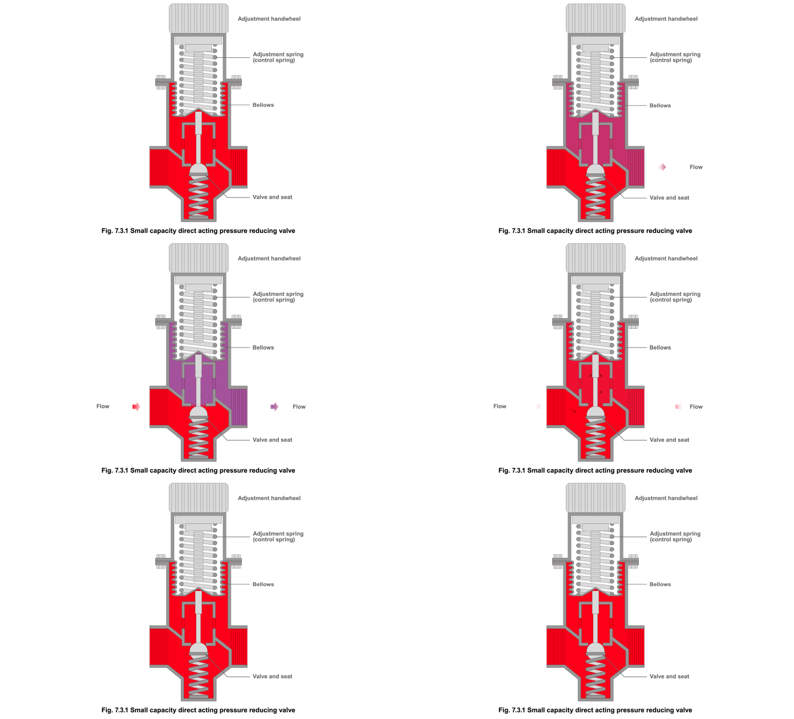
Smaller capacity direct acting pressure reducing valves (Figure 7.3.1) Method of operation On start-up and with the adjustment spring relaxed, upstream pressure, aided by a return spring, holds the valve head against the seat in the closed position. Rotating the handwheel in a clockwise direction causes a downward movement, which compresses the control spring and extends the bellows to set the downstream pressure. This downward movement is transmitted via a pushrod, which causes the main valve to open. Steam then passes through the open valve into the downstream pipework and surrounds the bellows. As downstream pressure increases, it acts through the bellows to counteract the adjustment spring force, and closes the main valve when the set pressure is reached. The valve plug modulates in an attempt to achieve constant pressure. In order to close the valve, there must be a build-up of pressure around the bellows. This requires an increase in downstream pressure above the set pressure in proportion to the steam flow. The downstream pressure will increase as the load falls and will be highest when the valve is closed. This change in pressure relative to a change in load means that the downstream pressure will only equal the set pressure at one load. The actual downstream pressure compared to the set point is the proportional offset; it will increase relative to the load, and this is sometimes referred to as ‘droop’. The total pressure available to close the valve consists of the downstream pressure acting on the underside of the bellows plus the inlet pressure acting on the underside of the main valve itself and the small force produced by the return spring. The control spring force must therefore be larger than the reduced pressure and inlet pressure and return spring for the downstream pressure to be set. Any variation in the inlet pressure will alter the force it produces on the main valve and so affect the downstream pressure. This type of pressure reducing valve has two main drawbacks in that -
- It suffers from proportional offset as the steam flow changes
- It has relatively low capacity.
It is nevertheless perfectly adequate for a substantial range of simple applications where accurate control is not essential and where steam flow is fairly small and reasonably constant.
 Larger capacity direct acting pressure reducing valves (Figure 7.3.2)
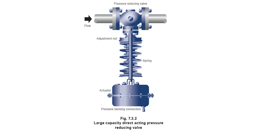
****Larger capacity direct acting pressure reducing valves are also available for use on larger capacity plant, or on steam distribution mains. They differ slightly to the smaller capacity valves in that the actuator force is provided by pressure acting against a flexible diaphragm inside the actuator rather than a bellows.
As these are not pilot-operated, they will incur a change in downstream pressure as the steam flow changes, and this should be taken into careful consideration when selecting and sizing the valve.
Larger capacity direct acting pressure reducing valves (Figure 7.3.2)
****Larger capacity direct acting pressure reducing valves are also available for use on larger capacity plant, or on steam distribution mains. They differ slightly to the smaller capacity valves in that the actuator force is provided by pressure acting against a flexible diaphragm inside the actuator rather than a bellows.
As these are not pilot-operated, they will incur a change in downstream pressure as the steam flow changes, and this should be taken into careful consideration when selecting and sizing the valve.
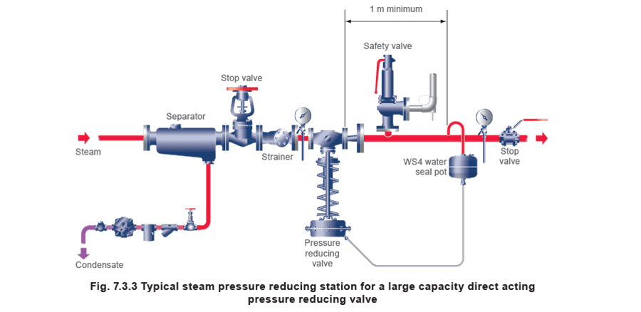
 This type of valve is installed with the actuator below the pipe when used with steam, and has a water seal pot to stop high steam temperatures from reaching and damaging the actuator’s flexible diaphragm, which is commonly made out of neoprene. A typical installation for the reduction of steam mains pressure is shown in Figure 7.3.3.
Válvulas operadas por piloto
Válvulas operadas por piloto
Where accurate control of pressure or a large flow capacity is required, a pilot-operated pressure reducing valve can be used. Such a valve is shown schematically in Figure 7.3.4. A pilot-operated pressure reducing valve will usually be smaller than a direct acting valve of the same capacity.
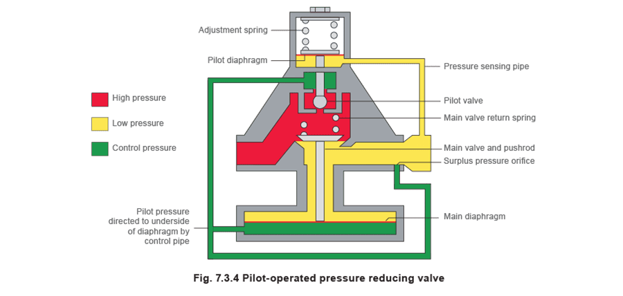 A pilot-operated pressure reducing valve works by balancing the downstream pressure via a pressure sensing pipe against a pressure adjustment control spring. This moves a pilot valve to modulate a control pressure. The control pressure transmitted via the pilot valve is proportional to the pilot valve opening, and is directed, via the control pipe to the underside of the main valve diaphragm.
The diaphragm moves the pushrod and the main valve in proportion to the movement of the pilot valve. Although the downstream pressure and pilot valve position are proportional (as in the direct acting valve), the mechanical advantage given by the ratio of the areas of the main diaphragm to the pilot diaphragm offers accuracy with small proportional offset.
Under stable load conditions, the pressure under the pilot diaphragm balances the force set on the adjustment spring. This settles the pilot valve, allowing a constant pressure under the main diaphragm. This ensures that the main valve is also settled, giving a stable downstream pressure.
When downstream pressure rises, the pressure under the pilot diaphragm is greater than the force created by the adjustment spring and the pilot diaphragm moves up.
This closes the pilot valve and interrupts the transmission of steam pressure to the underside of the main diaphragm. The top of the main diaphragm is subjected to downstream pressure at all times and, as there is now more pressure above the main diaphragm than below, the main diaphragm moves down pushing the steam underneath into the downstream pipework via the control pipe and surplus pressure orifice. The pressure either side of the main diaphragm is balanced, and a small excess force created by the main valve return spring closes the main valve.
Any variations in load or pressure will immediately be sensed on the pilot diaphragm, which will act to adjust the position of the main valve accordingly, ensuring a constant downstream pressure.
The pilot-operated design offers a number of advantages over the direct acting valve. Only a very small amount of steam has to flow through the pilot valve to pressurise the main diaphragm chamber and fully open the main valve. Thus only very small changes in control pressure are necessary to produce large changes in flow. The fall in downstream pressure relative to changes in steam flow is therefore small, typically less than three hundredths of a bar (3 kPa; 0.5 psi) from fully open to fully closed.
Although any rise in upstream pressure will apply an increased closing force on the main valve, the same rise in pressure will act on the underside of the main diaphragm and will balance the effect.
The result is a valve which gives close control of downstream pressure regardless of variations on the upstream side.
A pilot-operated pressure reducing valve works by balancing the downstream pressure via a pressure sensing pipe against a pressure adjustment control spring. This moves a pilot valve to modulate a control pressure. The control pressure transmitted via the pilot valve is proportional to the pilot valve opening, and is directed, via the control pipe to the underside of the main valve diaphragm.
The diaphragm moves the pushrod and the main valve in proportion to the movement of the pilot valve. Although the downstream pressure and pilot valve position are proportional (as in the direct acting valve), the mechanical advantage given by the ratio of the areas of the main diaphragm to the pilot diaphragm offers accuracy with small proportional offset.
Under stable load conditions, the pressure under the pilot diaphragm balances the force set on the adjustment spring. This settles the pilot valve, allowing a constant pressure under the main diaphragm. This ensures that the main valve is also settled, giving a stable downstream pressure.
When downstream pressure rises, the pressure under the pilot diaphragm is greater than the force created by the adjustment spring and the pilot diaphragm moves up.
This closes the pilot valve and interrupts the transmission of steam pressure to the underside of the main diaphragm. The top of the main diaphragm is subjected to downstream pressure at all times and, as there is now more pressure above the main diaphragm than below, the main diaphragm moves down pushing the steam underneath into the downstream pipework via the control pipe and surplus pressure orifice. The pressure either side of the main diaphragm is balanced, and a small excess force created by the main valve return spring closes the main valve.
Any variations in load or pressure will immediately be sensed on the pilot diaphragm, which will act to adjust the position of the main valve accordingly, ensuring a constant downstream pressure.
The pilot-operated design offers a number of advantages over the direct acting valve. Only a very small amount of steam has to flow through the pilot valve to pressurise the main diaphragm chamber and fully open the main valve. Thus only very small changes in control pressure are necessary to produce large changes in flow. The fall in downstream pressure relative to changes in steam flow is therefore small, typically less than three hundredths of a bar (3 kPa; 0.5 psi) from fully open to fully closed.
Although any rise in upstream pressure will apply an increased closing force on the main valve, the same rise in pressure will act on the underside of the main diaphragm and will balance the effect.
The result is a valve which gives close control of downstream pressure regardless of variations on the upstream side.
In some types of pilot-operated valve, a piston replaces the main diaphragm. This can be advantageous in bigger valves, which would require very large size main diaphragms. However, problems with the piston sticking in its cylinder are common, particularly in smaller valves. It is important for a strainer and separator to be installed immediately prior to any pilot-operated control valve, as clean dry steam will prolong its service life.
Seleção e instalação de válvulas redutoras de pressão
Seleção e instalação de válvulas redutoras de pressão
The first essential is to select the best type of valve for a given application.
Small loads where accurate control is not vital should be met by using simple direct acting valves. In all other cases, the pilot-operated valve is the best choice, particularly if there are periods of no demand when the downstream pressure must not be allowed to rise.
Oversizing should be avoided with all types of control valve and this is equally true of reducing valves. A valve plug working close to its seat when passing wet steam can suffer wiredrawing and premature erosion. In addition, any small movement of the oversized valve plug will produce a relatively large change in the flow through the valve, making it more difficult for the valve to control accurately.
A smaller, correctly sized reducing valve will be less prone to wear and will provide more accurate control. Where it is necessary to make big reductions in pressure or to cope with wide fluctuations in load, it may be preferable to use two or more valves in series or in parallel.
Although reliability and accuracy depend on correct selection and sizing, pressure reducing valves also depend on correct installation. Figure 7.3.5 illustrates an ideal arrangement for the installation of a pilot-operated pressure reducing valve.
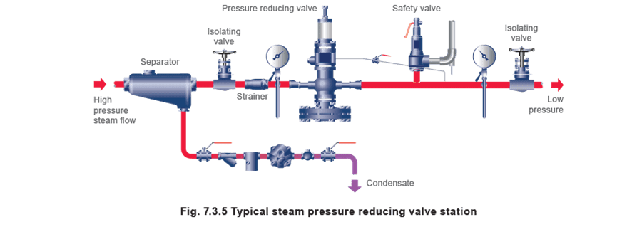 Many reducing valve problems are caused by the presence of moisture or dirt. A steam separator and strainer with fine mesh screen, if fitted before the valve, will help to prevent such problems. The strainer is fitted on its side to prevent the body filling with water and to ensure that the full area of the screen is effective. Large isolation valves will also benefit from being installed on their side for the same reason.
All upstream and downstream pipework and fittings must be adequately sized to ensure that the only appreciable pressure drop occurs across the reducing valve itself. If the isolating valves are the same size as the reducing valve connections, they will incur a larger pressure drop than if they are sized to match the correctly sized, larger diameters of the upstream and downstream pipework.
Many reducing valve problems are caused by the presence of moisture or dirt. A steam separator and strainer with fine mesh screen, if fitted before the valve, will help to prevent such problems. The strainer is fitted on its side to prevent the body filling with water and to ensure that the full area of the screen is effective. Large isolation valves will also benefit from being installed on their side for the same reason.
All upstream and downstream pipework and fittings must be adequately sized to ensure that the only appreciable pressure drop occurs across the reducing valve itself. If the isolating valves are the same size as the reducing valve connections, they will incur a larger pressure drop than if they are sized to match the correctly sized, larger diameters of the upstream and downstream pipework.
If the downstream pipework or any connected plant is incapable of withstanding the maximum possible upstream pressure, then a safety valve or relief valve must be fitted on the downstream side. This valve should be set at, or below, the maximum allowable working pressure of the equipment, but with a sufficient margin above its normal operating pressure. It must be capable of handling the full volume of steam that could pass through the fully open reducing valve, at the maximum possible upstream pressure.
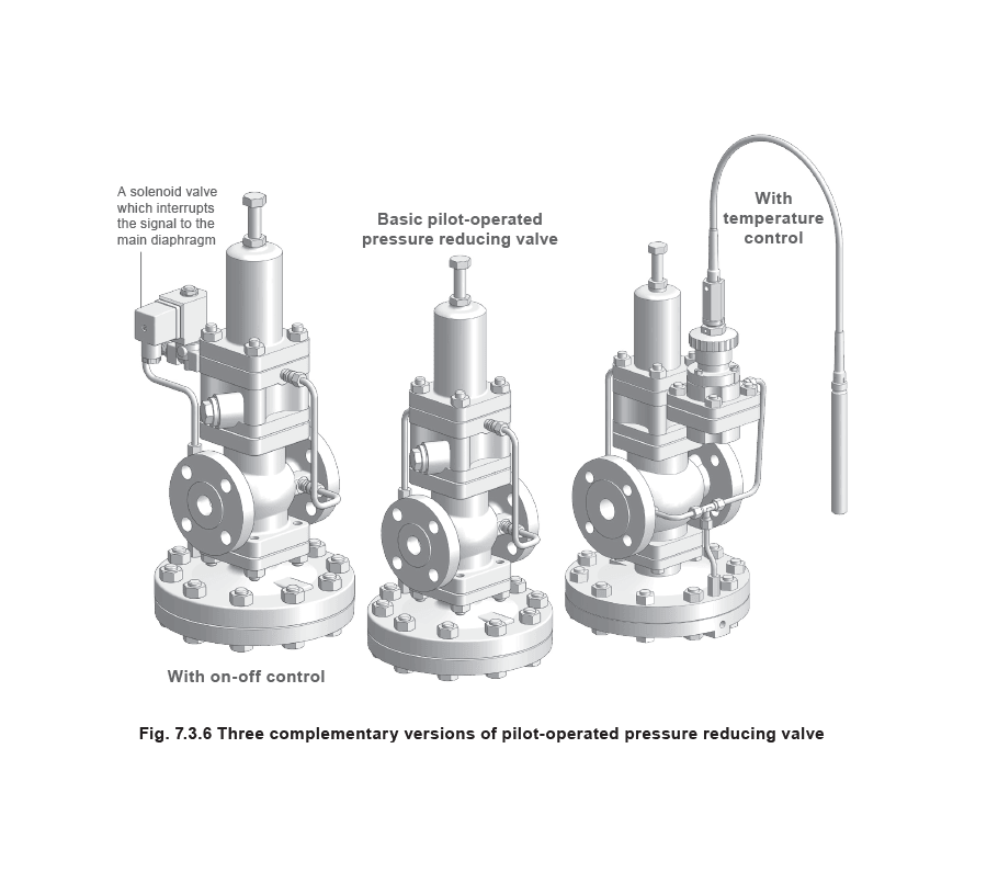
Pilot operation also allows the reducing valve to be relatively compact compared to other valves of similar capacity and accuracy, and allows a variety of control options, such as on-off operation, dual pressure control, pressure and temperature control, pressure reducing and surplussing control, and remote manual adjustment. Three of these variations can be seen in Figure 7.3.6.
Direct acting and pilot-operated control valves can be used to control either upstream or downstream pressures. Pressure maintaining valves (and surplussing valves) sense upstream pressure, while pressure reducing valves sense downstream pressure.
Resumo das válvulas redutoras de pressão
Resumo das válvulas redutoras de pressão
A valve that senses and controls the downstream pressure is often referred to as a ‘let-down’ valve or ‘pressure reducing valve’ (PRV). Such valves can be used to maintain constant steam pressure onto a control valve, a steam flowmeter, or directly onto a process.
Pressure reducing valves are selected on capacity and type of application.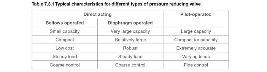
Válvulas de manutenção de pressão
Válvulas de manutenção de pressão
Some applications require that upstream pressure is sensed and controlled and this type of valve is often referred to as a ‘Pressure Maintaining Valve’ or ‘PMV’. Pressure maintaining valves are also known as surplussing valves or spill valves in certain applications.
An example of a PMV application would be where steam generation plant is undersized, and yet steam flow is critical to the process. If steam demand is greater than the boiler output, or suddenly rises when the boiler burner is off, the boiler pressure will drop; progressively wetter steam will be supplied to the plant and the boiler operation may be jeopardised. If the boiler can operate at its design pressure, optimum steam quality will be maintained.
This can be achieved by fitting PMVs on each non-critical application (perhaps heating plant or domestic hot water plant), thereby introducing a controlled diversity to the plant. These will then progressively shut down if upstream pressure falls, giving priority to essential services. Should all supplies be considered essential, a variety of options are available, each of which has a different cost implication.
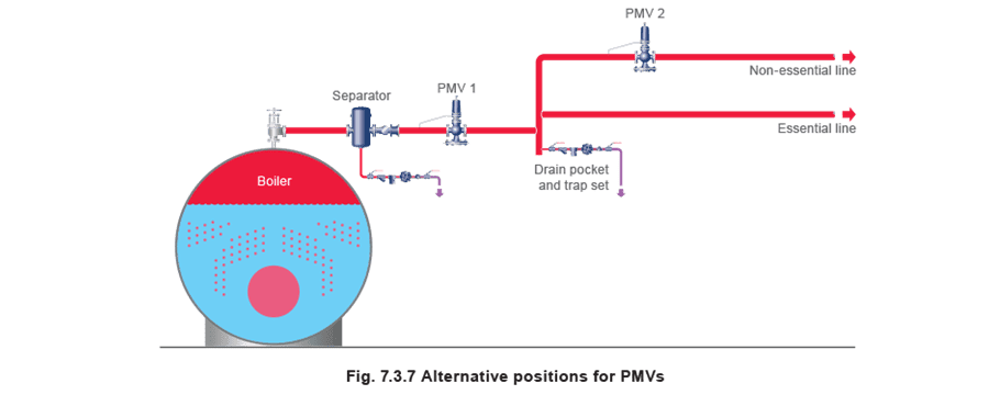
The cheapest solution might be to fit a PMV in the boiler steam outlet, (see PMV 1 in Figure 7.3.7). This will maintain a minimum steam pressure in the boiler, regulate maximum flow from the boiler and, in so doing, retain good quality steam to the plant.
If it is possible to shut off non-essential equipment during times of peak loading, PMVs can be installed in distribution lines or branch lines supplying these areas of the plant. When the steam boiler becomes overloaded, the non-essential supplies are gradually shut down by PMV 2 allowing the boiler to maintain steam flow to the ‘essential’ plant at the proper pressure.
 It should be recognised that a PMV will not always cure the problems caused by insufficient boiler capacity. Sometimes, when there is little plant diversity, only one real alternative is available, which is to increase the generating capacity by adding another boiler.
However, there are occasions when the cheaper alternative of a steam accumulator is possible. This allows excess boiler energy to be stored during periods of low load. When the boiler is overloaded, the accumulator augments the boiler output by allowing a controlled release of steam to the plant (see Figure 7.3.8).
In Figure 7.3.8, the boiler is designed to generate steam at 10 bar g, which is distributed at both 10 bar g and 5 bar g to the rest of the plant.
PRV 1 is a pressure reducing valve, and is sized to pass the boiler capacity minus the high pressure steam load.
It should be recognised that a PMV will not always cure the problems caused by insufficient boiler capacity. Sometimes, when there is little plant diversity, only one real alternative is available, which is to increase the generating capacity by adding another boiler.
However, there are occasions when the cheaper alternative of a steam accumulator is possible. This allows excess boiler energy to be stored during periods of low load. When the boiler is overloaded, the accumulator augments the boiler output by allowing a controlled release of steam to the plant (see Figure 7.3.8).
In Figure 7.3.8, the boiler is designed to generate steam at 10 bar g, which is distributed at both 10 bar g and 5 bar g to the rest of the plant.
PRV 1 is a pressure reducing valve, and is sized to pass the boiler capacity minus the high pressure steam load.
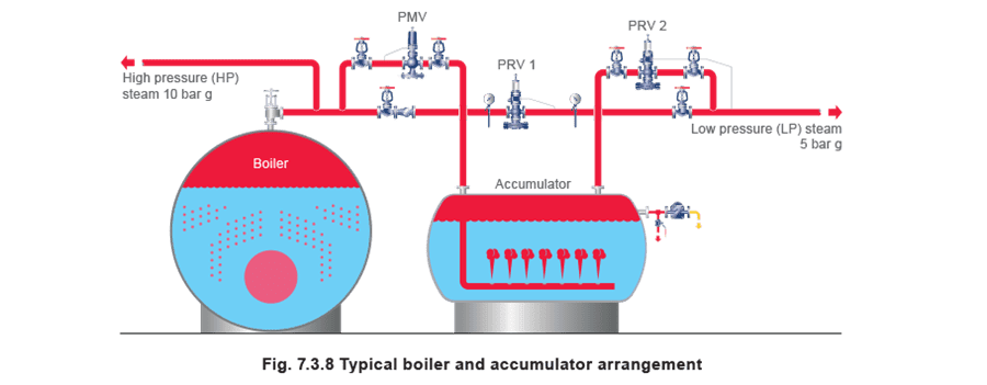 For sizing purposes, the capacity of the pressure reducing valve PRV 2 should equal the maximum discharge rate and time for which the accumulator has been designed to operate, whilst the differential pressure for design purposes should be the difference between the minimum operating accumulator pressure and the LP (Low pressure) distribution pressure. In this example, PRV 2 would probably be set to open at about 4.8 bar g.
PMV is a pressure maintaining valve whose size is determined by the recharging time required by the accumulator and the available surplus boiler capacity during recharging. When recharging, the pressure drop across the PMV is likely to be relatively small, so the PMV is likely to be quite large, typically the same size as the line in which it is installed. The PMV is usually set to operate just below the boiler maximum pressure setting.
When the total plant load is within the boiler capacity, PRV 2 is shut and the boiler supplies the LP steam load through PRV 1 which is set to control slightly higher than PRV2. Any excess steam available in the boiler will cause the boiler pressure to rise above the PMV set point, and the PMV will open to recharge the accumulator. Recharging will continue until the accumulator pressure equals the boiler pressure, or until the plant load is such that the boiler pressure again drops below the PMV set point.
Should the LP steam load continue to increase, causing the LP pressure to drop below PRV 2 set point, PRV 2 will open to provide steam from the accumulator, in turn supplementing the steam flowing through PRV 1.
There is more than one way in which to design an accumulator installation; each will depend upon the circumstances involved, and will have a cost implication. The subject of accumulators is discussed in more detail in Module 3.22 ‘Steam accumulators’.
For sizing purposes, the capacity of the pressure reducing valve PRV 2 should equal the maximum discharge rate and time for which the accumulator has been designed to operate, whilst the differential pressure for design purposes should be the difference between the minimum operating accumulator pressure and the LP (Low pressure) distribution pressure. In this example, PRV 2 would probably be set to open at about 4.8 bar g.
PMV is a pressure maintaining valve whose size is determined by the recharging time required by the accumulator and the available surplus boiler capacity during recharging. When recharging, the pressure drop across the PMV is likely to be relatively small, so the PMV is likely to be quite large, typically the same size as the line in which it is installed. The PMV is usually set to operate just below the boiler maximum pressure setting.
When the total plant load is within the boiler capacity, PRV 2 is shut and the boiler supplies the LP steam load through PRV 1 which is set to control slightly higher than PRV2. Any excess steam available in the boiler will cause the boiler pressure to rise above the PMV set point, and the PMV will open to recharge the accumulator. Recharging will continue until the accumulator pressure equals the boiler pressure, or until the plant load is such that the boiler pressure again drops below the PMV set point.
Should the LP steam load continue to increase, causing the LP pressure to drop below PRV 2 set point, PRV 2 will open to provide steam from the accumulator, in turn supplementing the steam flowing through PRV 1.
There is more than one way in which to design an accumulator installation; each will depend upon the circumstances involved, and will have a cost implication. The subject of accumulators is discussed in more detail in Module 3.22 ‘Steam accumulators’.
Válvulas de sobra de pressão
Válvulas de sobra de pressão
The ability to sense upstream pressure may be used to release surplus pressure from a steam system in a controlled and safe manner. The surplussing valve is essentially the same as a PMV, opening when an increase in upstream pressure is sensed. The surplussing valve is sometimes referred to as a ‘dump’ valve when releasing steam to atmosphere.
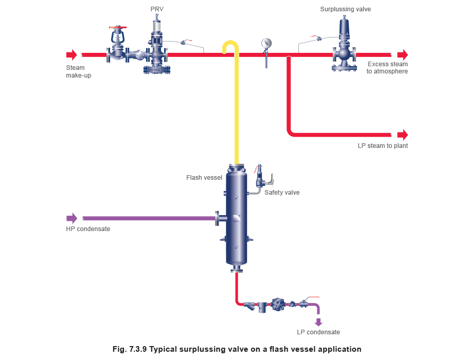
A ‘surplussing valve’ is often used to control the maximum pressure in a flash recovery system. Should the demand for flash steam be less than the available supply, the flash pressure will rise and the surplussing valve will open to release any excess steam to atmosphere. The surplussing valve will be set to operate at a pressure below the safety valve setting.
Important: Whilst this allows the controlled release of steam to atmosphere, it does not replace the need for a safety valve, should the plant conditions require it.
In Figure 7.3.9 the PRV replenishes any shortfall of flash steam generated by the high pressure (HP) condensate, and the surplussing valve releases any excess flash steam to either a condenser or to atmosphere.
The safety valve is sized on the full capacity of the PRV plus the capacity of the steam traps and any other source feeding into the flash vessel.