

layout ของท่อ return คอนเดนเสท
ข้อพิจารณา surrounding การออกแบบและ layout ของท่อ return คอนเดนเสท รวมถึงท่อ drain ไปยังกับดักไอน้ำ ท่อ discharge จากกับดัก ท่อ return ร่วม และท่อ return แบบสูบ รวมถึงผลกระทบของประเภทกับดักที่ใช้ ผลกระทบของแรงดันที่แตกต่างกัน และการ discharge คอนเดนเสทเข้าท่อ mains ที่ท่วม
layout ของท่อ return คอนเดนเสท
layout ของท่อ return คอนเดนเสท
ไม่มีชุดคำแนะนำเดียวที่สามารถครอบคลุม layout ของท่อคอนเดนเสท หลายอย่างขึ้นอยู่กับแรงดัน application ลักษณะเฉพาะของกับดักไอน้ำ ตำแหน่งของท่อ return คอนเดนเสท relative to โรงงาน และแรงดันในท่อ return คอนเดนเสท ด้วยเหตุนี้ best to start โดยพิจารณาสิ่งที่ต้อง achieve และออกแบบ layout ที่ will ensure ว่า best practice พื้นฐานได้รับการ meet วัตถุประสงค์หลักคือ:
- คอนเดนเสท must not be allowed to accumulate ในโรงงาน unless อุปกรณ์ที่ใช้ไอน้ำ specifically designed to operate in way นี้ โดยทั่วไปอุปกรณ์ designed to operate nonflooded และ where this is the case คอนเดนเสทที่ accumulated will inhibit performance และ encourage การกัดกร่อนของท่อ fittings และอุปกรณ์
- คอนเดนเสท must not be allowed to accumulate ในท่อไอน้ำหลัก ที่นี่ can be picked up by ไอน้ำ velocity สูง leading to erosion และ waterhammer ในท่อ เรื่องของท่อคอนเดนเสท will divide naturally into สี่ประเภทพื้นฐาน where ข้อกำหนดและข้อพิจารณาของ each will differ สี่ประเภทพื้นฐานนี้ defined และ illustrated ในรูปที่ 14.2.1
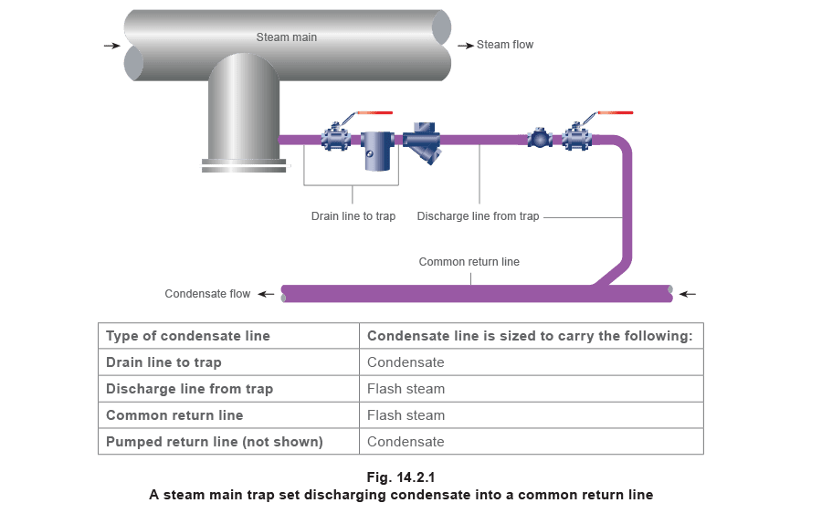
ท่อ drain ไปยังกับดักไอน้ำ
ท่อ drain ไปยังกับดักไอน้ำ
ในท่อ drain คอนเดนเสทและก๊าซที่ไม่ condense ต้อง flow จาก drain outlet ของโรงงานไปยังกับดักไอน้ำ ในท่อ drain ที่ sized correctly โรงงานที่กำลัง drain และ body ของกับดักไอน้ำ virtually at แรงดันเดียวกัน และ because of this คอนเดนเสท does not flash ในท่อนี้ Gravity คือ driving force และ relied upon to induce flow along ท่อ ด้วยเหตุนี้ สมเหตุสมผลที่กับดัก situated below outlet ของโรงงานที่กำลัง drain และท่อกับดัก discharge terminate below กับดัก (ข้อยกเว้น for this is tank heating coils discussed ใน Module 2.10) ประเภทของกับดักไอน้ำที่ใช้ (เทอร์โมสแตติก เทอร์โมไดนามิก หรือกลไก) สามารถส่งผลต่อ layout ท่อ กับดักไอน้ำเทอร์โมสแตติก Thermostatic traps will cool คอนเดนเสท below อุณหภูมิอิ่มตัวก่อน discharge นี่ effectively waterlogs ท่อ drain often allowing คอนเดนเสท to back-up และ flood โรงงาน มี applications บางอย่างที่ sub-cooling ของคอนเดนเสทมีข้อดี significant และ encouraged ไอน้ำแฟลช produced น้อยกว่าในท่อ discharge กับดัก และการแนะนำคอนเดนเสทเข้าท่อคอนเดนเสทหลัก gentler Thermostatic traps discharging via ท่อ open-ended will waste พลังงานน้อยกว่า mechanical traps because more ของ sensible heat ในคอนเดนเสท waterlogged imparts ความร้อนให้กระบวนการ; ตัวอย่าง typical คือ steam tracer line Thermostatic traps should not be used to drain ท่อไอน้ำหลักหรือ heat exchangers unless proper consideration given to ท่อ drain ที่ยาวกว่าและ/หรือใหญ่กว่า to act as reservoir และ dissipate ความร้อน to atmosphere ความยาวพิเศษ (or larger diameter) ของท่อ drain ที่ required to do this usually impractical as shown in Example 14.2.1 ตัวอย่าง 14.2.1 เครื่องทำความร้อนอากาศ 30 kW จะ fit ด้วยกับดักไอน้ำเทอร์โมสแตติก DN15 ที่ release คอนเดนเสทที่ 13°C ต่ำกว่าอุณหภูมิอิ่มตัว แรงดันทำงานปกติคือ 3 bar g อุณหภูมิแวดล้อมคือ 15°C และการสูญเสียความร้อนจากท่อ drain to environment estimated to be 20 W/m2 °C กำหนดความยาว minimum ที่ required ของท่อ drain 15 mm ไปยังกับดักเทอร์โมสแตติก From steam tables ที่ 3 bar g:
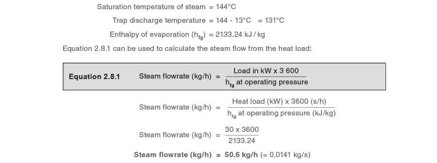
เนื่องจากกับดัก discharge ที่ 131°C ท่อ drain ต้อง emit ความร้อนเพียงพอ such that คอนเดนเสทที่ heater outlet อยู่ที่อุณหภูมิอิ่มตัว และคอนเดนเสทจะไม่ back-up เข้า heater ความร้อนที่ required ที่ loss จากท่อ drain สามารถคำนวณจากสมการ 2.6.5
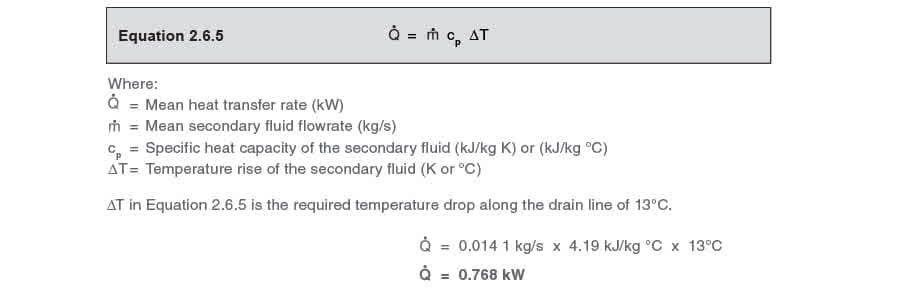
การสูญเสียความร้อนนี้จะ achieved จากอุณหภูมิเฉลี่ยของคอนเดนเสท along ท่อ drain อุณหภูมิเฉลี่ยของคอนเดนเสทในท่อ drain

พื้นผิวของท่อ drain เพื่อ provide การสูญเสียความร้อนที่ required สามารถคำนวณ using Equation 2.5.3

หมายเหตุ: will be อัตราการถ่ายเทความร้อนเฉลี่ย (Q̇M) if ΔT is อุณหภูมิเฉลี่ย (ΔTLM or ΔTAM)
ΔT ในสมการ 2.5.3 คือ difference between อุณหภูมิเฉลี่ยของคอนเดนเสทและอุณหภูมิแวดล้อม = 137.5°C - 15°C = 122.5°C Q = 0.768 kW U = 20 W/m2 °C From Equation 2.5.3 0.768 x 10³ watts = 20 watts/m2 °C x A x 122.5°C Therefore, A = 0.313 m2 ความยาวของท่อที่ required to provide พื้นผิวนี้ สามารถคำนวณ using information from Table 2.10.3
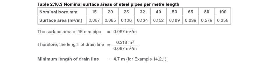
ความยาวของท่อนี้ (4.7 m) probably impractical in the field Two alternatives remain หนึ่งคือเพิ่มเส้นผ่านศูนย์กลางของท่อ drain which is still usually impractical; อีกอันง่ายกว่า much ที่ fit ถูกต้อง ถูกต้อง for this type of application; a float-thermostatic trap which discharges คอนเดนเสทที่อุณหภูมิไอน้ำ and hence requires no cooling leg
หากกับดักเทอร์โมสแตติก considered essential and fitted no more than 2 metres away from heater outlet it would be necessary to calculate required diameter of ท่อ drain การสูญเสียความร้อน required from ท่อ remains the same along with พื้นผิวรวมของท่อ but พื้นผิว per metre length must increase

พื้นผิว required/metre length = 0.157 m2 /m
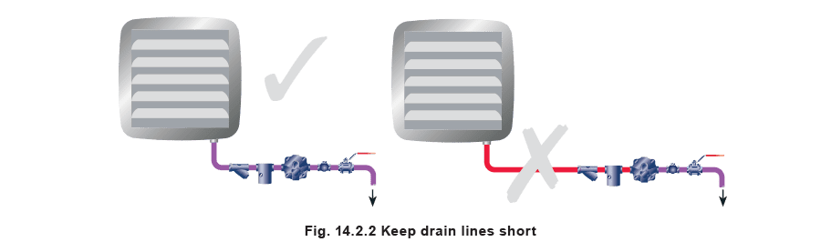
From Table 2.10.3, it can be seen that ท่อ sized ขั้นต่ำที่ give this area per metre is ท่อ 50 mm ซึ่ง again may be construed as being impractical and expensive to fabricate moral ของเรื่องนี้คือ usually easier and cheaper to select ถูกต้อง trap for the job than have wrong type of trap and fabricate solution around it กับดักไอน้ำเทอร์โมไดนามิก Traps that discharge intermittently such as thermodynamic traps will accumulate คอนเดนเสท between discharges However they are extremely robust will tolerate freezing ambient temperatures and have relatively small outer surface area meaning that heat loss to environment is minimized They are not suitable for discharging คอนเดนเสท into flooded return lines as will be explained later in this Block กับดักไอน้ำกล Mechanical steam traps with continuous discharge characteristic for example float-thermostatic traps often prove to be best option and have additional advantage of being able to vent air Most float traps are available in two basic flow configurations either horizontal or vertical flow through trap Some inverted bucket traps have bottom inlet and top outlet connections Clearly trap connections will affect path of connecting pipework ท่อ drain should be kept to minimum length ideally less than 2 metres Long drain lines from plant to steam trap can fill with steam and prevent คอนเดนเสท reaching trap This effect is termed steam locking To minimise this risk drain lines should be kept short (see Figure 14.2.2) In situations where long drain lines are unavoidable steam locking problem may be overcome using float traps with steam lock release devices Problem of steam locking should be tackled by fitting correct length of pipe in first place if possible
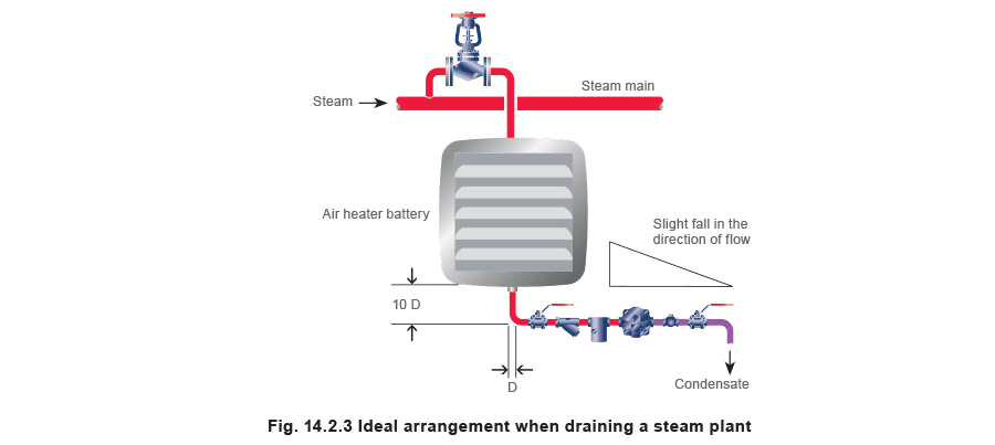
arrangements โดยละเอียดสำหรับ trapping steam-using plant and steam mains drainage are different as is explained in following paragraphs
With steam-using plant pipe from คอนเดนเสท connection should fall vertically for about 10 pipe diameters to steam trap Assuming correctly sized ball float trap is installed this will ensure that surges of คอนเดนเสท do not accumulate in bottom of plant with its attendant risks of corrosion and waterhammer It will also provide small amount of static head to help remove คอนเดนเสท during start-up when steam pressure might be very low Pipework should then run horizontally with fall in direction of flow to ensure that คอนเดนเสท flows freely (see Figure 14.2.3)
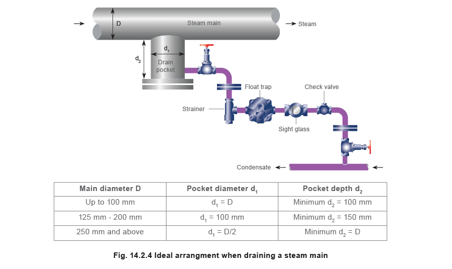
With steam mains drainage provided drain pockets are installed as recommended in Module 10.3 then drain line between pocket and steam trap may be horizontal If drain pocket is not as deep as recommendation then steam trap should be fitted equivalent distance below it (see Figure 14.2.4)
ท่อ discharge จากกับดัก
ท่อ discharge จากกับดัก
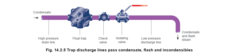
ท่อเหล่านี้จะ carry คอนเดนเสท, ก๊าซที่ไม่ condense, and flash steam จากกับดักไปยังระบบ return คอนเดนเสท (รูปที่ 14.2.5) Flash steam formed as คอนเดนเสท discharged from high-pressure space before steam trap to lower pressure space of ระบบ return คอนเดนเสท (Flash steam discussed briefly in Module 14.1 and in more detail in Module 2.2) ท่อเหล่านี้ should also fall in direction of flow to maintain free flow of คอนเดนเสท On shorter lines fall should be discernible by sight On longer lines fall should be about 1:70 that is 100 mm every 7 metres
Discharging into flooded return lines
Discharging into flooded return lines
Discharging traps into flooded return lines is not recommended especially with blast action traps (thermodynamic or inverted bucket types) which remove คอนเดนเสท at saturation temperature Good examples of flooded คอนเดนเสท mains are pumped return lines and rising คอนเดนเสท lines They often follow same route as steam lines and it is tempting to simply connect mains drainage steam trap discharge lines into them However high volume of flash steam released into long flooded lines will violently push water along pipe causing waterhammer noise and in time mechanical failure of pipe
ท่อ return ร่วม
ท่อ return ร่วม
Where คอนเดนเสท from more than one trap flows to same collecting point such as vented receiver it is usual to run common line into which individual trap discharge lines are connected Provided layouts as featured in Figures 14.2.6/7/8 and 10 are observed and pipework is adequately sized as indicated in Module 14.3 this is not a problem
กับดัก blast discharge
กับดัก blast discharge
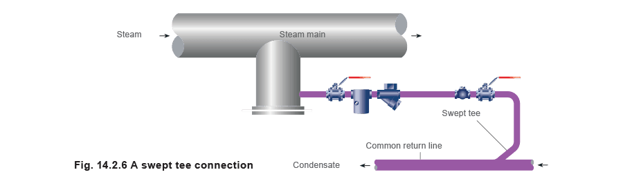
If blast discharge traps (thermodynamic or inverted bucket types) are used reactionary forces and velocities can be high Swept tees will help to reduce mechanical stress and erosion at point where discharge line joins common return line (see Figure 14.2.6)
กับดัก continuous discharge
กับดัก continuous discharge
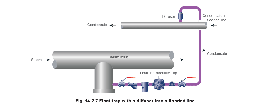
If for some reason swept tees cannot be used float-thermostatic trap with its continuous discharge action is better option (Figure 14.2.7) Flooded line will absorb dissipated energy from (relatively small) continuous flow from float-thermostatic trap more easily If pressure difference between steam and คอนเดนเสท mains is very high then diffuser will help to cushion discharge reducing both erosion and noise
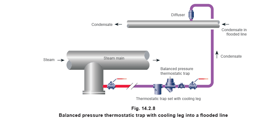
Another alternative is to use thermostatic trap that holds back คอนเดนเสท until it cools below steam saturation temperature; this reduces amount of flash steam formed (Figure 14.2.8)
To avoid waterlogging steam main use of generous collecting pocket on main plus cooling leg of 2 to 3 m of unlagged pipe to trap is essential Cooling leg stores คอนเดนเสท while it is cooling to discharge temperature If there is any danger of waterlogging steam main thermostatic traps should not be used
โรงงานควบคุมอุณหภูมิพร้อมกับดัก drain into flooded lines
โรงงานควบคุมอุณหภูมิพร้อมกับดัก drain into flooded lines
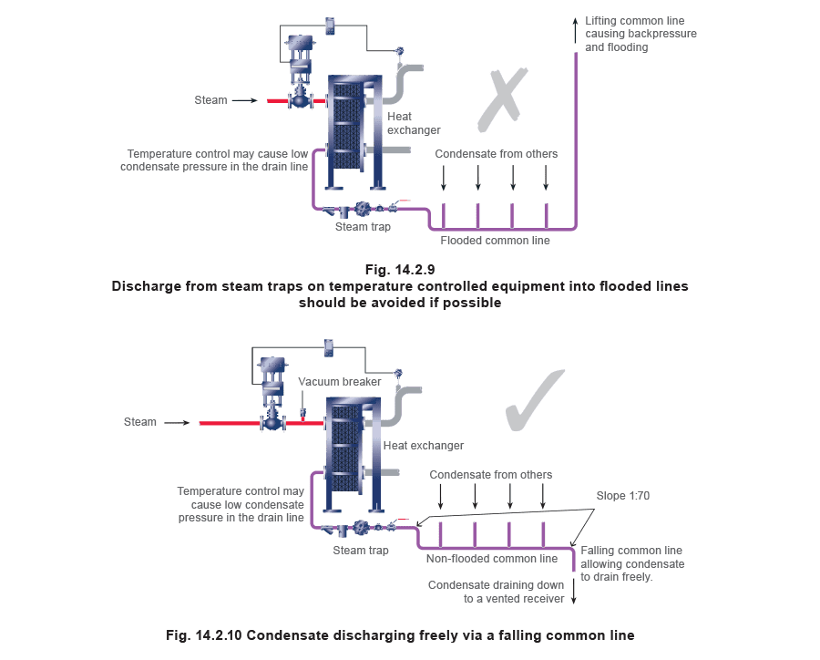
Processes using temperature control provide example where supply steam pressure is throttled across control valve Effect of this is to reduce steam trap capacity to point where คอนเดนเสท flow can stop completely and system is said to have stalled Subject of stall is discussed in greater depth in Block 13 Stall occurs as result of insufficient steam pressure to purge steam plant of คอนเดนเสท and is more likely when plant has high turndown from full-load to part load Not all temperature controlled systems will stall but backpressure caused by คอนเดนเสท system could have adverse effect on performance of trap This in turn might impair heat transfer capability of process (Figure 14.2.9) คอนเดนเสท drain lines should therefore be configured so that คอนเดนเสท cannot flood main into which they are draining as depicted in Figure 14.2.10
ท่อ discharge ที่แรงดันต่างกัน
ท่อ discharge ที่แรงดันต่างกัน
คอนเดนเสท from more than one temperature controlled process may join common line as long as this line is:
- Designed to slope in direction of flow to collection point
- Sized to cater for cumulative effects of any flash steam from each of branch lines at full-load Concept of connecting discharges from traps at different pressures is sometimes misunderstood If branch lines and common line are correctly sized pressures downstream of each trap will be virtually same However if these lines are undersized flow of คอนเดนเสท and flash steam will be restricted due to build up of backpressure caused by increased resistance to flow within pipe คอนเดนเสท flowing from traps draining lower pressure systems will tend to be more restricted Each part of discharge piping system should be sized to carry any flash steam present at acceptable steam velocities Discharge from high-pressure trap will not interfere with that from low-pressure trap if discharge lines and common line are properly sized and sloped in direction of flow Module 14.3 ‘Sizing of condensate return lines’ gives further details
ท่อ return แบบสูบ
ท่อ return แบบสูบ
Flash steam may at some point be separated from คอนเดนเสท and used in recovery system or simply vented to atmosphere from suitable receiver (Figure 14.2.11) Residual hot คอนเดนเสท from latter can be pumped on to suitable collecting tank such as boiler feedtank When pump is served from vented receiver pumped return line will be fully flooded with คอนเดนเสท at temperatures below 100°C which means flash steam is less likely to occur in line
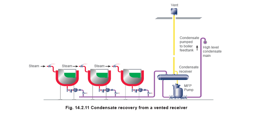
Flow in pumped return line is intermittent as pump starts and stops according to its needs Pump discharge rate will be higher than rate at which คอนเดนเสท enters pump It is therefore pump discharge rate which determines size of pump discharge line and not rate at which คอนเดนเสท enters pump
Pumping of คอนเดนเสท is discussed in further detail in Module 14.4 ‘Pumping condensate from vented receivers’