Loop Uap dan Kondensat
Bagaimana uap dihasilkan, didistribusikan, dikontrol dan digunakan? Bagaimana kondensat didaur ulang? Ikhtisar dasar tentang sistem uap.
Modul Loop Uap dan Kondensat ini dimaksudkan untuk memberikan ikhtisar singkat dan non-teknis tentang pabrik uap. Modul ini menawarkan penjelasan menyeluruh tentang bagaimana berbagai bagian pabrik uap saling berhubungan - dan merupakan bacaan yang berguna bagi siapa pun yang tidak terbiasa dengan topik ini, sebelum melanjutkan ke Blok berikutnya, atau, memang, sebelum melakukan bentuk studi mendalam apa pun tentang teori uap atau peralatan pabrik uap.
Rumah ketel
Rumah ketel
Ketel uap
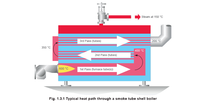
Ketel uap adalah jantung dari sistem uap. Ketel paket modern yang khas didukung oleh burner yang mengirimkan panas ke dalam tabung ketel.
Gas panas dari burner melewati bolak-balik hingga 3 kali melalui serangkaian tabung untuk mendapatkan transfer panas maksimum melalui permukaan tabung ke air ketel di sekitarnya. Setelah air mencapai suhu saturasi (suhu di mana air akan mendidih pada tekanan tersebut), gelembung uap diproduksi, yang naik ke permukaan air dan pecah. Uap dilepaskan ke ruang di atasnya, siap memasuki sistem uap. Katup stop atau crown mengisolasi ketel dan tekanan uapnya dari proses atau pabrik.
 Jika uap diberi tekanan, uap akan menempati ruang yang lebih kecil. Ketel uap biasanya dioperasikan di bawah tekanan, sehingga lebih banyak uap dapat diproduksi oleh ketel yang lebih kecil dan ditransfer ke titik penggunaan menggunakan perpipaan berdiameter kecil. Saat diperlukan, tekanan uap dikurangi pada titik penggunaan.
Selama jumlah uap yang diproduksi di dalam ketel sama besarnya dengan yang meninggalkan ketel, ketel akan tetap bertekanan. Burner akan beroperasi untuk mempertahankan tekanan yang benar. Ini juga mempertahankan suhu uap yang benar, karena tekanan dan suhu uap jenuh berhubungan langsung.
Ketel memiliki sejumlah perlengkapan dan kontrol untuk memastikan bahwa ia beroperasi secara aman, ekonomis, efisien dan pada tekanan yang konsisten.
Air umpan
Kualitas air yang dipasok ke dalam ketel penting. Air harus pada suhu yang benar, biasanya sekitar 80°C, untuk menghindari sengatan termal pada ketel, dan untuk menjaga agar tetap beroperasi secara efisien. Air juga harus memiliki kualitas yang benar untuk menghindari kerusakan pada ketel.
Air minum biasa yang tidak diolah tidak sepenuhnya cocok untuk ketel dan dapat dengan cepat menyebabkannya berbusa dan berkerak. Ketel menjadi kurang efisien dan uap menjadi kotor dan basah. Umur ketel juga akan berkurang.
Air harus diolah dengan bahan kimia untuk mengurangi kotoran yang dikandungnya.
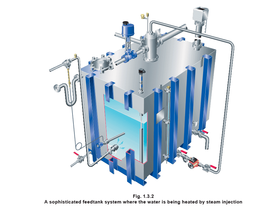
Baik pengolahan air umpan dan pemanasan terjadi di tangki umpan, yang biasanya terletak tinggi di atas ketel. Pompa umpan akan menambahkan air ke dalam ketel saat diperlukan. Memanaskan air di tangki umpan juga mengurangi jumlah oksigen terlarut di dalamnya. Ini penting, karena air yang mengandung oksigen bersifat korosif.
Jika uap diberi tekanan, uap akan menempati ruang yang lebih kecil. Ketel uap biasanya dioperasikan di bawah tekanan, sehingga lebih banyak uap dapat diproduksi oleh ketel yang lebih kecil dan ditransfer ke titik penggunaan menggunakan perpipaan berdiameter kecil. Saat diperlukan, tekanan uap dikurangi pada titik penggunaan.
Selama jumlah uap yang diproduksi di dalam ketel sama besarnya dengan yang meninggalkan ketel, ketel akan tetap bertekanan. Burner akan beroperasi untuk mempertahankan tekanan yang benar. Ini juga mempertahankan suhu uap yang benar, karena tekanan dan suhu uap jenuh berhubungan langsung.
Ketel memiliki sejumlah perlengkapan dan kontrol untuk memastikan bahwa ia beroperasi secara aman, ekonomis, efisien dan pada tekanan yang konsisten.
Air umpan
Kualitas air yang dipasok ke dalam ketel penting. Air harus pada suhu yang benar, biasanya sekitar 80°C, untuk menghindari sengatan termal pada ketel, dan untuk menjaga agar tetap beroperasi secara efisien. Air juga harus memiliki kualitas yang benar untuk menghindari kerusakan pada ketel.
Air minum biasa yang tidak diolah tidak sepenuhnya cocok untuk ketel dan dapat dengan cepat menyebabkannya berbusa dan berkerak. Ketel menjadi kurang efisien dan uap menjadi kotor dan basah. Umur ketel juga akan berkurang.
Air harus diolah dengan bahan kimia untuk mengurangi kotoran yang dikandungnya.
Baik pengolahan air umpan dan pemanasan terjadi di tangki umpan, yang biasanya terletak tinggi di atas ketel. Pompa umpan akan menambahkan air ke dalam ketel saat diperlukan. Memanaskan air di tangki umpan juga mengurangi jumlah oksigen terlarut di dalamnya. Ini penting, karena air yang mengandung oksigen bersifat korosif.
 Blowdown
Pengisian bahan kimia ke dalam air umpan ketel akan mengakibatkan keberadaan padatan tersuspensi di dalam ketel. Padatan ini pasti akan mengumpul di bagian bawah ketel dalam bentuk lumpur, dan dihilangkan melalui proses yang dikenal sebagai blowdown bawah. Ini dapat dilakukan secara manual - petugas ketel akan menggunakan kunci untuk membuka katup blowdown untuk jangka waktu tertentu, biasanya dua kali sehari.
Kotoran lainnya tetap berada di dalam air ketel setelah pengolahan dalam bentuk padatan terlarut. Konsentrasi mereka akan meningkat seiring dengan produksi uap oleh ketel dan akibatnya ketel perlu secara berkala dibersihkan sebagian isinya untuk mengurangi konsentrasi. Ini disebut kontrol total padatan terlarut (kontrol TDS). Proses ini dapat dilakukan oleh sistem otomatis yang menggunakan probe di dalam ketel, atau ruang sensor kecil yang berisi sampel air ketel, untuk mengukur level TDS dalam ketel. Setelah level TDS mencapai titik yang ditetapkan, pengontrol memberi sinyal pada katup blowdown untuk membuka untuk jangka waktu tertentu. Air yang hilang diganti oleh air umpan dengan konsentrasi TDS yang lebih rendah, akibatnya TDS keseluruhan ketel berkurang.
Kontrol level
Jika level air di dalam ketel tidak dikontrol dengan hati-hati, konsekuensinya bisa bencana. Jika level air turun terlalu rendah dan tabung ketel terekspos, tabung ketel bisa terlalu panas dan gagal, menyebabkan ledakan. Jika level air menjadi terlalu tinggi, air bisa memasuki sistem uap dan mengganggu proses.
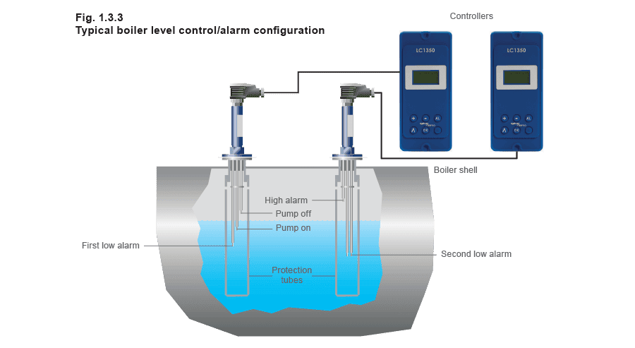
Untuk alasan ini, kontrol level otomatis digunakan. Untuk mematuhi peraturan, sistem kontrol level juga menggabungkan fungsi alarm yang akan beroperasi untuk mematikan ketel dan memperingatkan jika ada masalah dengan level air. Metode umum kontrol level adalah menggunakan probe yang mendeteksi level air dalam ketel. Pada level tertentu, pengontrol akan mengirimkan sinyal ke pompa umpan yang akan beroperasi untuk memulihkan level air, mati ketika level yang telah ditentukan tercapai. Probe akan menggabungkan level di mana pompa dinyalakan dan dimatikan, dan di mana alarm level rendah atau tinggi diaktifkan. Sistem alternatif menggunakan float.
Blowdown
Pengisian bahan kimia ke dalam air umpan ketel akan mengakibatkan keberadaan padatan tersuspensi di dalam ketel. Padatan ini pasti akan mengumpul di bagian bawah ketel dalam bentuk lumpur, dan dihilangkan melalui proses yang dikenal sebagai blowdown bawah. Ini dapat dilakukan secara manual - petugas ketel akan menggunakan kunci untuk membuka katup blowdown untuk jangka waktu tertentu, biasanya dua kali sehari.
Kotoran lainnya tetap berada di dalam air ketel setelah pengolahan dalam bentuk padatan terlarut. Konsentrasi mereka akan meningkat seiring dengan produksi uap oleh ketel dan akibatnya ketel perlu secara berkala dibersihkan sebagian isinya untuk mengurangi konsentrasi. Ini disebut kontrol total padatan terlarut (kontrol TDS). Proses ini dapat dilakukan oleh sistem otomatis yang menggunakan probe di dalam ketel, atau ruang sensor kecil yang berisi sampel air ketel, untuk mengukur level TDS dalam ketel. Setelah level TDS mencapai titik yang ditetapkan, pengontrol memberi sinyal pada katup blowdown untuk membuka untuk jangka waktu tertentu. Air yang hilang diganti oleh air umpan dengan konsentrasi TDS yang lebih rendah, akibatnya TDS keseluruhan ketel berkurang.
Kontrol level
Jika level air di dalam ketel tidak dikontrol dengan hati-hati, konsekuensinya bisa bencana. Jika level air turun terlalu rendah dan tabung ketel terekspos, tabung ketel bisa terlalu panas dan gagal, menyebabkan ledakan. Jika level air menjadi terlalu tinggi, air bisa memasuki sistem uap dan mengganggu proses.
Untuk alasan ini, kontrol level otomatis digunakan. Untuk mematuhi peraturan, sistem kontrol level juga menggabungkan fungsi alarm yang akan beroperasi untuk mematikan ketel dan memperingatkan jika ada masalah dengan level air. Metode umum kontrol level adalah menggunakan probe yang mendeteksi level air dalam ketel. Pada level tertentu, pengontrol akan mengirimkan sinyal ke pompa umpan yang akan beroperasi untuk memulihkan level air, mati ketika level yang telah ditentukan tercapai. Probe akan menggabungkan level di mana pompa dinyalakan dan dimatikan, dan di mana alarm level rendah atau tinggi diaktifkan. Sistem alternatif menggunakan float.
Aliran uap ke pabrik
Aliran uap ke pabrik
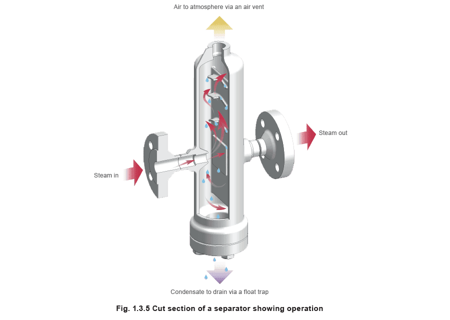
Ketika uap mengkondensasi, volumenya berkurang secara dramatis, yang mengakibatkan penurunan tekanan secara lokal. Penurunan tekanan ini melalui sistem menciptakan aliran uap melalui pipa. The steam generated in the boiler must be conveyed through the pipework to the point where its heat energy is required. Initially there will be one or more main pipes or steam mains which carry steam from the boiler in the general direction of the steam using plant. Smaller branch pipes can then distribute the steam to the individual pieces of equipment. Steam at high pressure occupies a lower volume than at atmospheric pressure. The higher the pressure, the smaller the bore of pipework required for distribution of a given mass of steam. Steam quality It is important to ensure that the steam leaving the boiler is delivered to the process in the right condition. To achieve this the pipework which carries the steam around the plant normally incorporates strainers, separators and steam traps. A strainer is a form of sieve in the pipeline. It contains a mesh through which the steam must pass. Any passing debris will be retained by the mesh. A strainer should regularly be cleaned to avoid blockage. Debris should be removed from the steam flow because it can be very damaging to plant, and may also contaminate the final product. The steam should be as dry as possible to ensure it is carrying heat effectively. A separator is a body in the pipeline which contains a series of plates or baffles which interrupt the path of the steam. The steam hits the plates, and any drops of moisture in the steam collect on them, before draining from the bottom of the separator. Steam passes from the boiler into the steam mains. Initially the pipework is cold and heat is transferred to it from the steam. The air surrounding the pipes is also cooler than the steam, so the pipework will begin to lose heat to the air. Insulation fitted around the pipe will reduce this heat loss considerably. When steam from the distribution system enters the steam using equipment the steam will again give up energy by: a) warming up the equipment and b) continuing to transfer heat to the process. As steam loses heat, it turns back into water. Inevitably the steam begins to do this as soon as it leaves the
boiler. The water which forms is known as condensate, which tends to run to the bottom of the pipe and is carried along with the steam flow. This must be removed from the lowest points in the distribution pipework for several reasons:
- Condensate does not transmit heat effectively. A film of condensate inside plant will reduce the efficiency with which heat is transferred.
- When air dissolves into condensate, it becomes corrosive.
- Accumulated condensate can cause noisy and damaging waterhammer.
- Inadequate drainage leads to leaking joints.

 A device known as a steam trap is used to release condensate from the pipework whilst preventing the steam from escaping from the system. It can do this in several ways:
 - A float trap uses the difference in density between steam and condensate to operate a valve. As condensate enters the trap, a float is raised and the float lever mechanism opens the main valve to allow condensate to drain. When the condensate flow reduces the float falls and closes the main valve, thus preventing the escape of steam
- Thermodynamic traps contain a disc which opens to condensate and closes to steam.
- In bimetallic thermostatic traps, a bimetallic element uses the difference in temperature between steam and condensate to operate the main valve.
- In balanced pressure thermostatic traps, a small liquid filled capsule which is sensitive to heat operates the valve. Once the steam has been employed in the process, the resulting condensate needs to be drained from the plant and returned to the boiler house. This process will be considered later in this Module. Pressure reduction As mentioned before, steam is usually generated at high pressure, and the pressure may have to be reduced at the point of use, either because of the pressure limitations of the plant, or the temperature limitations of the process. This is achieved using a pressure reducing valve.
Steam at the point of use
Steam at the point of use
A large variety of steam using plant exists. A few examples are described below:
- Jacketed pan - Large steel or copper pans used in the food and other industries to boil substances - anything from prawns to jam. These large pans are surrounded by a jacket filled with steam, which acts to heat up the contents.
- Autoclave - A steam-filled chamber used for sterilisation purposes, for example medical equipment, or to carry out chemical reactions at high temperatures and pressures, for example the curing of rubber.
- Heater battery - For space heating, steam is supplied to the coils in a heater battery. The air to be heated passes over the coils.
- Process tank heating - A steam filled coil in a tank of liquid used to heat the contents to the desired temperature.
- Vulcaniser - A large receptacle filled with steam and used to cure rubber.
- Corrugator - A series of steam heated rollers used in the corrugation process in the production of cardboard.
- Heat exchanger - For heating liquids for domestic/industrial use.
Control of the process
Any steam using plant will require some method to control the flow of steam. A constant flow of steam at the same pressure and temperature is often not what is required – a gradually increasing flow will be needed at start-up to gently warm the plant, and once the process reaches the desired temperature, the flow must be reduced.
Control valves are used to control the flow of steam. The actuator, see Figure 1.3.6, is the device that applies the force to open or close the valve. A sensor monitors conditions in the process, and transmits information to the controller. The controller compares the process condition with the set value and sends a corrective signal to the actuator, which adjusts the valve setting.
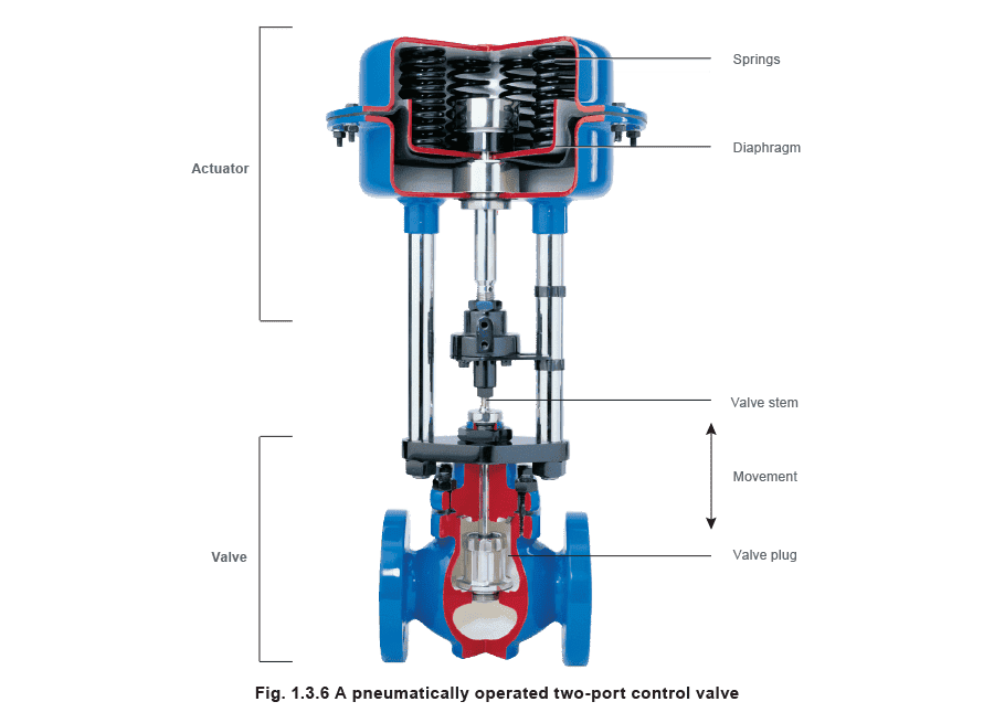
A variety of control types exist:
- Pneumatically actuated valves - Compressed air is applied to a diaphragm in the actuator to open or close the valve.
- Electrically actuated valves - An electric motor actuates the valve.
- Self-acting - There is no controller as such - the sensor has a liquid fill which expands and contracts in response to a change in process temperature. This action applies force to open or close the valve.
Condensate removal from plant
Condensate removal from plant
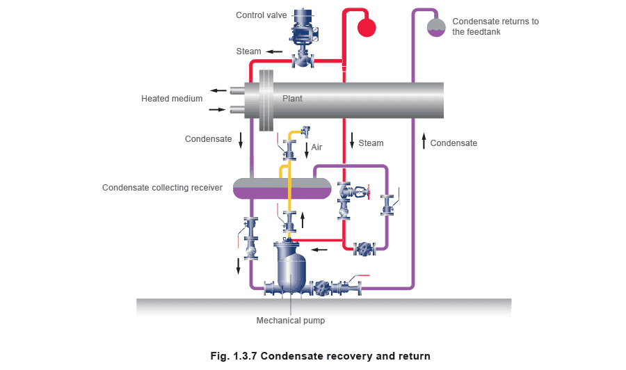
Often, the condensate which forms will drain easily out of the plant through a steam trap. The condensate enters the condensate drainage system. If it is contaminated, it will probably be sent to drain. If not, the valuable heat energy it contains can be retained by returning it to the boiler feedtank. This also saves on water and water treatment costs. Sometimes a vacuum may form inside the steam using plant. This hinders condensate drainage, but proper drainage from the steam space maintains the effectiveness of the plant. The condensate may then have to be pumped out. Mechanical (steam powered) pumps are used for this purpose. These, or electric powered pumps, are used to lift the condensate back to the boiler feedtank.
A mechanical pump, see Figure 1.3.7, is shown draining an item of plant. As can be seen, the steam and condensate system represents a continuous loop.
Once the condensate reaches the feedtank, it becomes available to the boiler for recycling.
 Energy monitoring
****In today’s energy conscious environment, it is common for customers to monitor the energy consumption of their plant.
Steam flowmeters are used to monitor the consumption of steam, and used to allocate costs to individual departments or items of plant.
Energy monitoring
****In today’s energy conscious environment, it is common for customers to monitor the energy consumption of their plant.
Steam flowmeters are used to monitor the consumption of steam, and used to allocate costs to individual departments or items of plant.