Hubungan Beban Panas, Penukar Panas dan Beban Uap
Perhitungan untuk aplikasi penukaran panas termasuk beban desain dan persyaratan tekanan/laju aliran uap
Uap jenuh digunakan untuk menyediakan panas primer ke fluida proses dalam penukar panas. Istilah penukar panas digunakan untuk menggambarkan semua jenis peralatan di mana perpindahan panas dipromosikan dari satu fluida ke fluida lain. Untuk kemudahan, definisi luas ini akan diterapkan pada istilah penukar panas. Meskipun penukar panas shell dan tube serta penukar panas plat akan terutama dirujuk, stall juga mungkin relevan dengan aplikasi termasuk baterai pemanas udara, koil tangki terendam, bejana berjaket, dan kalorifier penyimpanan.
Aplikasi kontrol suhu
Dalam aplikasi kontrol suhu, suhu masuk fluida sekunder ke penukar panas mungkin berubah seiring waktu. Ini berarti bahwa untuk mempertahankan suhu keluar fluida sekunder yang konsisten, panas yang disuplai ke penukar panas juga harus bervariasi. Ini dapat dicapai dengan menggunakan katup kontrol di saluran masuk sisi primer penukar panas, seperti yang ditunjukkan pada Gambar 13.2.1..
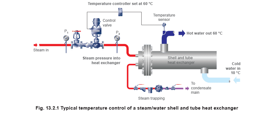 Katup kontrol digunakan untuk mengubah laju aliran dan tekanan uap sehingga panas yang masuk ke penukar panas dapat dikontrol. Memodulasi posisi katup kontrol kemudian mengontrol suhu keluar fluida sekunder. Sensor pada keluar fluida sekunder memantau suhunya, dan memberikan sinyal untuk pengontrol. Pengontrol membandingkan suhu aktual dengan suhu setel, dan sebagai hasilnya, memberi sinyal aktuator untuk menyesuaikan posisi katup kontrol.
For a constant heating area and heat transfer coefficient, the rate at which heat is transferred from the steam to the secondary fluid for a particular heat exchanger is determined by the mean temperature difference between the two fluids. A larger difference in mean temperatures will create a large heat transfer rate and vice versa. On partially closing the control valve, the steam pressure and the temperature difference fall. Conversely, if the control valve is opened so that the steam mass flow and hence pressure in the heat exchanger rise, the mean temperature difference between the two fluids increases.
Altering the steam pressure will also slightly affect the amount of heat energy available in the condensing steam as the enthalpy of evaporation actually falls with increasing pressure. This means that the latent heat available per kg of steam reduces as the steam pressure increases. If steam flow accuracy is required, this must be accounted for. Example 13.2.1 A manufacturer is to design a heat exchanger in which the specification calls for steam at 4 bar g to heat secondary water from 10°C to 60°C. The water flow is to be constant at all loads at 1.5 L/s. It is assumed that 1 litre of water has a mass of 1 kg, so the mass flowrate = 1.5 L/s x 1 kg/L = 1.5 kg/s.
The manufacturer uses a heat transfer coefficient ‘U’ for the heat exchanger of 2 500 W/m² °C. Take the specific heat of water as 4.19 kJ/kg °C. Determine: (A) The design heat load.
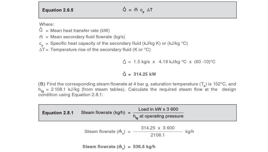
(B) The corresponding steam flowrate.
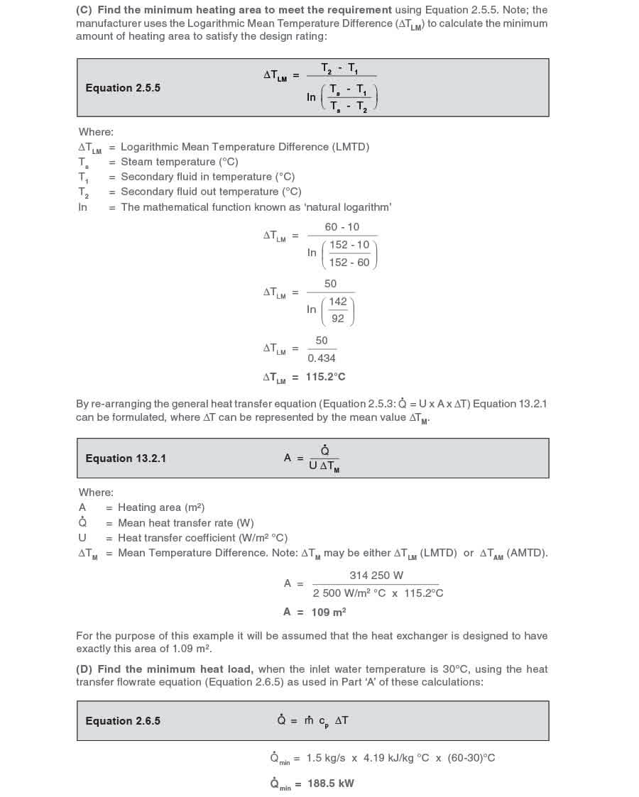
(C) The minimum heating area required.
Also, if the customer’s minimum heat load occurs when the inlet water temperature rises to 30°C, determine:
(D) The minimum heat load.
(E) The corresponding steam pressure in the heat exchanger.
(F) The corresponding steam flowrate.
Calculations:
(A) Find the design heat load using the heat transfer flowrate equation (Equation 2.6.5):
 To calculate the corresponding steam flowrate, it is first necessary to determine the steam temperature at the minimum load condition.
It is possible to use the ΔTLM design figures to accurately predict the steam temperature for any load condition, but this requires the use of logarithmic calculations. However, once the exchanger
To calculate the corresponding steam flowrate, it is first necessary to determine the steam temperature at the minimum load condition.
It is possible to use the ΔTLM design figures to accurately predict the steam temperature for any load condition, but this requires the use of logarithmic calculations. However, once the exchanger
size is fixed and the design temperatures are known, it is much easier to predict operating temperatures using what could be termed a heat exchanger Temperature Design Constant (TDC).
The TDC method does not require logarithmic calculations. Please note: TDC cannot be used on those applications where the secondary flowrate varies or where control is achieved by varying the condensate level in the steam space. Note: When sizing a heat exchanger it is normal for heat exchanger manufacturers to use the ΔTLM method. Once sized, by knowing the heating area and the full-load operating temperatures, TDC can be used to accurately predict all operating temperatures resulting from changes in load, as can be seen in the following text. Operating temperatures can also be predicted graphically by using what is termed a ‘Stall Chart’. This method is discussed in Modules 13.5, 13.6, and 13.7. Temperature Design Constant (TDC) For any type of steam-heated exchanger with the secondary liquid flowing at a constant rate, TDC can be calculated from the test figures quoted by the manufacturer for full-load. If these data sets are not available and the heat exchanger is already installed in service, TDC can be calculated by observing the steam pressure (and finding the steam temperature from steam tables) and the corresponding secondary inlet and outlet temperatures at any load.
TDC is the ratio of the steam to water temperatures at the inlet and outlet; and is shown in Equation 13.2.2.
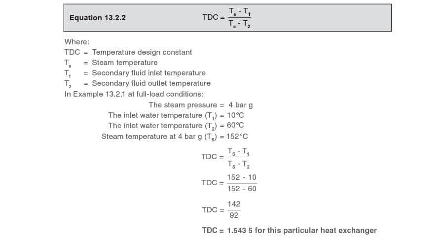 The TDC equation can be transposed to find any one variable as long as the other three variables are known. The following equations are derived from the TDC equation (Equation 13.2.2).
To find the steam temperature at any load use Equation 13.2.3:
 To find the secondary fluid inlet temperature at any load use Equation 13.2.4:
 To find the secondary fluid outlet temperature at any load use Equation 13.2.5:
 For any heat exchanger with a constant secondary flowrate, the operating steam temperature can be calculated for any combination of inlet temperature and outlet temperature.
In Example 13.2.1 the secondary outlet temperature remains at 60°C, and minimum load occurs when the inlet temperature is 30°C. What is the steam temperature at minimum load?
Inlet temperature = 30°C
Outlet temperature = 60°C
 (E) Find the corresponding heat exchanger steam pressure and enthalpy at minimum load
From steam tables:
A steam temperature of 115.2°C corresponds with a steam pressure of 0.7 bar g.
The specific enthalpy of evaporation at 0.7 bar g (hfg) = 2 215 kJ/kg
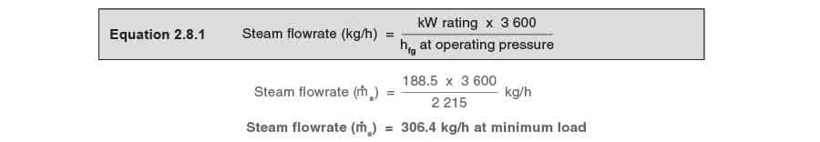
(F) Find the steam flowrate at minimum load:
From (D) the minimum heat load is 188.5 kW.
From (E) the hfg is 2 215 kJ/kg.
Using Equation 2.8.1: