FT44 Bẫy hơi phao cầu bằng thép carbon

FT44

FT44 Bẫy hơi phao cầu bằng thép carbon

FT44 là bẫy hơi phao cầu nối bích bằng thép carbon, có các chi tiết bên trong bằng thép không gỉ, bộ xả khí tự động và khả năng bảo trì tại chỗ, dùng cho các dịch vụ hơi và nước ngưng đã được lập tài liệu trong dải DN15-DN50 và DN80-DN100.

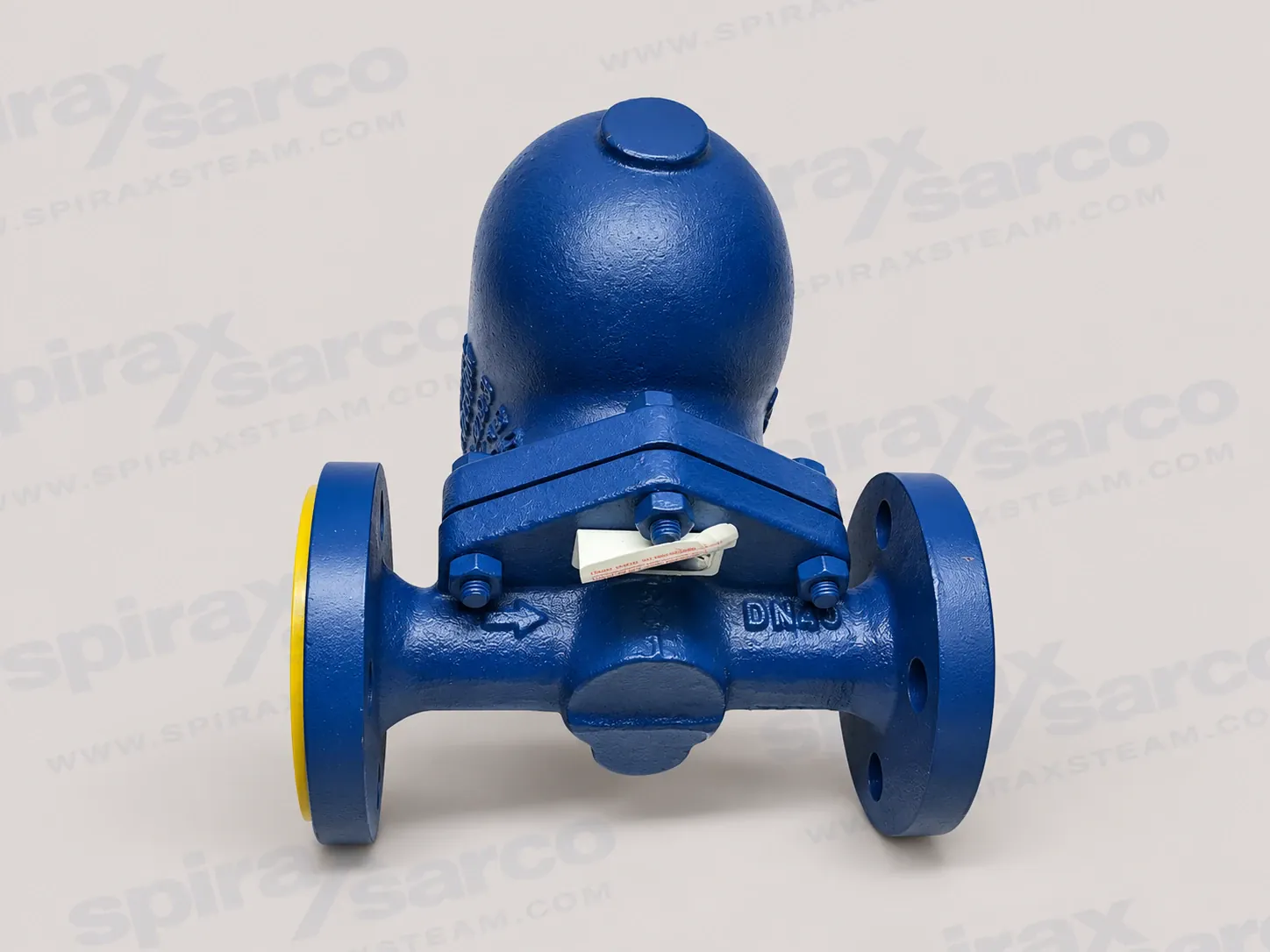
Spirax Sarco FT44 bẫy hơi phao cầu bằng thép carbon

Spirax Sarco FT44 là bẫy hơi phao cầu nối bích bằng thép carbon, dùng để xả nước ngưng khỏi hệ thống hơi và giữ hơi trong các điều kiện vận hành đã được lập tài liệu. Sản phẩm kết hợp thân và nắp bằng thép carbon với các chi tiết bên trong bằng thép không gỉ và bộ xả khí tự động. Van chính do phao điều khiển xả nước ngưng liên tục theo mức chất lỏng, còn bộ xả khí hỗ trợ loại bỏ không khí trong lúc khởi động. FT44 là lựa chọn thực tế cho hệ thống thoát nước hơi cần xả nước ngưng tin cậy, kết nối mặt bích và bảo trì tại chỗ.

Trang FT44 bao phủ một nhận dạng sản phẩm trong các dải kích thước đã được lập tài liệu DN15 to DN50 và DN80 to DN100. Hai nhóm kích thước có các tờ dữ liệu kỹ thuật khác nhau và phải được kiểm tra riêng. Dải nhỏ có các cấp chênh áp FT44-4.5, FT44-10, FT44-14, FT44-21 và FT44-32; FT44-14 chỉ áp dụng cho các kích thước nhỏ. Dải DN80 và DN100 được lập tài liệu với FT44-4.5, FT44-10, FT44-21 và FT44-32. Cấp áp suất là một phần của lựa chọn, không phải hậu tố có thể thay đổi và thêm sau khi đặt hàng.

Để hiểu rộng hơn về việc xả nước ngưng, hướng dẫn lựa chọn bẫy hơi cung cấp bối cảnh ở cấp hệ thống. Phần giới thiệu sản phẩm này tập trung vào kết cấu FT44, phạm vi vận hành, bố trí lắp đặt và các kiểm tra đặt hàng cần thiết cho yêu cầu một model.

Nguyên lý hoạt động của bẫy hơi phao cầu FT44

Nước ngưng đi vào bẫy làm phao nổi lên và mở van chính theo mức chất lỏng. Khi nước ngưng được xả, phao hạ xuống và van đóng lại nhờ chênh áp sẵn có. Cơ cấu phao cầu phù hợp với việc xả liên tục vì van chính phản ứng với sự hiện diện của nước ngưng thay vì chờ một khoảng thời gian cố định. Bộ xả khí tự động tích hợp tạo một đường riêng cho không khí và các khí không ngưng khác trong lúc khởi động, giúp khoang hơi đạt điều kiện vận hành mà không coi không khí tích tụ như nước ngưng.

FT44 sử dụng capsule BP99/32 cho dịch vụ hơi quá nhiệt. Khả năng quá nhiệt theo tài liệu là 150 deg C tại 0 bar g và 50 deg C tại 32 bar g. Các giá trị này là điều kiện vận hành của capsule và phải được xem xét cùng biểu đồ áp suất-nhiệt độ của bẫy, không được coi là mức cho phép quá nhiệt chung ở mọi áp suất. Trước khi chọn bẫy, cần xem xét môi chất, áp suất và nhiệt độ hệ thống cũng như hậu quả của sự cố.

Bộ xả khí tự động và cơ cấu phao có các chức năng khác nhau. Bộ xả xử lý không khí khi khởi động, còn phao và van chính xử lý nước ngưng trong quá trình vận hành. Cụm này hữu ích cho việc thoát nước đường hơi chính và thiết bị công nghệ, nơi cần quan tâm đến khởi động nguội, loại bỏ không khí và xả nước ngưng liên tục. Sản phẩm không thay thế van an toàn, van giảm áp hoặc van điều khiển; hệ thống hơi xung quanh vẫn cần các biện pháp cô lập, bảo vệ và thoát nước riêng.

Thân thép carbon và các chi tiết bên trong có thể bảo trì

Thân và nắp FT44 bằng thép carbon, trong khi van chính, liên kết phao, bộ xả khí, giá đỡ và các vách ngăn bên trong sử dụng chi tiết bằng thép không gỉ theo kích thước và kiểu kết nối được chỉ định. Sự kết hợp này tạo ra ranh giới áp suất mặt bích chắc chắn và các chi tiết làm việc chống ăn mòn. Bảng vật liệu đầy đủ, gồm gioăng và các chi tiết nhả khóa hơi, được giữ trong phần thông tin kỹ thuật bên dưới để đối chiếu hồ sơ mua hàng và bảo trì với cấu hình được cung cấp.

Bẫy được thiết kế để bảo trì mà không làm ảnh hưởng đường ống khi có đủ biện pháp cô lập và không gian tiếp cận. Điều này hữu ích khi bẫy nối bích được lắp trên đường hơi chính cố định hoặc đường công nghệ và việc tháo toàn bộ thân sẽ gây thời gian dừng không cần thiết. Công việc vẫn yêu cầu cô lập, xả áp an toàn và làm nguội đường ống, đồng thời phải do người có năng lực thực hiện theo hướng dẫn lắp đặt và bảo trì. Khả năng bảo trì tại chỗ giảm ảnh hưởng đến đường ống nhưng không loại bỏ yêu cầu kiểm soát áp suất và nhiệt độ.

Tùy chọn van kim điều chỉnh bằng tay được ký hiệu FT44-C. Tùy chọn này bổ sung chức năng nhả khóa hơi cho bố trí FT44 nằm ngang và phải được nêu khi đặt hàng. FT44V là tùy chọn lắp đặt đứng, chỉ cho phép dòng chảy đi xuống. Các biến thể có tài liệu này giúp phù hợp với bố trí nhưng không thay đổi nhận dạng trang hoặc biến trang thành catalogue không giới hạn cho mọi sản phẩm thuộc họ FT.

Khi vật liệu là yếu tố quyết định, có thể xem xét tùy chọn phao cầu nối bích bằng gang qua trang bẫy hơi phao cầu FT43. Liên kết này là hướng lựa chọn vật liệu, không có nghĩa FT43 nằm trong thông số FT44. Nếu cần thân bằng thép không gỉ, có thể chuyển sang trang bẫy hơi phao cầu FTGS14 để đánh giá sản phẩm riêng.

Kích thước, tiêu chuẩn mặt bích và hướng dòng chảy

FT44 DN15, DN20, DN25, DN40 và DN50 được lập tài liệu với các kết nối mặt bích tích hợp. EN 1092 PN40 là kiểu mặt bích tiêu chuẩn, với kích thước face-to-face liên quan đến EN 26554 Series 1. Các tùy chọn ASME B16.5 Class 150, Class 300 và JIS/KS 20 có sẵn như các lựa chọn thay thế có tài liệu. Khi cần mặt bích không tiêu chuẩn, phải ghi lại cấp mặt bích, kích thước face-to-face và chi tiết bu lông trong yêu cầu thay vì suy đoán từ kích thước danh nghĩa.

DN80 và DN100 cũng là loại nối bích, với các kiểu EN 1092 PN40, EN 1759-1, ASME Class 150/300 và JIS/KS 20 tùy cấu hình được chọn. Tờ kỹ thuật DN80-DN100 chỉ quy định lắp đặt nằm ngang. FT44 tiêu chuẩn DN15-DN50 có thể lắp nằm ngang; FT44V là tùy chọn dòng chảy đứng xuống khi bố trí yêu cầu. Luôn sử dụng mũi tên trên thân để xác định hướng dòng chảy thực tế.

Đối với nhu cầu bẫy phao cầu nối ren kích thước nhỏ nằm ngoài phạm vi mặt bích FT44, trang bẫy hơi phao cầu FT14 cung cấp một hướng lựa chọn riêng. Không nên coi đây là bộ chuyển đổi hoặc sản phẩm thay thế kiểu mặt bích FT44. Tách riêng các họ kết nối giúp tránh đặt đúng model nhưng có bố trí đường ống không tương thích.

Giới hạn áp suất và nhiệt độ

Đối với DN15-DN50, điều kiện thiết kế thân là PN40. Áp suất cho phép tối đa là 40 bar g tại 100 deg C. Áp suất vận hành tối đa với hơi bão hòa là 32 bar g tại 239 deg C, còn nhiệt độ vận hành tối đa là 285 deg C tại 28.5 bar g. Nhiệt độ cho phép tối thiểu là -10 deg C và nhiệt độ vận hành tối thiểu là 0 deg C; vận hành ở nhiệt độ thấp hơn cần tham khảo. DN40 và DN50 bị giới hạn ở áp suất vận hành tối đa bằng chênh áp tối đa đã chọn.

Nhóm kích thước nhỏ có các mức chênh áp tối đa 4.5, 10, 14, 21 và 32 bar. FT44-14 được lập tài liệu cho DN15, DN20 và DN25, không cung cấp cho DN40 hoặc DN50. Không được để bẫy đang vận hành chịu áp suất lớn hơn 48 bar vì cơ cấu bên trong có thể hư hỏng. Áp suất thử thủy lực nguội thiết kế là 60 bar g, nhưng phép thử khi đã lắp chi tiết bên trong phải nằm trong giới hạn chênh áp áp dụng.

Đối với DN80-DN100, điều kiện thiết kế thân vẫn là PN40 và áp suất cho phép tối đa là 40 bar g tại 100 deg C. Áp suất vận hành tối đa là 32 bar g tại 239 deg C, với nhiệt độ vận hành tối đa 300 deg C tại 27.5 bar g. Các tùy chọn chênh áp có tài liệu là 4.5, 10, 21 và 32 bar. Không có cấu hình FT44-14 cho dải kích thước này. Phải kiểm tra giới hạn nhiệt độ thấp và điều kiện thử thủy lực nguội 60 bar g từ tờ DN80-DN100, không tự động chuyển từ bảng dải nhỏ.

Biểu đồ áp suất-nhiệt độ xác định các vùng cấm và giới hạn theo từng mặt bích. Biểu đồ quan trọng khi hệ thống làm việc gần đường cong hơi bão hòa, khi chọn kết nối Class 150 hoặc JIS/KS, hoặc khi quy trình sử dụng hơi quá nhiệt. Áp suất, nhiệt độ, chênh áp và áp suất ngược phía hạ lưu tác động lẫn nhau; một giá trị áp suất trên nhãn không đủ để xác định tính phù hợp.

Ứng dụng và tích hợp hệ thống

FT44 phù hợp với việc thoát nước đường hơi chính, thoát nước thiết bị công nghệ và các dịch vụ nước ngưng khác nằm trong giới hạn áp suất-nhiệt độ và chênh áp đã được lập tài liệu. Hoạt động phao liên tục có thể hữu ích khi tải nước ngưng thay đổi lúc khởi động hoặc trong sản xuất bình thường. Bộ xả khí tự động cũng phù hợp với hệ thống mà việc loại bỏ không khí ảnh hưởng đến quá trình gia nhiệt. Đánh giá ứng dụng cần gồm tải nước ngưng, tải khởi động, áp suất và nhiệt độ hơi, chênh áp sẵn có và áp suất đường hồi tại cửa ra của bẫy.

Khi khởi động, bộ xả khí tạo thêm lưu lượng xả nước lạnh trong lúc bẫy nóng lên. Dữ liệu khởi động FT44 cho các giá trị xả bổ sung tối thiểu khác nhau đối với DN15-DN25, DN40-DN50 và DN80-DN100, đồng thời phân biệt bẫy có cấp đến 21 bar với loại cấp 32 bar. Hệ thống khởi động nguội thường xuyên, làm việc gián đoạn hoặc có tải nước ngưng ban đầu lớn nên dùng các bảng này khi kiểm tra bố trí thoát nước. Các giá trị mô tả lượng nước lạnh xả thêm từ chức năng xả khí và không thay thế tính toán công suất đầy đủ.

Trong hệ thống hồi nước ngưng kín, hãy cân nhắc van một chiều phía hạ lưu khi có thể xảy ra dòng chảy ngược hoặc áp suất ngược. Áp suất ngược phải nằm trong giới hạn sản phẩm vì áp suất hạ lưu quá lớn có thể khiến van chính không mở hoặc đóng đúng. Với xả ra khí quyển, kết thúc đường ra ở vị trí an toàn và tính đến nước ngưng nóng, bắn tóe, tiếng ồn và khả năng cần bộ khuếch tán. Có thể dùng kính quan sát hoặc hệ thống theo dõi bẫy khi cần kiểm tra điều kiện vận hành mà không làm ảnh hưởng bẫy.

Kiểm tra lắp đặt, bảo trì và đặt hàng

Lắp FT44 với mũi tên trên thân theo hướng dòng chảy và giữ tay đòn phao nằm trong mặt phẳng ngang để phao chuyển động tự do. Khi bố trí đường ống yêu cầu, nên có một đoạn ống rơi nhỏ trước bẫy và đặt bẫy gần điểm thoát nước. Bố trí cô lập phía thượng lưu và hạ lưu, đủ không gian tháo nắp và cơ cấu, đồng thời đỡ độc lập đường ống nối để tải bên ngoài không truyền vào bẫy.

Trước khi bảo trì, cô lập các kết nối hơi và nước ngưng, xả áp an toàn ra khí quyển, để thân nguội và xác nhận khu vực làm việc an toàn. Hướng dẫn quy định các bố trí bảo trì riêng cho DN15-DN50 và DN80-DN100. Cụm van chính, cụm xả khí, gioăng, chi tiết phao/cần gạt và bộ chống xói mòn DN40-DN50 phải được đặt theo đúng kích thước, cấp áp suất và hướng nằm ngang hoặc đứng. Mô-men siết khuyến nghị là một phần của quy trình bảo dưỡng và phải lấy từ bảng áp dụng.

Yêu cầu đối với Spirax Sarco FT44 phải nêu kích thước danh nghĩa, cấp áp suất FT44, hướng nằm ngang hoặc đứng FT44V, tiêu chuẩn mặt bích, áp suất và nhiệt độ vận hành, tải nước ngưng, áp suất ngược dự kiến, chế độ khởi động và tùy chọn FT44-C hoặc nắp khoan. Cũng phải nêu yêu cầu chứng nhận hoặc kiểm tra khi đặt hàng. Khi lựa chọn bẫy hơi Spirax Sarco FT44, giữ các dữ liệu vận hành này cùng mã model giúp kiểm tra cấu hình cuối theo tài liệu đúng dải kích thước.

Vì vậy nên chọn Spirax Sarco FT44 theo một trường hợp vận hành đầy đủ thay vì chỉ theo số model. Các phần thông tin kỹ thuật và lắp đặt tiếp theo giữ lại kích thước chi tiết, giới hạn áp suất, dữ liệu xả khi khởi động, điều kiện an toàn, trình tự bảo trì và giới hạn phụ tùng cần thiết cho việc đánh giá.

Mô tả sản phẩm

FT44 là bẫy hơi phao cầu bằng thép carbon với chi tiết bên trong bằng thép không gỉ và bộ xả khí tự động. Có thể bảo trì bẫy mà không làm ảnh hưởng đường ống.

Các bố trí FT44 tiêu chuẩn là nằm ngang. FT44V là tùy chọn lắp đặt đứng và dòng chảy phải hướng xuống. FT44-C là tùy chọn van kim điều chỉnh bằng tay và nhả khóa hơi cho bố trí FT44 nằm ngang.

Hơi quá nhiệt

Capsule BP99/32 phù hợp với độ quá nhiệt 150 deg C tại 0 bar g và 50 deg C tại 32 bar g. Phải kiểm tra đồng thời giới hạn áp suất-nhiệt độ và áp suất vận hành thực tế.

Kết nối

DN15-DN50 sử dụng mặt bích EN 1092 PN40 với kích thước face-to-face theo EN 26554 Series 1. Các tùy chọn ASME B16.5 Class 150 và 300 cùng JIS/KS 20 có sẵn như các lựa chọn thay thế được lập tài liệu.

Chứng nhận

Sản phẩm đáp ứng các yêu cầu về thiết bị chịu áp suất đã nêu. Có thể cung cấp chứng chỉ EN 10204 3.1 khi yêu cầu lúc đặt hàng.
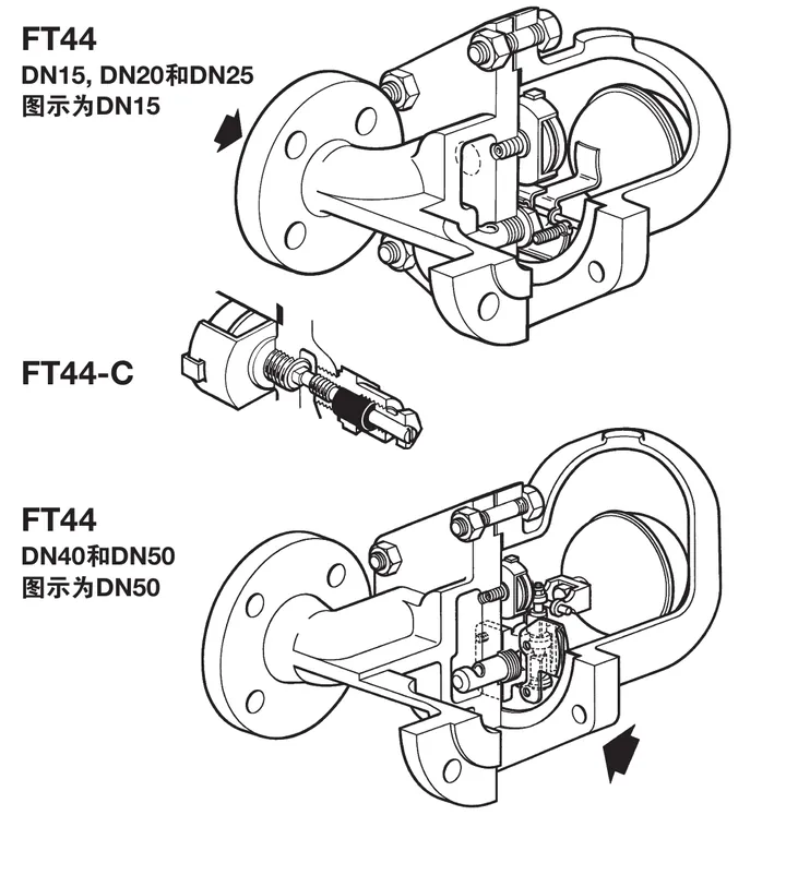
FT44 carbon steel ball float steam trap cutaway showing the float and stainless steel working internals
FT44 construction: DN15-DN25 and DN40-DN50 cutaway arrangements. The FT44-C option is shown for reference.

DN15-DN50 pressure and temperature limits
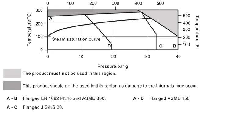
FT44 DN15-DN50 pressure and temperature limits graph with saturated steam curve and flange boundaries
DN15-DN50 pressure-temperature graph. The shaded regions are prohibited or may damage internal components.
ItemLimit
Body design conditionPN40
PMA40 bar g at 100 deg C
TMA300 deg C at 27.5 bar g
Minimum allowable temperature-10 deg C
PMO saturated steam32 bar g at 239 deg C
TMO285 deg C at 28.5 bar g
Minimum operating temperature0 deg C
Cold hydraulic test60 bar g maximum designed pressure
Complete operational trapDo not exceed 48 bar

DN40 and DN50 traps are limited to a PMO equal to DPMX. With internals fitted, a test pressure must not exceed the applicable DPMX.

Maximum differential pressure designationDN15, DN20, DN25DN40, DN50
FT44-4.54.5 bar4.5 bar
FT44-1010 bar10 bar
FT44-1414 barNot available
FT44-2121 bar21 bar
FT44-3232 bar32 bar

DN15-DN50 materials

No.PartMaterial
1BodyCarbon steel 1.0619+N / WCB
2Cover bolts and nutsSteel
3Cover gasketReinforced graphite sheet
4CoverCarbon steel 1.0619+N / WCB
5Valve seat and main valve assemblyStainless steel; arrangement depends on size and orientation
6Valve-seat and main-valve gasketsStainless steel or reinforced graphite sheet
7Main valve assembly hardwareStainless steel
8Float and lever mechanismStainless steel BS 1449 304 S16
9Air vent assemblyStainless steel
10-12Steam-lock-release optionStainless steel, steel and graphite as specified
13-15Supports, pivot support and pivot pinStainless steel
16Internal baffle for DN40 and DN50Stainless steel
17Air-vent-seat gasketStainless steel
18Erosion deflectorStainless steel

DN15-DN50 dimensions and approximate weights

SizePN40 AASME 300 AASME 150 AJIS/KS 20 ABCDEFWeight
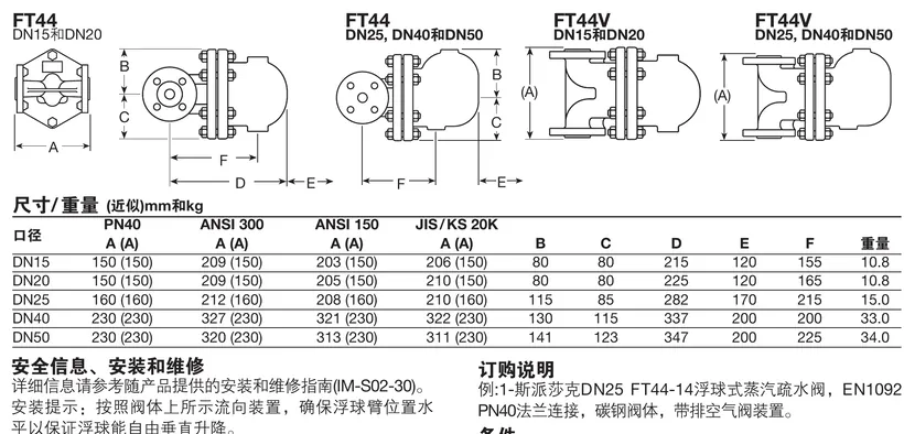
DN15150 (150)209 (150)203 (150)206 (150)808021512015510.8 kg
DN20150 (150)209 (150)205 (150)210 (150)808022512016510.8 kg
DN25160 (160)212 (160)208 (160)210 (160)1158528217021515.0 kg
DN40230 (230)327 (230)321 (230)322 (230)13011533720020033.0 kg
DN50230 (230)320 (230)313 (230)311 (230)14112334720022534.0 kg
FT44 and FT44V flange dimension diagrams with DN15 to DN50 dimensions and weights
FT44 and FT44V dimensional arrangements. Values in the table are approximate millimetres and kilograms.

For horizontal FT44 traps, flow is left to right for DN15-DN25 and right to left for DN40-DN50 when facing the body. FT44V flow is vertically downwards only.

DN80-DN100 technical data

DN80 and DN100 FT44 traps are flanged and are available for horizontal installation. The standard and optional flange arrangements are EN 1092 PN40, EN 1759-1, ASME Class 150/300 and JIS/KS 20 as applicable to the selected configuration.

ItemLimit or value
Body design conditionPN40
PMA40 bar g at 100 deg C
TMA300 deg C
Minimum allowable temperature-10 deg C
PMO saturated steam32 bar g at 239 deg C
TMO300 deg C at 27.5 bar g
Minimum operating temperature-10 deg C; consult for low-temperature applications
Cold hydraulic test60 bar g; with internals fitted, do not exceed 48 bar g
Differential pressure designationMaximum differential pressure
FT44-4.54.5 bar
FT44-1010 bar
FT44-2121 bar
FT44-3232 bar

DN80-DN100 materials and dimensions

PartMaterial
BodyCast steel 1.0619+N / WCB
CoverSteel 1.0619+N / WCB
Cover gasketReinforced graphite sheet
Main valve assembly and hardwareStainless steel and specified reinforced graphite gasket
Float and lever mechanismStainless steel
Air vent assembly and seat gasketStainless steel
SizeANSI 150 AANSI 300 APN40 AJIS/KS 20K ABCDEFWeight
DN8034336235335014012339020031095 kg
DN10035036635035014012339020031097 kg

Install DN80 and DN100 FT44 traps according to the body flow arrow and keep the float arm horizontal so the float can rise and fall freely.

Start-up additional cold-water discharge

When cold condensate is discharged during start-up, the thermostatic air-vent function can provide additional discharge. The table gives the minimum additional cold-water discharge in kg/h for the FT44 size groups. Use the row for the applicable pressure designation and combine it with the normal condensate load calculation.

Size and duty0.5 bar1 bar2 bar3 bar4.5 bar7 bar10 bar14 bar21 bar32 bar
DN15, DN20; up to 21 bar4506007801,0401,1401,3501,5301,7502,300-
DN15, DN20; 32 bar only1702503805206007808601,1401,1701,200
DN25; up to 21 bar4606809001,0801,3001,6001,9802,0502,600-
DN25; 32 bar only901203504606008509001,0201,2001,300
DN40, DN50; up to 21 bar4606809001,0801,3001,6001,9802,0502,600-
DN40, DN50; 32 bar only901203504606008509001,0201,2001,300
DN80, DN100; up to 21 bar9201,3601,8002,1602,6003,2002,9604,1005,200-
DN80, DN100; 32 bar only1802407009201,2001,7001,8002,0402,4002,600

The source values are minimum additional cold-water discharge in kg/h at the stated differential pressure. They are not a replacement for the FT44 normal condensate capacity review.

Ordering information

State the FT44 model designation, nominal size, differential-pressure designation, horizontal or FT44V vertical orientation, flange standard, and any FT44-C or drilled-cover option. State certification requirements at the time of order.
Installation and Maintenance Guide

  1. Safety information
  2. General product information
  3. Installation
  4. Commissioning
  5. Operation
  6. Maintenance and spare parts
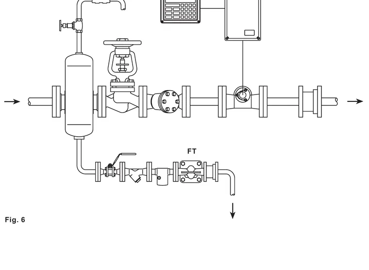
Typical steam and condensate installation set showing an FT ball float steam trap downstream of steam equipment
Typical installation arrangement: steam equipment, isolation, strainer, FT trap and condensate outlet.

1. Safety information

Safe operation of the FT44 can only be guaranteed when it is installed, commissioned, used and maintained by qualified personnel in accordance with this guide. Plant installation rules, pipeline safety procedures and the correct use of tools and protective equipment also apply.

1.1 Intended use

Check the guide, nameplate and technical information before installation to confirm that the FT44 is suitable for the intended application. The documented fluid groups include steam, air and water or condensate in Group 2 service. For any other fluid, confirm material compatibility, pressure, temperature and the consequences of a failure with the manufacturer.

  • Confirm that the body and internal materials are suitable for the system fluid and conditions.
  • Confirm that system pressure and temperature remain within the applicable FT44 size-range limits.
  • Provide a safety device where the product limit is lower than the system condition or where failure could cause overpressure or overtemperature.
  • Do not reverse the inlet and outlet. Follow the flow arrow on the body.
  • Prevent external loads from the pipework, supports or thermal movement from being applied to the trap.

1.2 Work environment and access

Provide safe access, adequate lighting, lifting arrangements for heavy components and sufficient clearance for inspection and maintenance. Consider hot surfaces, steam, condensate, hazardous substances, moving machinery, noise and any work at height before starting work.

1.3 Pressure, temperature and permits

Isolate and safely vent the system before loosening any connection. Double isolation and a locked or labelled valve arrangement may be necessary. A pressure gauge reading zero does not prove that the system is depressurised. Allow the trap to cool to room temperature before maintenance. All work must be completed or supervised by a competent person under the applicable permit-to-work system.

1.4 Residual hazards, freezing and disposal

The external surface may exceed 300 deg C at maximum permitted conditions. The FT44 is not self-draining, so protect it from freezing where the ambient temperature can fall below the freezing point and take care when removing it from a system. The product is recyclable when disposed of responsibly; handle contaminated returns with written hazard information and suitable protection.

2. General product information

2.1 Description

FT44 is a carbon steel ball float steam trap with stainless steel working internals and a built-in automatic air vent. It is supplied with integral flanged connections and can be maintained without disturbing the pipework when suitable isolation and access are provided. The body casting is produced by an approved foundry.

The standard FT44 is horizontal. The vertical installation version is identified by the suffix V, as in FT44V, and the flow direction is downwards only. A manual adjustable needle valve can be supplied as FT44-C for steam-lock release on a horizontal FT44. The top cover or bottom of the body can be drilled and tapped for the documented balance-pipe or drain-valve connection where the option is specified at order.

2.2 Air vent and certification

The BP99/32 capsule is used for the documented superheated-steam range. The standard automatic vent arrangement and the optional steam-lock-release arrangement must not be treated as interchangeable without checking the applicable product configuration. A manufacturer's Typical Test Report is available. EN 10204 3.1 certification can be supplied for FT44 when requested at order placement.

3. Installation

Note: Read the safety information in Section 1 before any installation work.

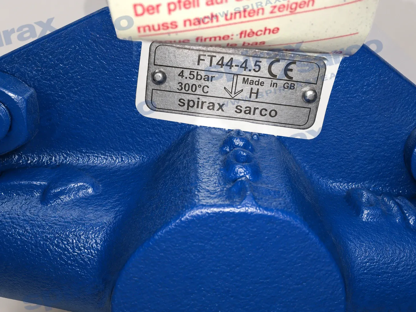
Warning: Install the FT44 with the flow direction shown on the body. The float arm must be in a horizontal plane so that the float can rise and fall vertically. When correctly installed, the body marking and nameplate will be the correct way up.

  1. Check the material, pressure and temperature limits against the intended duty. If the product limit is lower than the system condition, provide a suitable safety device.
  2. Determine the correct installation location and fluid-flow direction. Remove all protective covers from connections and any protective film from nameplates before installing into a steam or high-temperature system.
  3. For a horizontal FT44, use the body arrow. When facing the body, the documented direction is left to right for DN15-DN25 and right to left for DN40-DN50. FT44V is downflow only.
  4. Fit the trap below the outlet of the steam system where possible. A small drop leg immediately before the trap helps prevent steam from reaching the trap in a way that reduces drainage performance.
  5. Fit an upstream strainer where the system arrangement requires it and follow sound engineering practice for steam quality and regular maintenance.
  6. Install isolation valves so the trap can be safely removed or serviced. Support the piping independently and avoid forcing misaligned pipework into position.
  7. For a closed condensate return, fit a downstream non-return valve where reverse flow or backpressure can occur. For an atmospheric discharge, terminate the outlet in a safe place; the discharge may be about 100 deg C. A diffuser is recommended for exposed discharge.
  8. Leave enough clearance to withdraw the cover. The guide specifies a maximum cover-withdrawal distance of approximately 200 mm for the relevant arrangement; verify the actual space against the selected size and flange configuration.

4. Commissioning

After installation or maintenance, confirm that the system is fully functional and that alarms or protective devices operate correctly. Open isolation valves slowly to avoid system shock. Check all joints for leakage and confirm that the trap discharges condensate correctly under the available operating differential pressure.

5. Operation

The FT44 is a continuous trap. At start-up, the automatic air vent allows air and cold condensate to clear; as steam reaches the trap, the vent closes and the float-operated main valve responds to the condensate level. The float falls to close the valve when the condensate has been discharged. The start-up tables in the technical information give the additional cold-water discharge that can be provided by the air-vent function.

Monitor the installation for waterhammer, leakage, abnormal noise, excessive backpressure and changes in condensate load. If the return system is closed, maintain the required non-return protection and ensure that downstream pressure remains within the FT44 limit.

6. Maintenance and spare parts

6.1 General maintenance conditions

Before any maintenance programme, observe the safety information. With suitable isolation, repairs can be completed with the trap in the pipeline. Isolate the supply and return, vent pressure safely to atmosphere, allow the product to cool, and confirm that the joint faces and work area are safe. When reassembling, ensure that the joint faces are clean and that the locating dowel is correctly positioned. Use genuine replacement parts and the recommended tools and torque values.

The cover gasket may contain a thin stainless steel support ring. Handle and dispose of it carefully to avoid physical injury. Do not reuse damaged gaskets, do not apply unapproved gasket paste to the seat or gasket faces, and do not use a pipe wrench on the cover where it could distort the component.

6.2 DN15-DN50 service arrangements

  • For DN15, DN20 and DN25, remove the support frame, pivot frame and valve seat as described in the guide, fit a clean gasket and re-centre the float mechanism before tightening.
  • For DN40 and DN50, remove the main valve assembly and gasket; refit the erosion-deflector arrangement where supplied and tighten the hardware evenly.
  • The capsule or bimetallic air-vent assembly is serviced by removing the assembly and gasket, cleaning the faces and fitting the replacement parts to the recommended torque.
  • The FT44-C steam-lock-release and air-vent arrangement must be ordered and serviced as the documented option, not mixed with an incompatible air-vent configuration.

6.3 DN80-DN100 service arrangements

For DN80 and DN100, remove the cover and main valve assembly only after the pressure and temperature have been controlled. Replace the main-valve gasket and air-vent gasket as required, check the float and lever, position the locating dowel correctly and tighten the cover and assembly hardware evenly.

ItemSizeFastenerTorque
2DN15, DN20, DN2517 A/F, M10 x 3019-22 Nm
2DN4024 A/F, M12 x 6060-66 Nm
2DN5024 A/F, M16 x 7080-88 Nm
5DN15-DN5017 A/F where specified50-55 Nm
7DN15, DN20, DN25M5 x 202.5-2.8 Nm
7DN4010 A/F, M6 x 2010-12 Nm
7DN5013 A/F, M8 x 2020-24 Nm
17DN15-DN5017 A/F50-55 Nm
19FT44-C22 A/F50-55 Nm
ItemFastenerTorque
2, cover24 A/F, M16 x 5080-88 Nm
7, main valve assembly13 A/F, M8 x 2020-24 Nm
17, air vent assembly17 A/F50-55 Nm

6.6 Available spares

Size or arrangementSpareItem numbers
DN15, DN20, DN25Main valve assembly with float5, 6, 7, 8, 9, 10, 11
DN40 and DN50Main valve assembly with erosion deflector5, 6, 7, 12, 26
DN40 and DN50Ball float and lever8
DN15-DN100Air-vent assembly17, 18
FT44-CSteam-lock-release and capsule air-vent assembly17, 18, 19, 20, 21
DN80 and DN100Main valve assembly5, 6, 7, 12, 26
DN80 and DN100Ball float and lever8
All applicable sizesComplete set of gaskets3, 6, 18, 20 where applicable

Order spares by the description in the applicable table and state the size, FT44 pressure designation, connection orientation and option. For a complete overhaul, follow the guide's quantity recommendation for the selected size and arrangement.

Technical information

DocumentReferenceLanguageDownload
FT44TI-S02-14-ZH简体中文Download
FT44TI-S02-23-ZH简体中文Download
FT44,FT46和FT47浮球式TI-S02-36-ZH简体中文Download

Installation and maintenance

DocumentReferenceLanguageDownload
FT43, FT44, FT46 and FT47 Ball Float Steam TrapsIM-S02-30-ENEnglishDownload

Talk to our technical team

Contact Spirax Sarco for product selection, documentation or replacement guidance.