TD42 Thermodynamic Steam Trap

TD42

TD42 Thermodynamic Steam Trap

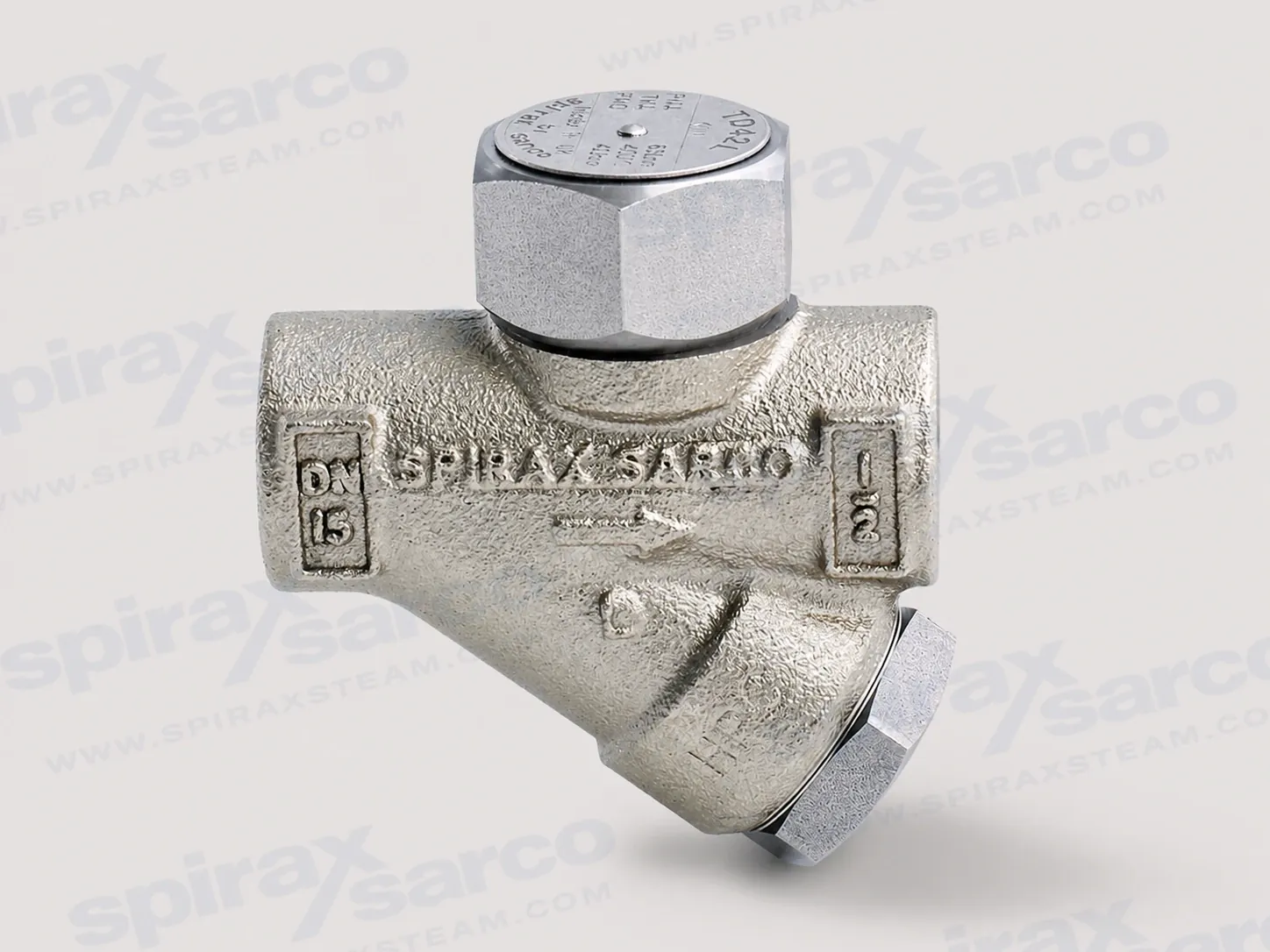
TD42 is a maintainable thermodynamic steam trap with an integral strainer and screwed connections for steam, air or condensate/water service within its documented pressure, temperature, differential-pressure and backpressure limits.

TD42 thermodynamic steam trap for high-pressure steam systems

Spirax Sarco TD42 is a maintainable thermodynamic steam trap for removing condensate from steam systems while retaining steam under the documented operating conditions. Its stainless steel body, screwed connections and integral strainer make it a practical choice where a serviceable trap is required and the installation team needs access to the strainer and seating components for inspection or cleaning.

As a thermodynamic steam trap, the TD42 is intended for a defined engineering duty rather than for unrestricted use in every fluid service. The official installation instructions identify steam, air and condensate or water in Group 2 of the Pressure Equipment Directive as intended fluid groups. If another fluid is being considered, material compatibility, pressure, temperature and the consequences of a malfunction must be checked with the manufacturer before selection.

What the TD42 is designed to do

A thermodynamic steam trap responds to the different pressure and temperature behaviour of condensate and steam. In operation, the TD42 discharges condensate with a blast-type action at a few degrees below steam saturation temperature. This working principle is why the outlet arrangement, discharge safety and backpressure checks belong in the selection review. That discharge characteristic is important when planning the outlet: the discharge point must be safe, and the surrounding pipework and personnel must be suitable for the noise, movement and hot fluid associated with the release.

The trap is suited to steam mains drainage and other condensate-removal duties that fall within its pressure, temperature, differential-pressure and backpressure limits. It is not a substitute for a control valve, a pressure-reducing device or a safety device. The upstream system still needs appropriate isolation, protection and condensate drainage design. A correctly selected trap is only one part of a safe and effective steam system.

For engineers reviewing the wider selection, the steam trap selection guide provides the broader context. The TD42 page remains focused on the single model and on the conditions that must be checked before ordering.

Serviceable construction with integral filtration

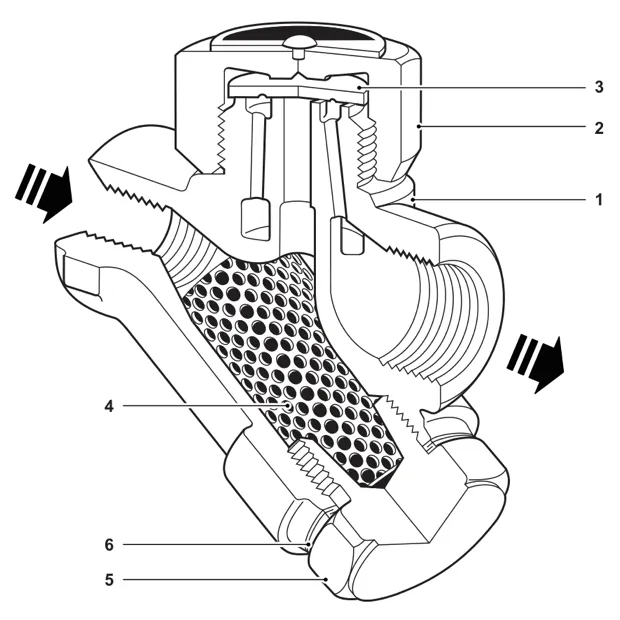
The TD42 combines the trap body and strainer in one assembly. The integral screen provides a filtration stage before the seating area, while the removable cap and strainer cap provide access for planned service. This arrangement is useful during commissioning and maintenance because the screen can be withdrawn, cleaned or replaced without treating the whole trap as a disposable unit. It should not be confused with separate steam strainers and filters installed elsewhere in a line; the TD42 screen is part of the trap assembly.

Official material data identify stainless steel for the principal pressure-containing and working parts: ASTM A743 Grade CA 40 for the body, AISI 416 for the cap and strainer cap, BS 1449 420 S45 for the disc, ASTM A240 316L for the strainer screen, and BS 1449 304 S16 for the strainer cap gasket. These material designations should be retained in the procurement record and checked against the actual fluid and system environment; they are not a licence to ignore corrosion, contamination or temperature compatibility.

An aluminium insulating cover is available as an optional extra. It is intended to reduce the influence of excessive heat loss from wind, rain or low outside temperatures. An integral BDV1 or BDV2 blowdown valve can also be fitted to the strainer cap, or the cap can be prepared with the documented 3/8 inch threaded connection for a suitable plugged arrangement. Options should be confirmed at the time of order because they affect the installed configuration and the available maintenance space.

Pressure, temperature and backpressure envelope

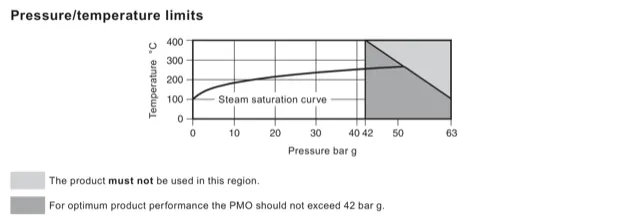
The TD42 has a PN63 body design condition. Its maximum allowable pressure is 63 bar g at 100 °C, while the maximum allowable and operating temperature is 400 °C at 42 bar g. The recommended maximum operating pressure is 42 bar g. These values are conditional limits, not a general permission to operate at any pressure and temperature combination: the pressure/temperature relationship and the shaded prohibited region in the official chart must be observed together.

The documented minimum allowable and operating temperature is 0 °C. The technical information advises consultation for lower operating temperatures. The minimum operating differential pressure for satisfactory operation is 0.25 bar g. Differential pressure is the pressure available to drive condensate through the trap, so it must be checked at the actual operating point, including start-up and low-load conditions.

Backpressure is equally important. The maximum operating backpressure must not exceed 80% of the upstream pressure under any operating condition; beyond that relationship the trap may not shut off. This check must include the return header, other traps discharging into the return system, lift, control-valve effects and any downstream restrictions. The technical data also state that the product is safe for use under full vacuum conditions and give a designed maximum cold hydraulic test pressure of 95 bar g. A hydraulic test limit must not be confused with an allowable operating pressure.

Choosing a Spirax Sarco TD42 steam trap: size and duty

For the TD42 scope covered here, the documented nominal sizes are 3/8 inch, 1/2 inch and 3/4 inch. Connections are screwed BSP T Rp (ISO 7-1) or NPT. Select the size from the actual condensate load and available differential pressure, then confirm that the chosen thread standard matches the piping, fittings and local practice. This is the core of steam trap sizing: nominal connection size alone does not establish capacity or suitability.

Before the order is released, record the normal and maximum inlet pressure, start-up pressure, operating and maximum temperature, minimum differential pressure, expected backpressure, condensate load, fluid service, connection standard and discharge arrangement. Also check whether the optional insulation or blowdown arrangement is needed, whether a downstream non-return valve is required, and whether there is enough clearance to remove the cap and strainer screen. A Spirax Sarco TD42 selection should therefore be reviewed against the complete operating case before the connection options are treated as final.

TD42 steam trap installation and system integration

The TD42 is designed for installation with the capsule in a horizontal plane and the cover at the top. The installation instructions preferably call for a small drop leg before the trap. Isolation valves upstream and downstream allow the trap to be safely inspected, cleaned or replaced. Open those valves slowly until normal operating conditions are reached, then check for leaks and correct operation.

When condensate discharges into a closed return line, a downstream non-return valve is recommended where return flow or backpressure could occur; review a suitable steam check valve for that return-line requirement. When the discharge is to atmosphere, it must terminate in a safe location; the installation instructions warn that the discharged fluid may be at 100 °C. A steam diffuser is recommended for atmospheric discharge, and a sight glass or Spiratec system can be considered where the operating condition needs to be tested. A sight glass should be positioned at least 1 m downstream of a blast-action trap.

The discharge behaviour and the horizontal orientation should be included in the piping review, not left to the final installation stage. Do not support the trap by forcing pipework into alignment, and account for external stresses induced by the connected system. The installer remains responsible for reducing those stresses and for providing safe access, lighting, lifting arrangements and protective equipment.

Maintenance access and ordering checks

For TD42 steam trap maintenance, service can be completed with the trap in the pipeline after the supply and return lines have been isolated, pressure has been safely vented to atmosphere and the product has been allowed to cool. The body and cap joint faces should be clean during reassembly. The instructions recommend using genuine replacement parts, new gaskets where required, suitable tools and appropriate protective equipment. After service, open the isolation valves slowly and check for leaks.

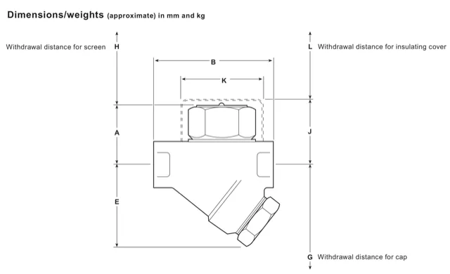
Allow clearance for the screen, cap and optional cover withdrawal distances shown in the dimension drawing. Do not use Stillsons or a similar wrench on the cap, because distortion can result. The disc should be replaced when servicing the seating assembly; if the body seating faces are lapped, the total metal removed must not exceed 0.25 mm. Correct tightening torque and the specified high-temperature anti-seize or molybdenum disulphide grease are part of the maintenance procedure, not optional finishing details.

Certification or inspection requirements must be stated at the time of order. The manufacturer’s Typical Test Report is available for the product when requested. An accurate enquiry should therefore include the model, nominal size, BSP or NPT connection, operating duty, optional extras, certification requirement and discharge arrangement. This information lets the final configuration be checked against the TD42 technical and installation limits before it enters service.

TD42 selection summary

  • Maintainable thermodynamic steam trap with an integral strainer and screwed body connections.

  • Target sizes of 3/8 inch, 1/2 inch and 3/4 inch with BSP T Rp (ISO 7-1) or NPT connections.

  • PN63 body design condition, 42 bar g recommended maximum operating pressure and 400 °C at 42 bar g maximum operating temperature.

  • Minimum satisfactory operating differential pressure of 0.25 bar g and maximum backpressure of 80% of upstream pressure.

  • Horizontal capsule installation with the cover at the top, isolation for service and non-return protection where the return system requires it.

Spirax Sarco TD42 should be specified against the complete operating case, not against a catalogue number alone. The technical tables and installation instructions that follow preserve the detailed limits, dimensions, materials, safety conditions and service sequence needed to complete that check. For a Spirax Sarco TD42 enquiry, retaining the operating data and connection standard with the model reference makes the final review more reliable.

Description

The TD42 is a maintainable thermodynamic steam trap with an integral strainer and screwed body connections.

Standards

This product fully complies with the requirements of the European Pressure Equipment Directive 2014/68/EU.

Certification

This product is available with a manufacturer’s Typical Test Report. All certification and inspection requirements must be stated at the time of order placement.

Sizes and pipe connections

3/8 inch, 1/2 inch and 3/4 inch screwed BSP T Rp (ISO 7-1) or NPT.

Optional extras

Insulating cover: helps prevent the trap being unduly influenced by excessive heat loss, such as when subjected to low outside temperatures, wind or rain.

Integral blowdown valve: a BDV1 or BDV2 can be fitted to the strainer cap. Alternatively, the strainer cap can be drilled, tapped and plugged with a 3/8 inch BSP T Rp (ISO 7-1) or NPT connection.

TD42 thermodynamic steam trap cutaway showing the disc and integral strainer
TD42 cutaway: body, cap, disc, strainer screen, strainer cap and strainer cap gasket.

Materials

No.

Part

Material

1

Body

Stainless steel ASTM A743 Gr. CA 40

2

Cap

Stainless steel AISI 416

3

Disc

Stainless steel BS 1449 420 S45

4

Strainer screen

Stainless steel ASTM A240 316L

5

Strainer cap

Stainless steel AISI 416

6

Strainer cap gasket

Stainless steel BS 1449 304 S16

7

Insulating cover (optional extra)

Aluminium

Pressure/temperature limits (ISO 6552)

TD42 pressure and temperature limits chart with the 42 bar g operating pressure boundary
The shaded region is prohibited; for optimum performance PMO should not exceed 42 bar g.

Pressure and temperature data

Body design conditions

PN63

PMA maximum allowable pressure

63 bar g @ 100 °C

TMA maximum allowable temperature

400 °C @ 42 bar g

Minimum allowable temperature

0 °C

PMO maximum operating pressure

42 bar g recommended

TMO maximum operating temperature

400 °C @ 42 bar g

Minimum operating temperature

0 °C; consult the manufacturer for lower temperatures

PMOB maximum backpressure

Must not exceed 80% of inlet pressure under any operating condition, otherwise the trap may not shut off

Minimum operating differential pressure

0.25 bar g

Vacuum service

Safe for use under full vacuum conditions

Maximum cold hydraulic test pressure

95 bar g

Capacity

Condensate capacity depends on connection size and operating differential pressure. Confirm the actual condensate load, available differential pressure and the complete pressure/temperature case before selection; the nominal connection size is not a capacity value.

Dimensions and weights

TD42 dimension diagram showing cap, strainer and insulating cover withdrawal distances
Dimensions are approximate and in mm; the drawing identifies withdrawal distances for the screen, cap and optional insulating cover.

Size

A

B

E

G

H

J

K

L

Weight kg

3/8 inch

41

78

55

85

41

57

57

38

0.75

1/2 inch

41

78

55

85

41

57

57

38

0.80

3/4 inch

47

90

60

100

41

63

57

38

1.00

Installation note

The TD42 is designed for installation with the capsule in a horizontal plane and the cover at the top. A downstream non-return valve is recommended when condensate is discharged into return lines where backpressure is experienced. A diffuser is recommended for discharge to atmosphere. For ease of maintenance, consider isolation valves upstream and downstream.

For complete safety, installation, commissioning, operation and maintenance instructions, see IM-P068-24.

Disposal

The product is recyclable. No ecological hazard is anticipated with disposal, provided due care is taken and local recycling and disposal regulations are followed.

How to order

Example: 1 off 1/2 inch TD42 thermodynamic steam trap having screwed BSP T Rp (ISO 7-1) connections.

Spare parts

The available spare parts are:

Available spare

Item

Disc (packet of 3)

3

Strainer screen and gasket

4, 6

Insulating cover

7

Strainer cap gasket (packet of 3)

6

Order spares using the description in the available-spares list and state the size and type of trap.

Part

Tool size

Torque N m

Cap, 3/8 inch

36 A/F

135–150

Cap, 1/2 inch and 3/4 inch

41 A/F

180–200

Strainer cap

32 A/F, M28

170–190

1. Safety information

Safe operation of this product can only be guaranteed if it is properly installed, commissioned, used and maintained by qualified personnel in compliance with the operating instructions. General installation and safety instructions for pipeline and plant construction, and the proper use of tools and safety equipment, must also be followed.

1.1 Intended use

Check the installation and maintenance instructions, name-plate and technical information sheet to confirm that the product is suitable for the intended use and application. The product complies with the European Pressure Equipment Directive 2014/68/EU and falls within category SEP; products in this category are not required by the Directive to carry the CE mark.

  • The product is specifically designed for steam, air or condensate/water in Group 2 of the Directive. Other fluids may be possible, but suitability must be confirmed with the manufacturer.

  • Check material suitability, pressure and temperature, including their maximum and minimum values. If the product operating limits are lower than those of the system, provide a safety device to prevent overpressure or overtemperature.

  • Determine the correct installation situation and direction of fluid flow.

  • Consider external stresses induced by the connected system and take adequate precautions to minimise them.

  • Remove protection covers from connections and protective film from name-plates where appropriate before installation on steam or other high-temperature services.

1.2 Access

Ensure safe access and, where necessary, a suitably guarded working platform before working on the product. Arrange suitable lifting gear if required.

1.3 Lighting

Provide adequate lighting, particularly where detailed or intricate work is required.

1.4 Hazardous liquids or gases

Consider what is in the pipeline or what may have been in it previously, including flammable materials, substances hazardous to health and extremes of temperature.

1.5 Hazardous environment

Consider explosion risk areas, lack of oxygen, dangerous gases, extremes of temperature, hot surfaces, fire hazards during welding, excessive noise and moving machinery.

1.6 The system

Consider the effect of the proposed work on the complete system. Closing isolation valves or isolating equipment must not put other plant or personnel at risk. Isolation valves should be opened and closed gradually to avoid system shocks.

1.7 Pressure systems

Isolate pressure, safely vent to atmospheric pressure and consider double isolation with block and bleed plus locking or labelling of closed valves. Never assume that a system is depressurised just because a pressure gauge reads zero.

1.8 Temperature

Allow time for temperature to normalise after isolation to avoid burns.

1.9 Tools and consumables

Use suitable tools and consumables, and use only genuine replacement parts.

1.10 Protective clothing

Assess whether personnel require protective clothing against chemicals, high or low temperature, radiation, noise, falling objects and eye or face hazards.

1.11 Permits to work

All work must be carried out or supervised by a suitably competent person. Installation and operating personnel should be trained in correct use. Follow a formal permit-to-work system where one exists; otherwise a responsible person should know what work is in progress and arrange an assistant where necessary. Post warning notices if required.

1.12 Handling

Assess manual-handling risks, considering the task, individual, load and working environment. Use suitable handling methods for lifting, pushing, pulling, carrying or supporting the product.

1.13 Residual hazards

The external surface may be very hot in normal use. At maximum permitted operating conditions the surface temperature of some products may reach 500 °C. Many products are not self-draining; take care when dismantling or removing the product and refer to the maintenance instructions.

1.14 Freezing

Protect products that are not self-draining against frost damage where they may be exposed to temperatures below freezing.

1.15 Disposal

Unless otherwise stated, the product is recyclable and no ecological hazard is anticipated when it is disposed of with due care. Check current compliance information and local recycling and disposal regulations.

1.16 Returning products

When returning products, provide written information about hazards and precautions required because of contamination residues or mechanical damage, including health and safety data sheets for hazardous or potentially hazardous substances.

2. General product information

2.1 General description

The TD42 is a maintainable thermodynamic steam trap suitable for pressures up to 42 bar g, complete with integral strainer and screwed body connections.

An insulating cover is available to reduce the influence of excessive heat loss. A BDV1 or BDV2 integral blowdown valve can be fitted to the strainer cap, or the cap can be drilled, tapped and plugged with the documented threaded connection.

For detailed technical data, pressure/temperature limits and dimensions, see TI-P068-22.

3. Installation

Before installation, observe all safety information and check the materials, pressure, temperature and their maximum values against the intended system.

  1. Determine the correct installation situation and direction of fluid flow.

  2. Remove protective covers from connections and protective film from name-plates where appropriate.

  3. Preferably install the trap in the horizontal plane with a small drop leg preceding it. Install suitable isolation valves for safe maintenance and trap replacement.

  4. Provide a suitable method for testing operation, such as a sight glass or Spiratec system. Position a sight glass at least 1 m downstream of a blast-action trap.

  5. When discharging into a closed return system, fit a downstream non-return valve to prevent return flow.

  6. Open isolation valves slowly until normal operating conditions are achieved. Check for leaks and correct operation.

If the trap discharges to atmosphere, discharge to a safe place; the discharged fluid may be at 100 °C.

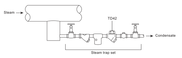
Typical TD42 steam trap set showing steam entering and condensate leaving the trap
Typical application: steam enters the trap set upstream of TD42 and condensate leaves downstream.

4. Commissioning

After installation or maintenance, ensure that the system is fully functional and test alarms or protective devices.

5. Operation

The thermodynamic steam trap discharges condensate with a blast-type action at a few degrees below steam saturation temperature. Give due care to the location of the discharge.

6. Maintenance

6.1 General information

  • Before maintenance, isolate the trap from both the supply and return lines, allow pressure to normalise safely to atmosphere and allow the trap to cool.

  • When reassembling, ensure that joint faces are clean.

  • Maintenance can be completed with the trap in the pipeline once safety procedures have been observed.

  • Use new gaskets and spares where recommended, and use correct tools and protective equipment.

  • When maintenance is complete, open isolation valves slowly and check for leaks.

Item/part

Size or tool

Torque N m

lbf ft

Cap, 3/8 inch

36 A/F

135–150

100–110

Cap, 1/2 inch and 3/4 inch

41 A/F

180–200

132–147

Strainer cap

32 A/F, M28

170–190

125–140

6.2 How to service

  1. Remove the insulating cover if fitted and unscrew the cap using a suitable spanner or socket. Do not use Stillsons or a similar wrench, which may distort the cap.

  2. If the body seating faces are only slightly worn, reface them by lapping on a flat surface such as a surface plate, using a figure-of-eight motion and suitable grinding compound.

  3. If wear is too great for lapping alone, grind the seating faces flat and then lap them. The disc should always be replaced with a new one, and the total metal removed must not exceed 0.25 mm.

  4. When reassembling, place the disc with the grooved side in contact with the body seating face. Tighten the cap to the recommended torque. No gasket is required at the cap, but apply a suitable high-temperature anti-seize grease to the threads.

6.3 How to clean or replace the strainer

  1. Unscrew the strainer cap using a suitable spanner.

  2. Withdraw the screen and clean it, or replace it if damaged.

  3. Insert the screen into the strainer cap, then screw the cap into place. Apply a fine smear of molybdenum disulphide grease to the first few threads. Ensure that the gasket and gasket faces are clean.

  4. Tighten to the recommended torque.

  5. When maintenance is complete, open isolation valves slowly and check for leaks.

7. Spare parts

Available spare

Item

Disc (packet of 3)

3

Strainer screen and gasket

4, 6

Insulating cover

7

Strainer cap gasket (packet of 3)

6

Order spares using the description in the available-spares list and state the size and type of trap.

Technical information

DocumentReferenceLanguageDownload
TD42TI-P068-22-ENEnglishDownload

Installation and maintenance

DocumentReferenceLanguageDownload
TD42IM-P068-24-ENEnglishDownload

Talk to our technical team

Contact Spirax Sarco for product selection, documentation or replacement guidance.