
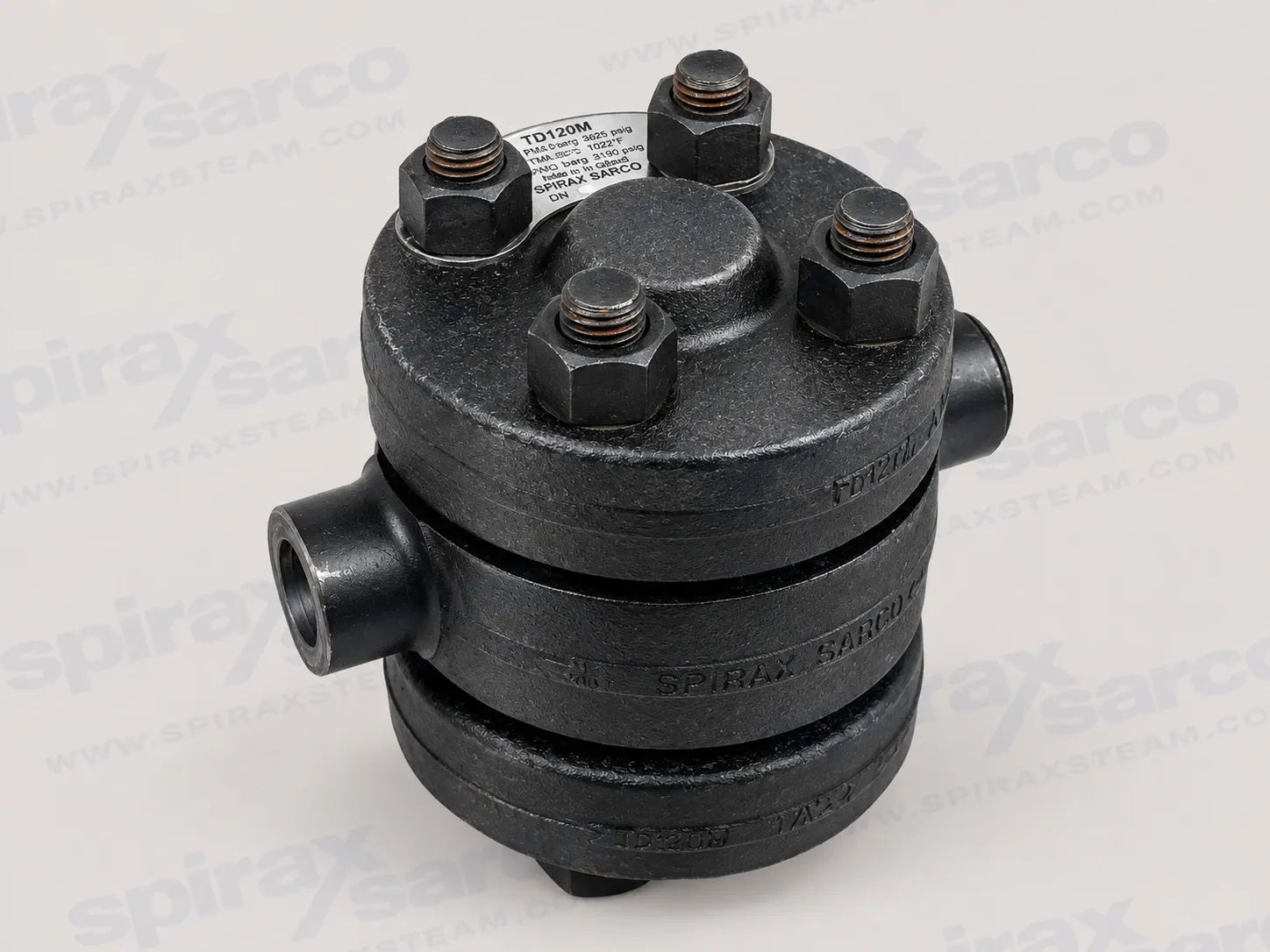
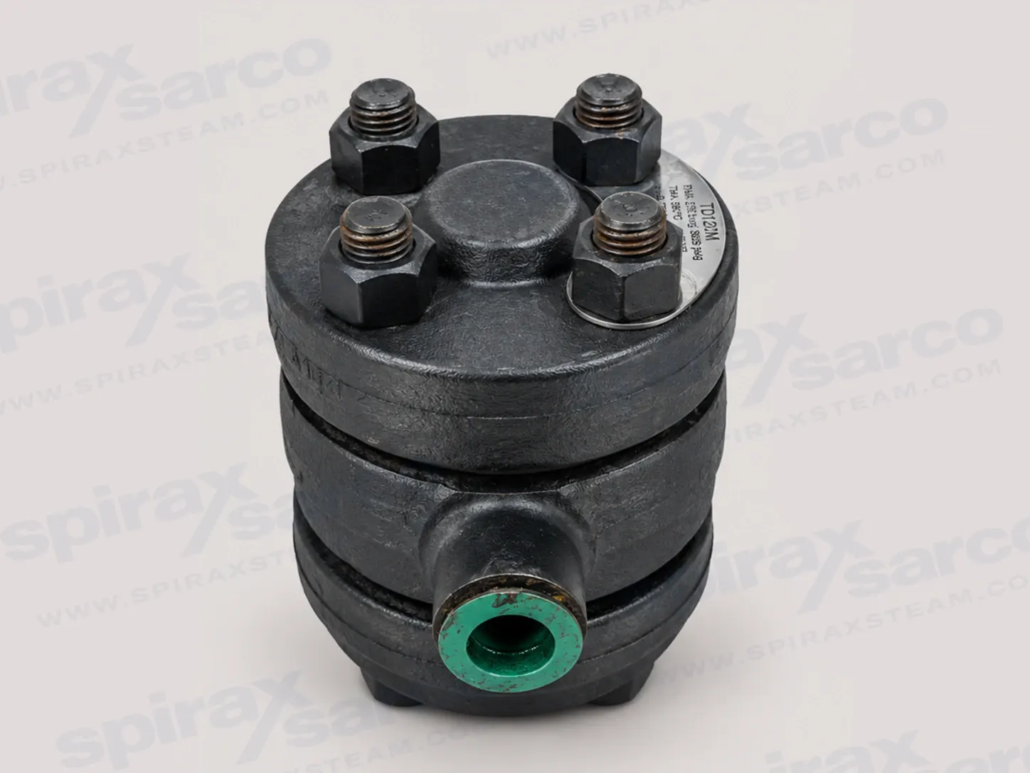
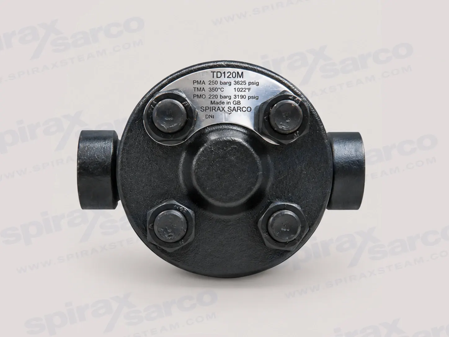
TD120M
TD120M High Pressure Thermodynamic Steam Trap
TD120M is a maintainable high-pressure thermodynamic steam trap with an integral strainer and replaceable seat for low-capacity superheated steam main drainage, with documented pressure and temperature conditions up to 250 bar g.
Spirax Sarco TD120M high-pressure thermodynamic steam trap for superheated main drainage
Spirax Sarco TD120M is a maintainable high-pressure thermodynamic steam trap with an integral strainer and replaceable seat. It is a low-capacity model specifically documented for superheated steam main drainage applications up to 250 bar g. The replaceable seat and accessible strainer make the trap suitable for installations where the seat, disc, gaskets and strainer screen must be inspected or renewed as part of a planned maintenance programme.
The model is intended to be selected as part of a complete drainage point, not by nominal pipe size alone. The required connection, pressure-temperature case, available differential pressure, condensate load, return-line backpressure and access for maintenance all affect the final choice. The official installation instructions identify steam, air and condensate/water in Group 2 service as the intended media boundary; any other fluid requires a separate suitability review.
Thermodynamic operation with a maintainable seat
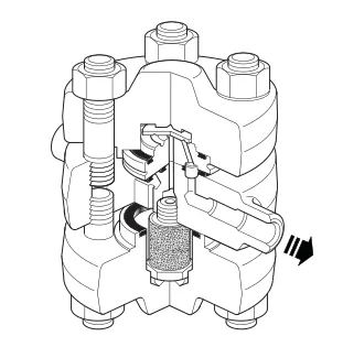
A thermodynamic steam trap uses a disc to control the discharge of condensate and retain live steam. Cool condensate, air and other non-condensable gases enter through the central orifice and lift the disc, allowing discharge through the outlet passage. As the condensate approaches steam temperature, part of it flashes. The high-velocity flash steam passes beneath the disc and builds pressure in the control chamber above it. The resulting pressure imbalance drives the disc onto the seat and stops the flow.
The disc is the only moving part identified in the installation guide. Heat loss from the body eventually lowers the control-chamber pressure, allowing inlet pressure to lift the disc and begin the cycle again. This gives the TD120M a periodic discharge close to steam temperature and tight closure between discharges. In a superheated main, the low-capacity characteristic is important: the trap is intended to remove the drainage load without being treated as a general-purpose high-volume condensate device.
The integral strainer helps prevent dirt and scale from reaching the disc and seating surfaces. It is still necessary to assess pipe cleanliness and the likely particle load. The installation guide notes that particles trapped between the disc and seat can cause rapid wear and erosion, so a separate strainer or dirt pocket may provide additional protection where the system requires it. The integral screen is part of the trap assembly; it does not remove the need to design the upstream drainage arrangement correctly.
Connections and configuration choices
TD120M is available with several high-pressure connection arrangements. Butt-weld ends are offered in 1/2 inch, 3/4 inch and 1 inch sizes to suit Schedule 160 pipe. Socket-weld ends are offered in the same sizes to ASME (ANSI) B16.11 Class 6000. The integral flange options cover DN15 and DN25 to EN 1092 PN160 and PN250, and DN15, DN20 and DN25 to EN 1092 PN100 or ASME (ANSI) Class 600, Class 900 and Class 1500.
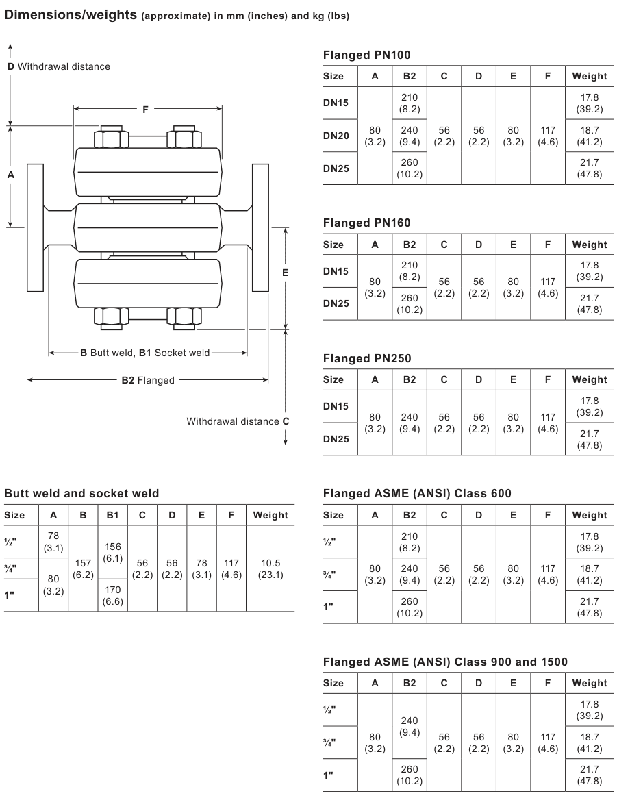
These alternatives do not represent interchangeable dimensions. A welded installation must be checked against the pipe schedule and approved welding procedure; a flanged installation must be checked against the nominal diameter, flange class, bolt access and removal clearance. The dimensions drawing later in this page gives approximate A to F dimensions and weights for the documented connection groups. Confirm the exact connection and standard on the enquiry so the supplied trap matches the plant design.
The technical sheet describes the body, top cover and bottom cover as alloy steel to ASTM A182 F22. The disc is steel to BS EN ISO 4957, the strainer screen assembly is stainless steel to BS 970 304 S15 or sintered stainless steel, and the replaceable seat is steel to BS 4659 Grade BD2. Cover studs, nuts, gaskets and the stainless-steel ferrule are separately identified in the materials table. These designations support procurement and compatibility review; they are not a substitute for checking the complete system against corrosion, erosion and temperature conditions.
Pressure, temperature and backpressure limits
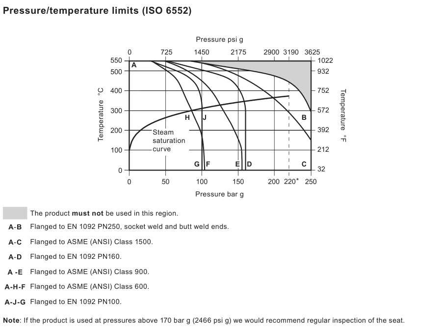
The TD120M body design condition is PN250. Its maximum allowable pressure is 250 bar g at 300 °C, and its maximum allowable temperature is 550 °C at 80 bar g. For saturated steam service, the current technical sheet gives a maximum operating pressure of 220 bar g at 374 °C. The maximum operating temperature is 550 °C at 80 bar g. These are conditional points on a pressure-temperature envelope, rather than independent values that can be combined without checking the graph.
The documented minimum allowable temperature is -29 °C, while the minimum operating temperature is 0 °C; lower operating temperatures require consultation with the manufacturer. Operating backpressure must not exceed 50% of the upstream pressure. The minimum operating differential pressure is 8 bar g. The product is documented as safe under full vacuum conditions, but the 375 bar g cold hydraulic test pressure is a test value and must not be used as a continuous operating rating.
When pressure is above 170 bar g, the technical sheet recommends regular inspection of the seat. This is especially relevant to a high-pressure drainage point because wear, contamination and seating damage can change shut-off behaviour. Review the pressure-temperature graph, the pressure class of the selected connection and the actual start-up, running and shutdown cases together. A maximum pressure number by itself does not establish suitability.
Capacity and selection of the drainage point
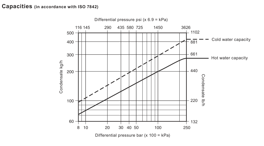
The capacity information is presented against differential pressure, with separate cold-water and hot-condensate curves and a corresponding table. Use the differential pressure actually available across the trap, including the effect of the return header and other discharges. Check both start-up and normal running conditions because the available pressure difference and condensate load can change as the steam main warms. The capacity chart is retained in the technical section so selection can be made from the documented relationship rather than from a single quoted flow number.
TD120M is described as low capacity for superheated main drainage. That description should guide the application review: identify the drain point, the pipe geometry, the expected condensate load and the consequences of retaining water in the main. If the load is close to the curve or the pressure difference is unstable, record the complete operating case for engineering review. Do not use the line size, the maximum allowable pressure or the hydraulic test pressure as a substitute for a capacity check.
Reserve the clearance shown in the dimensions drawing. Access is needed for the removable covers, integral strainer screen, replaceable seat and disc. A trap that fits between two connection faces but cannot be opened safely is not a maintainable installation. Include the withdrawal distance, lifting and working access in the pipe-rack or plant-layout review before the order is released.
Installation and system integration
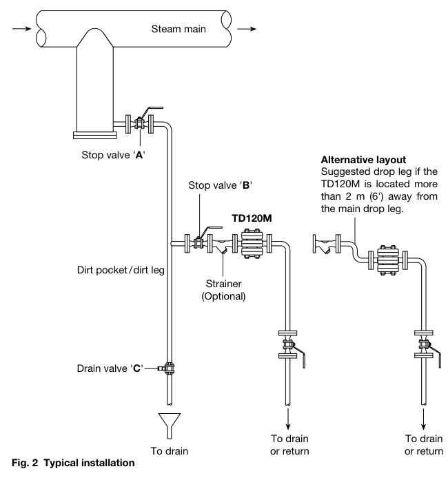
The preferred installation is in a horizontal pipe with the nameplate uppermost. A small drop leg should precede the trap, and the installation guide shows an alternative drop-leg arrangement when the model is more than 2 m (6 ft) from the main vertical drain leg. The flow direction must agree with the nameplate and the intended layout. Other orientations may operate, but the installation guide warns that service life may be affected.
Provide suitable upstream and downstream isolation valves so the trap can be safely maintained or replaced. In a closed return system, fit a downstream non-return valve to prevent reverse flow. If the discharge is to atmosphere, route it to a safe place because the discharged fluid may be at 100 °C (212 °F). Welding, external pipe stresses, access, lighting, lifting arrangements, hazardous contents and protective clothing belong in the installation risk review, not only in the commissioning checklist.
During commissioning, air and debris may need to be vented from the drop leg. The installation guide specifies a controlled sequence using the upstream stop valve, downstream stop valve and drain valve, followed by slow opening to normal operating conditions. After the trap has operated for 24 hours at normal pressure and temperature, the cover nuts must be retightened to restore the correct gasket compression. This step is part of the maintenance plan for a newly installed trap.
Maintenance and ordering checks
Maintenance starts with safe isolation from both supply and return, pressure equalisation to atmosphere and sufficient cooling time. The top cover, disc and replaceable seat can be accessed for inspection or renewal; the bottom cover gives access to the integral strainer screen. The guide requires clean gasket contact surfaces, a new disc when the seat assembly is serviced and correct positioning of the disc grooves. It also warns that the thin stainless-steel support ring in the cover gasket can cause injury if handled or discarded carelessly.
Use only suitable tools and genuine replacement parts. The guide provides dedicated tightening torques for the screen assembly, cover studs and cover nuts, and requires the cover nuts to be tightened in a diagonally opposite sequence. Inspect the strainer screen as part of a scheduled maintenance programme, and check for leaks after the isolation valves are reopened slowly. The available spare categories include cover studs and nuts, the strainer screen and gasket, gasket sets, and a maintenance kit; a spare-parts enquiry should state the size and trap type.
For a Spirax Sarco TD120M enquiry, provide the connection type and size, pipe or flange standard, normal and maximum pressure, temperature, available differential pressure, condensate load, return-line backpressure, discharge destination and maintenance-access arrangement. State any EN 10204 3.1 certification or inspection requirement when ordering. This information allows the selected high-pressure thermodynamic steam trap to be checked against the actual drainage point instead of being specified by model number alone.
TD120M selection summary
- Maintainable high-pressure thermodynamic steam trap with an integral strainer and replaceable seat.
- Low-capacity design specifically documented for superheated steam main drainage up to 250 bar g.
- Butt-weld, socket-weld and integral flange connection options across the documented inch and DN sizes.
- Current saturated-steam operating limit of 220 bar g at 374 °C, with pressure-temperature conditions checked against the official graph.
- Maximum operating backpressure limited to 50% of upstream pressure and minimum operating differential pressure of 8 bar g.
- Horizontal installation with the nameplate uppermost, an inlet drop leg, isolation for maintenance and safe discharge planning.
Use the verified pressure-temperature envelope, capacity curve, connection standard, dimensions and installation instructions together. The detailed technical and installation sections below retain the full tables, drawings, safety conditions, operating description and maintenance sequence for the exact TD120M model.
Description
The TD120M is a maintainable high-pressure thermodynamic steam trap with integral strainer and replaceable seat to ease maintenance. It is available in 1/2 inch, 3/4 inch and 1 inch sizes with socket-weld, butt-weld or flanged connections. It has low capacity and is specifically designed for superheated main drainage applications up to 250 bar g (3626 psi g).
Standards and certification
This product fully complies with the requirements of the European Pressure Equipment Directive 2014/68/EU. Certification to EN 10204 3.1 is available. All certification and inspection requirements must be stated at the time of order placement.
Sizes and pipe connections
| Connection | Documented sizes and standard |
|---|---|
| Butt weld | 1/2 inch, 3/4 inch and 1 inch; Schedule 160 pipe |
| Socket weld | 1/2 inch, 3/4 inch and 1 inch; ASME (ANSI) B16.11 Class 6000 |
| EN integral flange | DN15 and DN25; EN 1092 PN160 and PN250 |
| EN / ASME integral flange | DN15, DN20 and DN25; EN 1092 PN100 and ASME (ANSI) Class 600, 900 and 1500 |
Materials
| No. | Part | Material | Specification |
|---|---|---|---|
| 1 | Body | Alloy steel | ASTM A182 F22 |
| 2 | Disc | Steel | BS EN ISO 4957 |
| 3 | Top cover | Alloy steel | ASTM A182 F22 |
| 4 | Strainer screen assembly | Stainless steel | BS 970 304 S15 / sintered stainless |
| 5 | Bottom cover | Alloy steel | ASTM A182 F22 |
| 6* | Seat | Steel | BS 4659 Grade BD2 |
| 7 | Cover gasket | Spirally wound stainless steel with exfoliated graphite filler | — |
| 8 | Cover studs | Steel | ASTM A193 Grade B16 |
| 9 | Cover nuts | Steel | ASTM A194 Grade 4 |
| 10 | Inner seat gasket | Spirally wound stainless steel with exfoliated graphite filler | — |
| 11 | Cover gasket | Spirally wound stainless steel with exfoliated graphite filler | — |
| 12* | Ferrule | Stainless steel | — |
* Item 12 (ferrule) is pressed into item 6 (seat).
Pressure/temperature limits (ISO 6552)
| Limit | SI value | Imperial value |
|---|---|---|
| Body design conditions | PN250 | — |
| PMA maximum allowable pressure | 250 bar g @ 300 °C | 3625 psi g @ 572 °F |
| TMA maximum allowable temperature | 550 °C @ 80 bar g | 1022 °F @ 1160 psi g |
| Minimum allowable temperature | -29 °C | -20.2 °F |
| PMO maximum operating pressure for saturated steam service | 220 bar g @ 374 °C | 3190 psi g @ 705 °F |
| TMO maximum operating temperature | 550 °C @ 80 bar g | 1022 °F @ 1160 psi g |
| Minimum operating temperature | 0 °C | 32 °F |
| PMOB maximum operating backpressure | Not more than 50% of upstream pressure | — |
| Minimum operating differential pressure | 8 bar g | 116 psi g |
| Vacuum service | Safe under full vacuum conditions | — |
| Maximum cold hydraulic test pressure | 375 bar g | 2438 psi g |
For lower operating temperatures consult Spirax Sarco. If the product is used at pressures above 170 bar g (2466 psi g), regular inspection of the seat is recommended.
Capacities (in accordance with ISO 7842)
| Pressure | Cold water | Hot condensate | Pressure | Cold water | Hot condensate | ||
|---|---|---|---|---|---|---|---|
| bar g | psi g | kg/h (lb/h) | kg/h (lb/h) | bar g | psi g | kg/h (lb/h) | kg/h (lb/h) |
| 8 | 116 | 98 (217) | 71 (156) | 138 | 2000 | 329 (725) | 221 (487) |
| 17 | 250 | 136 (300) | 96 (212) | 155 | 2250 | 346 (762) | 231 (510) |
| 34 | 500 | 183 (403) | 127 (280) | 172 | 2500 | 361 (796) | 241 (532) |
| 52 | 750 | 217 (478) | 149 (329) | 190 | 2750 | 376 (829) | 251 (553) |
| 69 | 1000 | 245 (540) | 167 (369) | 207 | 3000 | 390 (860) | 259 (572) |
| 86 | 1250 | 269 (594) | 183 (404) | 224 | 3250 | 404 (890) | 268 (591) |
| 103 | 1500 | 291 (641) | 197 (434) | 241 | 3500 | 416 (918) | 276 (608) |
| 121 | 1750 | 311 (685) | 209 (461) | 250 | 3625 | 423 (932) | 280 (617) |
Dimensions and weights
Safety information, installation and maintenance
For full details see the selected Installation and Maintenance Instructions (IM-P150-12) supplied with the product. The TD120M is designed for installation with the nameplate on top. For ease of maintenance, consider fitting isolation valves upstream and downstream of the trap.
Disposal
The product is recyclable. No ecological hazard is anticipated with disposal of this product, provided due care is taken and local requirements are followed.
How to order
Example: one 1/2 inch TD120M high-pressure thermodynamic steam trap with an alloy-steel body, integral strainer and butt-weld connections, suitable for superheated steam main drainage. The seat and disc shall be maintainable.
Available spares
| Spare description | Items |
|---|---|
| Set of cover studs and nuts | 8 (8 off), 9 (8 off) |
| Strainer screen and gasket | 4, 11 |
| Set of gaskets | 7 (2 off), 10, 11 |
| Maintenance kit | 2, 4, 7 (2 off), 10, 11, 6 + 12 |
Always state the size and type of trap when ordering spares.
Recommended tightening torques
| Item | Part / tool | N m | lbf ft |
|---|---|---|---|
| 4 | 22 A/F | 25–35 | 18–26 |
| 8 | Stud, M16 | 85–90 | 63–66 |
| 9 | Nut, 23 A/F, M16 | 160–180 | 118–133 |
Installation and Maintenance Guide
- Safety information
- General product information
- Installation
- Commissioning
- Operation
- Maintenance
- Spare parts
Read this guide with the product nameplate and Technical Information Sheet TI-P150-11. Installation, commissioning, use and maintenance must be carried out by qualified personnel in accordance with the instructions and applicable plant safety requirements.
1. Safety information
Safe operation can only be guaranteed when this product is properly installed, commissioned, used and maintained by qualified personnel. General installation and safety instructions for pipeline and plant construction, and the proper use of tools and safety equipment, also apply.
Warning
The cover gasket contains a thin stainless-steel support ring that may cause physical injury if it is not handled and disposed of carefully.
1.1 Intended use
Check the instructions, nameplate and current Technical Information Sheet to confirm suitability for the intended application. The selected guide identifies steam, air or condensate/water in Group 2 service as the intended media boundary. Other fluids require confirmation of suitability from the manufacturer.
Check material suitability, pressure, temperature and all maximum and minimum values. If the product limits are lower than the system limits, or a malfunction could cause dangerous overpressure or overtemperature, provide a safety device to prevent those conditions. Determine the correct installation situation and direction of flow. The product is not intended to withstand external stresses induced by the connected system; the installer must minimise them. Remove connection protection covers and protective film from nameplates before high-temperature installation.
1.2 Access and lighting
Provide safe access and, where necessary, a suitably guarded working platform before work begins. Arrange suitable lifting gear where required. Provide adequate lighting, particularly for detailed or intricate work.
1.3 Pipeline contents and environment
Consider what is in the pipeline, or may previously have been in it, including flammable materials, substances hazardous to health and extreme temperatures. Consider explosion-risk areas, lack of oxygen, dangerous gases, hot surfaces, fire risk during welding, excessive noise and moving machinery around the product.
1.4 The complete system
Consider the effect of the proposed work on the complete system. Closing isolation valves or isolating another service must not put personnel or other plant equipment at risk. Do not isolate vents or protective devices or render controls and alarms ineffective. Operate isolation valves gradually to avoid system shocks.
1.5 Pressure systems
Isolate pressure and safely vent to atmospheric pressure before work. Consider double isolation, double block and bleed, and locking or labelling closed valves. Never assume that the system is depressurised merely because a pressure gauge reads zero.
1.6 Temperature
Allow time for the temperature to normalise after isolation to avoid burns. In normal use the external surface may be very hot; at the maximum permitted operating conditions some surfaces may reach 550 °C (1022 °F). Many products are not self-draining, so take care when dismantling or removing the trap.
1.7 Tools, consumables and protective clothing
Have suitable tools and consumables ready before work begins. Use only genuine replacement parts. Assess the need for protective clothing against chemicals, high or low temperature, radiation, noise, falling objects and hazards to the eyes and face.
1.8 Permits and competence
All work must be carried out or supervised by suitably competent personnel. Installation and operating personnel must be trained in correct use. Comply with a formal permit-to-work system where one exists; otherwise ensure a responsible person knows what work is taking place and arrange a safety assistant where necessary. Post warning notices if required.
1.9 Handling and freezing
Manual handling of large or heavy products can cause injury. Assess the task, load, person and environment and use an appropriate handling method. Protect products that are not self-draining against frost damage wherever they may be exposed to temperatures below freezing.
1.10 Disposal and returned products
The product is recyclable and no ecological hazard is anticipated when it is disposed of with due care. When returning a product, provide written information about contamination residues, mechanical damage, hazards and precautions, including relevant safety data sheets.
2. General product information
2.1 General description
The TD120M is a maintainable high-pressure thermodynamic steam trap with integral strainer and replaceable seat to ease maintenance. It has low capacity and is specifically designed for superheated main drainage applications up to 250 bar g (3625 psi g). For current pressure, temperature and connection limits, use TI-P150-11 CMGT Issue 6.
2.2 Standards and certification
The selected installation guide is an older issue and contains a historical regulatory reference. The current TI-P150-11 cites European Pressure Equipment Directive 2014/68/EU and states that EN 10204 3.1 certification is available. State certification and inspection requirements at order placement.
2.3 Sizes and pipe connections
Butt-weld ends are available in 1/2 inch, 3/4 inch and 1 inch for Schedule 160 pipe. Socket-weld ends are available in the same sizes to ASME (ANSI) B16.11 Class 6000. Integral flanges are documented for DN15 and DN25 to EN 1092 PN160 and PN250, and for DN15, DN20 and DN25 to EN 1092 PN100 and ASME (ANSI) Class 600, 900 and 1500.
2.4 Pressure and temperature check (ISO 6552)
Check the current TI-P150-11 pressure-temperature graph and table before selecting the trap. The current sheet gives PMA 250 bar g at 300 °C, TMA 550 °C at 80 bar g, PMO for saturated steam 220 bar g at 374 °C, TMO 550 °C at 80 bar g, minimum operating temperature 0 °C, maximum backpressure 50% of upstream pressure and minimum operating differential pressure 8 bar g. The older manual's legacy rating row is not a substitute for the current sheet.
3. Installation
Before installation, observe all safety information in Section 1. Using the instructions, nameplate and current Technical Information Sheet, check that the product is suitable for the intended installation.
- Check the system limits. Check materials, pressure and temperature and their maximum values. If a product limit is lower than the system limit, provide a safety device to prevent overpressurisation.
- Confirm the situation and flow. Determine the correct installation situation and direction of fluid flow. The typical layout is shown below.
- Prepare the connections. Remove protection covers from connections and protective film from nameplates before installation on steam or other high-temperature applications.
- Install in the preferred position. Install in a horizontal pipe with the nameplate uppermost. The trap can operate in other positions, but service life may be affected. Provide a small drop leg preceding the trap and access for removing the integral strainer screen.
- Provide isolation and return protection. Install suitable isolation valves for safe maintenance and replacement. Where the trap discharges into a closed return system, fit a downstream non-return valve to prevent reverse flow.
- Open slowly and check. Open isolation valves slowly until normal conditions are reached to avoid system shocks. Check for leaks and correct operation, and use the correct tools, safety procedures and protective equipment.
- Protect the seating surfaces. The disc and seating surfaces are produced to a high degree of flatness for good high-pressure shut-off. The integral strainer helps prevent dirt and scale entering the trap; a separate strainer or dirt pocket may provide additional protection.
- Weld correctly. For socket-weld or butt-weld connections, welding must follow an approved procedure to a recognised standard.
If the trap discharges to atmosphere, discharge to a safe place. The discharged fluid may be at 100 °C (212 °F). Consider the external stresses induced by the connected system.
4. Commissioning
Initial start-up can take several hours or days to reach normal operating pressure and temperature. Even when replacing a trap while the main system remains in service, it may be necessary to vent air from the drop leg. If the trap is some distance from stop valve A, the pipework between A and the trap can air-lock because the trap closes to air and does not readily allow steam into the pipework.
- Keep stop valve B closed and drain valve C open.
- Slowly and partially open stop valve A to discharge air, condensate and pipe debris.
- Fully close valve C, then slowly open valves A and B to the fully open position.
- If the trap is more than 2 m (6 ft) from the vertical drain leg, provide a suitable inlet drop leg to improve service life and avoid a mixture of steam and condensate at the trap.
Important: After the trap has been in service at normal operating pressure and temperature for 24 hours, retighten the cover nuts using the recommended torque table. This ensures correct gasket compression under service conditions.
5. Operation
The TD120M is a thermodynamic steam trap that uses a disc to control the release of condensate and trap steam. It cycles open and closed to discharge condensate close to steam temperature and closes tightly between discharges.
The disc is the only moving part. It rises and falls in response to dynamic forces created by partial re-evaporation, or flashing, of hot condensate. Cool condensate, air and other non-condensable gases enter through the central orifice, lift the disc and discharge through the outlet orifice. As the condensate approaches steam temperature, a portion flashes as it enters the trap. Flash steam passes at high velocity over the underside of the disc and collects in the control chamber above. The resulting pressure imbalance forces the disc down onto the seating surfaces and stops flow. The trap remains tightly closed until heat loss through the body lowers the control-chamber pressure, allowing inlet pressure to raise the disc and repeat the cycle.
6. Maintenance
Before maintenance: observe the safety information. Isolate the trap from supply and return, safely vent pressure to atmosphere and allow the product to cool. The cover gasket contains a thin stainless-steel support ring that may cause physical injury if handled or disposed of carelessly.
6.1 Fit the disc and seat
- Remove the top cover (3) by unscrewing the four securing nuts (9).
- Lift off the disc (2), then lift out the seat (6). Two screwdrivers inserted into the groove may ease removal. Ensure that the location ferrule (12) is also removed.
- Carefully remove seat gaskets (10 and 7) without damaging the trap body. Clean the gasket contact surface and fit new seat gaskets.
- Fit the new seat (6), ensuring that the location ferrule (12) is firmly located in the body.
- Fit the new seat gasket (7), ensure gasket faces are perfectly clean and fit a new disc (2) with its grooves facing the seat.
- Reassemble the top cover. Place the nameplate over the studs before refitting the four nuts (9).
- Retighten the cover nuts to the recommended torque. After 24 hours in service, and when reassembling, tighten the nuts in a diagonally opposite sequence.
- Open the isolation valves slowly until normal conditions are achieved and check for leaks.
6.2 Clean or replace the strainer
- Access the strainer screen by removing the bottom cover (5) and unscrewing its four securing nuts (9).
- Remove the strainer screen (4).
- Fit the new or cleaned screen into the recess on the underside of the cover.
- Fit a new gasket (11) and refit the cover. Retighten the cover nuts to the recommended torque.
- After 24 hours in service, and when reassembling, tighten the nuts in a diagonally opposite sequence.
- Open the isolation valves slowly, check for leaks and inspect the screen as part of scheduled maintenance.
6.3 Replace the cover studs
After removing old cover studs, fit new studs until they bottom out. The use of a thread lubricant is recommended.
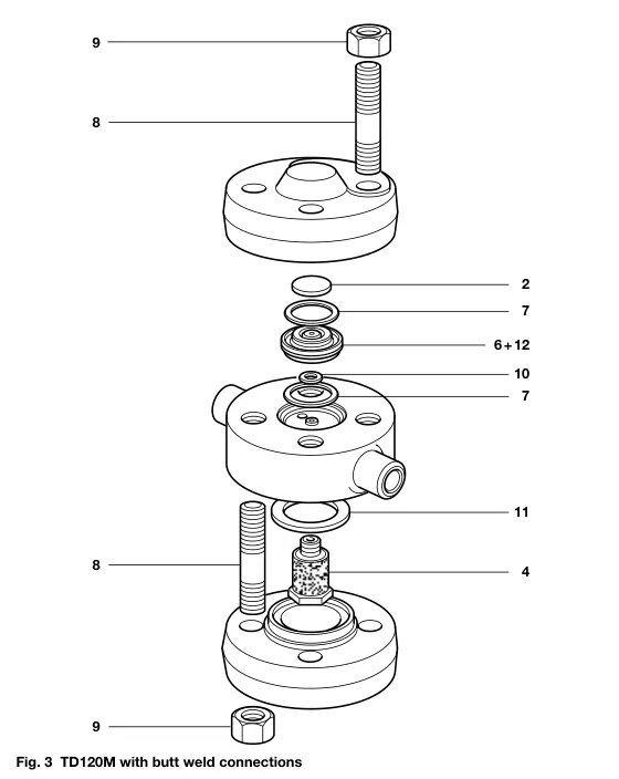
Table 1. Recommended tightening torques
| Item | Part / tool | N m | lbf ft |
|---|---|---|---|
| 4 | 22 A/F | 25–35 | 18–26 |
| 8 | Stud, M16 | 85–90 | 62.5–66 |
| 9 | Nut, 23 A/F, M16 | 160–180 | 118–132 |
7. Spare parts
The available spare parts are shown in solid outline in the source illustration. Parts drawn in a broken or grey line are not supplied as spares.
| Available spare | Items |
|---|---|
| Set of cover studs and nuts | 8 (8 off), 9 (8 off) |
| Strainer screen and gasket | 4, 11 |
| Set of gaskets | 7 (2 off), 10, 11 |
| Maintenance kit | 2, 4, 7 (2 off), 10, 11, 6 + 12 |
How to order spares
Order spares using the description in the Available spares table and state the size and type of trap. Example: one seat and disc assembly for a 1/2 inch TD120M high-pressure thermodynamic steam trap.
Technical information
| Document | Reference | Language | Download |
|---|---|---|---|
| TD120M High Pressure Thermodynamic Steam Trap with Replaceable Seat | TI-P150-11 | English | Download |
Installation and maintenance
| Document | Reference | Language | Download |
|---|---|---|---|
| TD120M Thermodynamic Steam Trap with Replaceable Seat - Installation and Maintenance Instructions | IM-P150-12 | English | Download |