
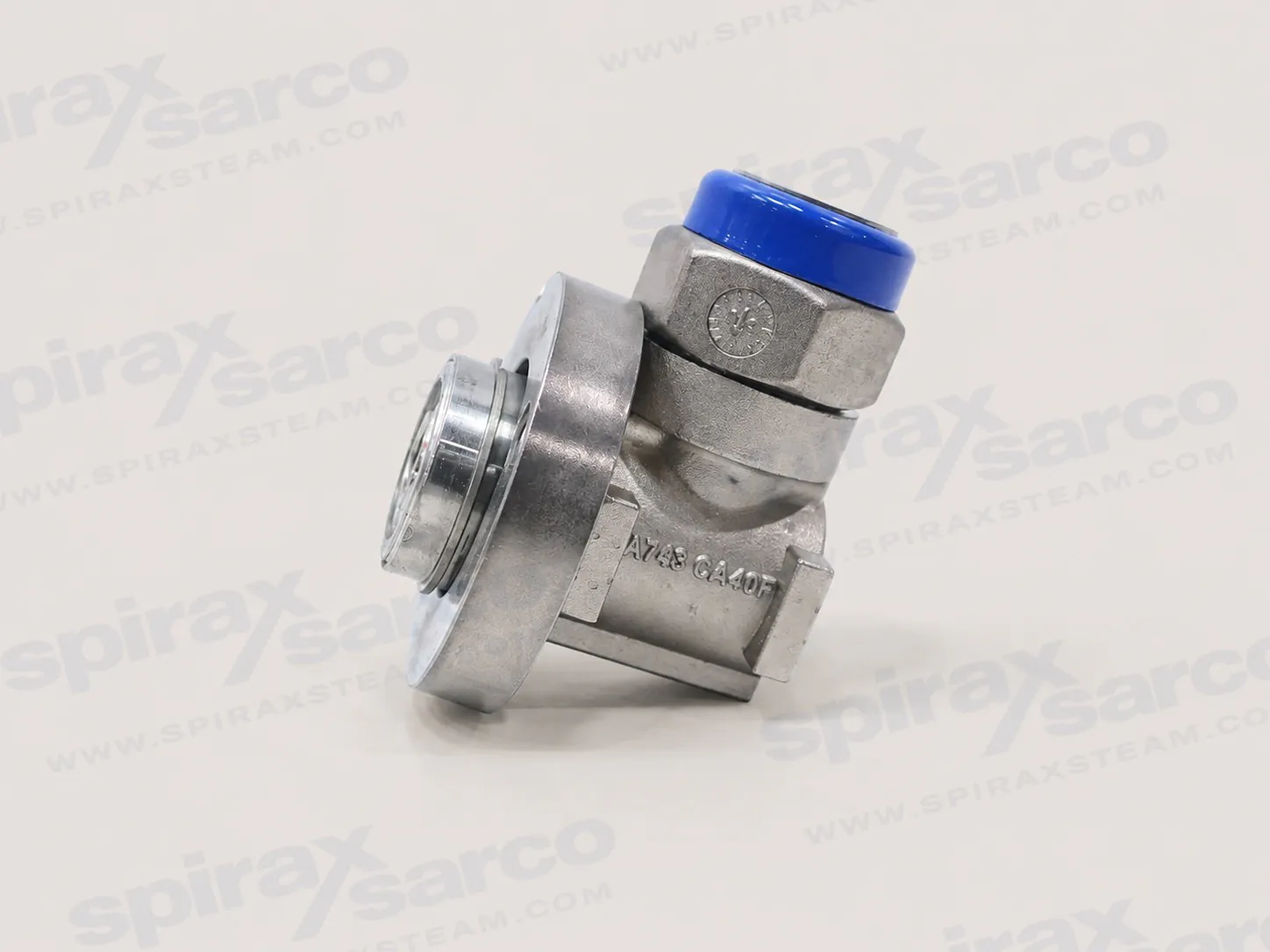
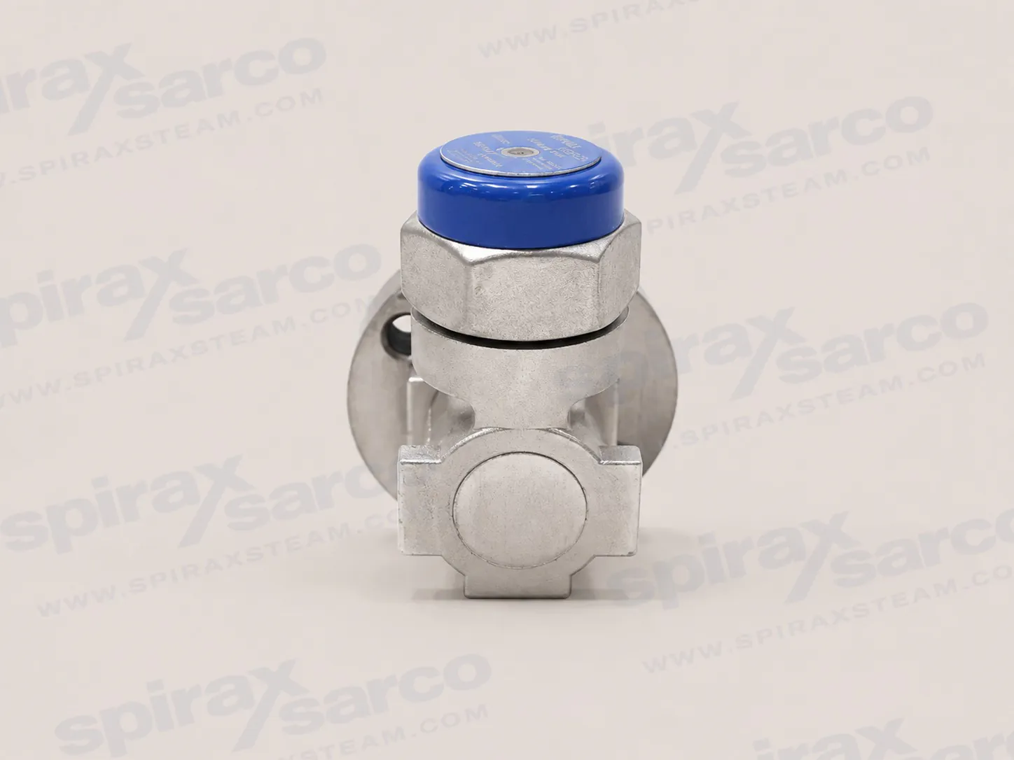
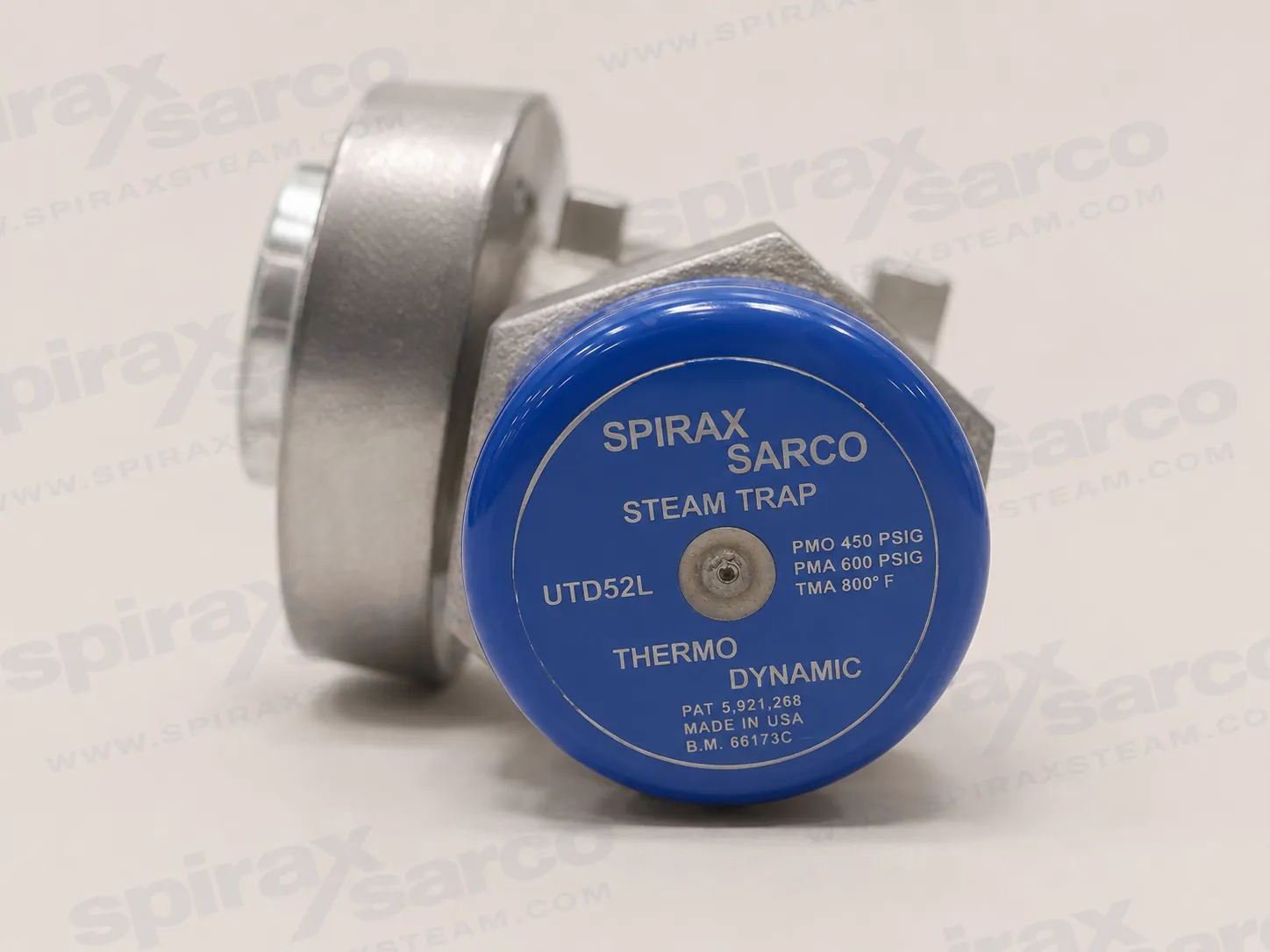
UTD52L
UTD52L Universal Thermodynamic Steam Trap
Spirax Sarco UTD52L is a stainless steel bar-stock universal thermodynamic steam trap for use with a separately selected connector in steam main drainage, steam tracing and constant-load duties.
UTD52L for universal connector installations
The UTD52L is a bar-stock universal thermodynamic steam trap designed to work with a separately selected universal connector. The connector remains in the pipeline while the trap can be removed for service or replacement, so the pipe joints do not have to be disturbed each time the trap is changed. The arrangement is intended for steam main drainage, steam tracing and constant-pressure or constant-load duties where a compact, positive-condensate discharge point is needed.
The Spirax Sarco UTD52L steam trap uses a stainless steel body and a slotted thermodynamic disc. Its universal connector arrangement helps keep the disc in the correct horizontal operating plane while allowing the trap body to be rotated for practical access and orientation. This gives the product a different installation and maintenance role from a conventional in-line threaded trap: the trap is the replaceable working unit, while the connector is the permanent pipework interface.
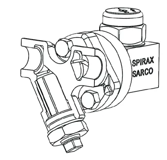
How the thermodynamic cycle works
The UTD52L has one moving working part: the disc. Condensate, air and other non-condensable gases enter through the inlet orifice and lift the disc so they can leave through the outlet passages. As hot condensate approaches steam temperature, a portion flashes to steam. The high-velocity flash steam gathers above the disc and raises the pressure in the control chamber. The resulting pressure imbalance presses the disc down onto the seating surfaces.
When cooler incoming condensate removes heat from the control chamber, its pressure falls. Inlet pressure can then lift the disc and the discharge cycle starts again. The result is periodic thermodynamic operation with discharge close to steam temperature and tight shut-off between discharges. The official installation guide notes that a clean cycle can normally be heard as the disc opens and closes; a rapid machine-gun-like cycle can indicate wear or dirt preventing the disc from seating correctly.
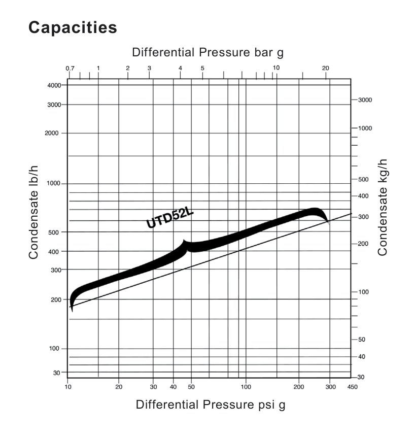
This operating principle is useful where a steam system needs a simple disc trap with a defined pressure envelope and a replaceable trap body. It does not remove the need for correct sizing, upstream and downstream isolation, safe discharge planning or routine inspection. The capacity curve and limiting conditions must be checked against the actual differential pressure and condensate load rather than using the nominal connector size as a substitute for sizing.
Why the Spirax Sarco UTD52L steam trap uses a universal connector
A universal connector separates the permanent pipework connection from the trap itself. The swivel connector and trap range provides the wider product context when related connector-based arrangements must be compared. Once the connector is installed, two connector bolts and the associated gaskets hold the trap to the connector flange. The trap can be taken off without cutting pipe, breaking threaded joints or removing the connector from the line. This is particularly useful when a trap is installed in a repeatable maintenance position or where plant access makes pipework disturbance expensive.
The connector can be selected in a straight or strainer arrangement. The technical information lists standard and left-hand strainer patterns, which are mirror-image arrangements for space and bolt-access decisions. A strainer connector can protect the trap with an integral Y-pattern strainer screen; a standard connector installation should instead be assessed with the required upstream strainer arrangement. The connector itself may be stainless steel or cast steel, and the technical sheet also lists carbon-steel connector options and a USTSII trap station as ordering routes. These are connector choices, not changes to the UTD52L trap body.
Before choosing the connector, confirm the line connection standard, pipe size, flow direction, available clearance and the position of the bolt heads. The connector face must be installed in a vertical plane, while the trap should be rotated into a horizontal working position with its cap uppermost. A full-flow isolation valve is required on each side of the connector so the trap can be safely removed later.
Operating envelope and application fit
For the standard UTD52L configuration, the maximum operating pressure is 450 psi g, equivalent to 31 bar g, and the maximum operating temperature is 750 F, or 400 C. The documented operating pressure range is 3.5 to 450 psi g, approximately 0.24 to 31 bar g. Maximum back pressure must not exceed 80% of the upstream pressure. These limits are operating boundaries, not a replacement for a complete system pressure assessment. The technical sheet separately gives the pressure-shell design condition and the maximum cold hydraulic test pressure; those values should not be confused with continuous operating limits.
The product is aimed at steam main drainage, steam tracing and constant-pressure or constant-load applications. In these duties, selection should consider the condensate load at start-up and during normal operation, the available differential pressure, the effect of back pressure, the steam temperature, and whether the discharge can be routed safely. A capacity curve is provided in the technical section so the actual differential pressure can be checked against the expected condensate duty.
The stainless steel trap construction and ceramic insulating element support use in hot steam service, but material compatibility remains a project responsibility. Confirm the steam quality, line materials, connection materials, local pressure rules and any requirements for a strainer or blowdown arrangement before ordering. The UTD52L is not a universal answer for every condensate point: where a project needs a fixed flanged connection instead, the separate TD32F flanged thermodynamic steam trap route should be assessed; a duty with a different pressure class, clean-steam requirements or unusual condensate behaviour needs a separate product decision.
For broader steam-trap selection, the verified steam trap selection range provides the comparison route. The UTD52L page should be used when the project specifically needs this universal thermodynamic trap and its connector-based maintenance arrangement, rather than treating the model as a generic replacement for every thermodynamic or mechanical trap.
Construction and engineering value
The exact UTD52L technical sheet identifies a stainless steel body, cap, disc and flange, a ceramic insulator, and stainless steel components with exfoliated graphite filler for the inner and outer gaskets. The connector screws are alloy steel, plated and specified to ASTM A193 Grade B7. The construction gives engineers a clear set of materials to review against the plant specification and makes the replacement unit identifiable when a connector remains in service.
The slotted disc and integral seat design are part of the thermodynamic trap assembly. The technical sample specification describes on/off discharge with tight shut-off and no bleed or controlled leak, with back pressure up to the stated fraction of inlet pressure. That wording is useful when preparing a procurement specification, but final performance still depends on correct differential pressure, clean seating surfaces, the connector condition and the installation instructions.
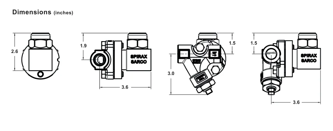
Dimensional drawings in the technical section show the trap and connector arrangement in inches. They should be used to check access, insulation clearance and removal space, not as a substitute for the manufacturer drawing review on a project with tight pipe-rack geometry. The illustrated connector options also show why standard and left-hand strainer patterns must be chosen before purchase: the orientation changes the side on which the trap body and connector bolts sit.
What to confirm before ordering
Confirm that the required product is UTD52L and that the page is not being used to specify a different UTD52 family model.
Confirm the universal connector size: 1/2 inch, 3/4 inch or 1 inch.
Confirm NPT or socket-weld connection requirements, including the applicable ANSI B16.11 requirement for socket welds.
Choose a straight or strainer connector and decide whether the standard or left-hand pattern is needed for the flow direction and available access.
Check the differential pressure, condensate load, 31 bar g pressure limit, 400 C temperature limit and 80% maximum back-pressure rule.
Provide full-flow isolation on both sides and allow the trap to be removed without unsafe access or hot work.
Confirm whether the connector needs an integral strainer, blowdown provision, carbon-steel construction or a station arrangement.
Check the technical drawing, gasket condition, bolt access, insulation clearance and the safe route for any discharge before the order is released.
When a Spirax Sarco UTD52L steam trap is ordered, the trap and connector should be treated as a coordinated selection. The trap model identifies the replaceable thermodynamic unit; the connector determines how the permanent pipe interface, strainer choice, orientation and maintenance access will work. Keeping those decisions together reduces the risk of receiving a correctly named trap that does not match the installed connector or the available space.
Description
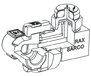
The thermodynamic steam trap cycles periodically to discharge condensate very near to steam temperature. It is unaffected by waterhammer or superheat. The UTD52L uses a universal connector arrangement to maintain the disc in the horizontal plane. The trap can be replaced or removed for servicing without disturbing the pipe connections.
Product data
Item | UTD52L |
|---|---|
Model | UTD52L |
PMO | 450 psi g (31 bar g), standard |
Trap construction | Stainless steel |
Trap option | Slotted disc |
Connector sizes | 1/2 inch, 3/4 inch and 1 inch |
Connector connections | NPT and socket weld |
Connector construction | Straight or strainer type, left or right hand; stainless steel or cast steel |
Connector options | Socket weld connections to ANSI B16.11, carbon steel connector and USTSII trap station |
Limiting operating conditions
Condition | Value |
|---|---|
Maximum operating pressure, PMO | 450 psi g (31 bar g), standard |
Maximum operating temperature, TMO | 750 F (400 C) |
Pressure range | 3.5 to 450 psi g UTD52L, approximately 0.24 to 31 bar g |
Maximum back pressure | Must not exceed 80% of upstream pressure |
Local regulations may restrict use below the quoted conditions. The limiting conditions refer to standard connections.
Pressure shell design conditions
Condition | Value |
|---|---|
Maximum allowable pressure, PMA | 450 psi g at 750 F; 31 bar g at 238-400 C, standard |
Maximum allowable temperature, TMA | 750 F at 0-450 psi g; 400 C at 0-31 bar g, standard |
Cold hydraulic test | Maximum 1080 psi g |
Typical applications
Steam main drainage, steam tracing, and constant-pressure or constant-load applications.
Materials
No. | Part | Material |
|---|---|---|
1 | Body | Stainless steel, ASTM A582 420F |
2 | Cap | Stainless steel, ASTM A743 Grade CA40 |
3 | Insulator | Ceramic |
4 | Cover/nameplate | As specified in the product assembly |
5 | Disc | Stainless steel |
6 | Flange | Stainless steel |
7 | Inner gasket | Stainless steel and exfoliated graphite filler |
8 | Outer gasket | Stainless steel and exfoliated graphite filler |
9 | Connector screws | Alloy steel, plated, ASTM A193 Grade B7 |
10 | Standard connector | Stainless steel, ASTM A351 Grade CF8 |
11 | Strainer connector | Stainless steel, ASTM A351 Grade CF8 |
12 | Strainer screen | 0.031 inch perforation |
13 | Strainer cap | Stainless steel, AISI 303 |
Consult the manufacturer for material specifications in carbon steel connectors. Connector and strainer items are options associated with the selected connector, not additional materials in the UTD52L trap body.
Capacity and dimensions
Sample specification
The steam trap shall be supplied with a pipeline connector which, once installed, remains in the line permanently. The trap shall be attached to the connector by two bolts to enable simple and rapid installation and replacement. The connection shall allow installation on pipework that is vertical, horizontal, or any angle in between. Operation shall be on/off discharge with tight shut-off and no bleed or controlled leak, with back pressures up to 80% of inlet pressure.
When specified, the connector shall be provided with an integral Y-pattern strainer with or without integral blowdown valve, in standard or left-hand pattern. The trap itself shall be a thermodynamic disc type of stainless steel construction with an integral seat design, hardened disc and seating surface. The cap shall have an integral ceramic insulator with a stainless steel cover.
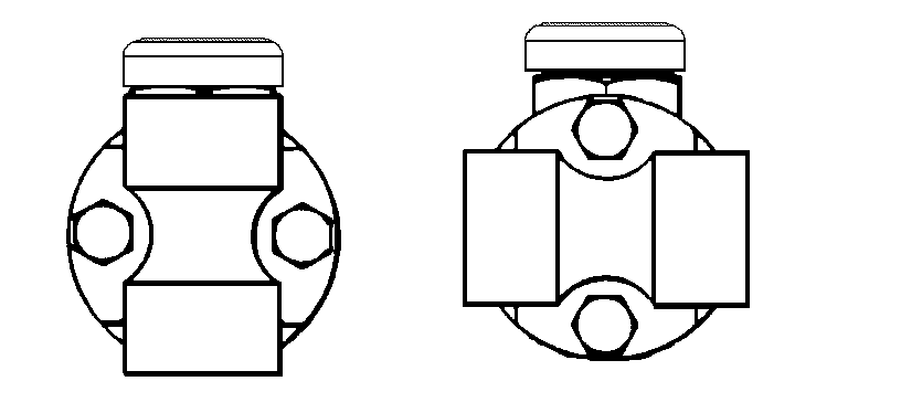
For location or space constraints, when facing the pipe in the direction of flow, the standard strainer connector places the trap body on the left with the bolt on the right. The left-hand connector places the trap body on the right with the bolts on the left.
Installation and maintenance summary
The connector can be installed in horizontal or vertical lines and its face must be in a vertical plane. Fit the trap to the connector with the cap uppermost. Install full-port isolating valves upstream and downstream. The trap can be removed for repair or replacement without disturbing the connector piping connections. Complete isolation of the connector from both supply and return is required before removal. Remove and disassemble the trap periodically for inspection and cleaning of the disc and seat. Complete instructions are given in IM-2-5161-US.
Spare parts
Spare part | Reference |
|---|---|
Connector screw and gasket set | A, B, C |
Disc | D |
Cap assembly | E |
Strainer screen | G |
Blowdown valve | H |
Strainer cap gasket | F |
Parts shown in heavy outline in the source drawing are available as spares. Parts drawn in broken line are not supplied as spares.
Installation and Maintenance Guide
Description and operation
Limiting operating conditions
Installation
Operation and troubleshooting
Maintenance
Description and operation
The UTD52L is a thermodynamic disc-type steam trap. It cycles open and closed to discharge condensate close to steam temperature and closes tightly between discharges. The disc is the only moving part. Cool condensate, air and other non-condensible gases enter through the central orifice, lift the disc and leave through the outlet orifices.
When condensate approaches steam temperature, part of it flashes as it enters the trap. Flash steam passes at high velocity over the underside of the disc and collects in the control chamber above. The pressure imbalance forces the disc down onto the seating surfaces and stops the flow. The trap remains closed until heat loss from cooler incoming condensate lowers the control chamber pressure, allowing inlet pressure to raise the disc and repeat the cycle.
The connector is permanently installed in the pipeline, which may be at any angle. The trap can be rotated through 360 degrees to orient it correctly and can be removed for servicing or replacement. The UTD52L trap is supplied with gaskets fitted and two connector bolts as the replaceable trap part; the selected connector remains the pipework interface.
Limiting operating conditions
Condition | UTD52L |
|---|---|
Maximum operating pressure, PMO | 450 psig (31 barg), standard |
Maximum operating temperature | 750 F (400 C) |
Pressure range | 3.5 to 450 psig |
Maximum back pressure | Must not exceed 80% of upstream pressure |
Cold hydraulic test | 1080 psig (approximately 74 barg) |
Installation
Install full-flow isolating valves so the connector can be isolated from both supply and return line pressure.
Use a Y-pattern strainer to protect the trap. The strainer connector includes this strainer. If a standard connector is used, fit a strainer between the upstream isolating valve and the connector.
Install the pipeline connector with the mating flange face in a vertical plane and observe the flow direction shown by the arrow on the connector.
Before attaching the trap, confirm that the inner and outer gaskets are correctly positioned in their grooves. The trap is supplied with the gaskets in place.
Apply a suitable anti-seize compound to the two bolts and attach the trap loosely. Rotate the trap to a horizontal position with the cap uppermost.
Using a 9/16 inch socket, tighten the two bolts evenly to 22-26 ft-lb.
When a strainer connector is used in a vertical position, the blowdown valve must be rotated 180 degrees so that discharge is directed downward. Do not operate or service a blowdown arrangement without first confirming isolation and a safe discharge route.
The insulating cover may rotate without affecting trap operation. Do not hammer the insulating cover because the ceramic and cover can be damaged. The trap requires no priming before service.
Operation and troubleshooting
The trap normally cycles on and off. The cycle rate depends on the condensate load and ambient conditions and may vary from less than one cycle per minute to one cycle every few seconds. A clear click as the disc cycles open and closed normally indicates operation.
If the disc is rapid cycling or machine-gunning, the trap may be worn or dirt or scale may be preventing the disc from seating. A downstream connection can be opened only under an appropriate site procedure to observe discharge. Because condensate is discharged close to steam temperature, some of it re-evaporates or flashes as it leaves the trap. The discharge is therefore a high-velocity mixture of flash steam and liquid condensate and may be mistaken for live steam. Condensate remaining in the outlet passages may also re-evaporate after closure.
Maintenance
Isolate the connector from both supply and return line pressure before any maintenance or trap removal. If a blowdown valve or trap station is fitted, use it to depressurize. Without a blowdown valve, allow the unit to cool completely and open the blowdown arrangement in the external pipeline where the site procedure permits.
Never loosen or remove the cap while the trap is fitted to the pipeline connector. If cap removal is necessary, carry it out in a workshop with the trap body secured in a vice. Unbolt the two connecting screws to remove the trap after the connector flange has been cleaned with a soft scraper.
The removed trap may be disassembled for inspection and cleaning. Use a smooth-jaw wrench on the cap flats only. Do not use a wrench on the insulating cover and do not use a pipe wrench, which can distort the cap and damage the body seating surfaces. Clean the disc and seating surfaces with a suitable solvent. A worn disc may be replaced; minor seat wear may sometimes be corrected by careful lapping on a perfectly flat lapping plate.
Install the disc with the grooved side down. Apply a small amount of high-temperature anti-seize compound to the cap threads and tighten the UTD52L cap to 70 ft-lb (95 Nm). If the trap is re-installed, use new gaskets. Remove old gaskets carefully, clean the spirally grooved gasket faces with a soft scraper, straighten the metal lips as required, and stake the new gaskets into position. Re-install the trap on the connector using the installation sequence above.