
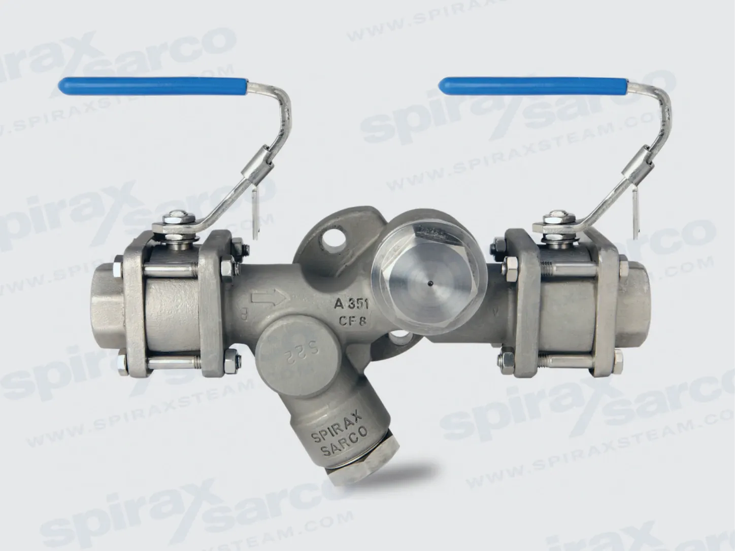
Compact steam trapping station for pipeline service
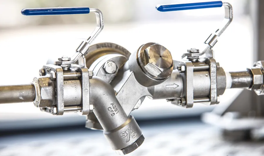
Spirax Sarco STS17.2 is a stainless steel compact pipeline connector steam trapping station supplied as a ready-to-install assembly for steam and condensate systems. It brings the main components of a trapping point together in one pre-assembled unit: upstream and downstream isolation valves, a body with an integral Quick-Fit connector and strainer, and a check-valve blanking plug. The result is a defined installation point for a separately selected swivel-connector steam trap, with less site fabrication and a clear route for future trap maintenance.
The station is intended for engineers who need to select the isolation arrangement, connection standard, trap type and discharge arrangement as one coordinated duty. It is not itself a standalone steam trap and it does not provide a capacity value simply from its nominal connection size. The final selection must be checked against condensate load, steam pressure, temperature, differential pressure, return-line backpressure, installation direction and the requirements of the connected plant.
Pre-assembled architecture with a maintainable connection
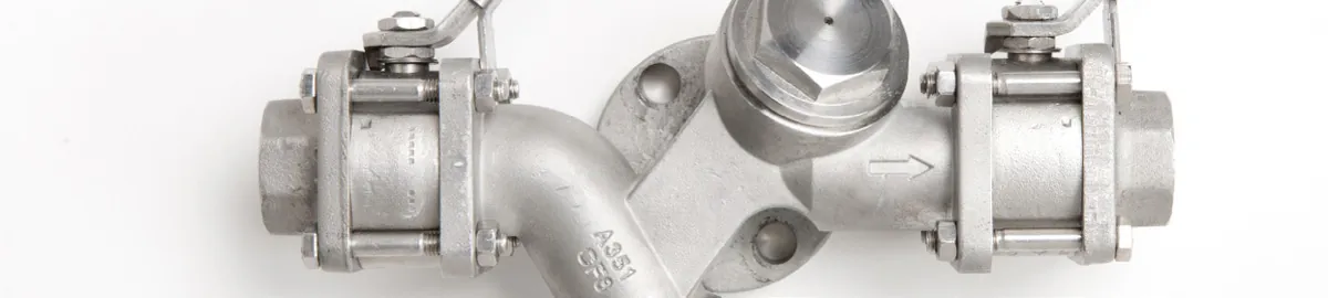
The one-piece stainless steel body reduces the amount of on-site assembly required around the trap connection. The integral strainer helps protect the trapping point from debris in the connecting line, while the removable strainer cap provides a defined maintenance access point. The Quick-Fit connector uses two bolts so that a compatible trap can be removed and refitted without rebuilding a conventional multi-valve trap station. This supports shorter maintenance interventions, provided the pipeline is isolated, safely vented and cooled before work starts.
Lockable handles are supplied as a standard feature in the product information. They help reduce the risk of accidental or unauthorised operation of the isolation valves. The all-stainless construction is also suited to projects that value corrosion resistance and cleanliness, although material compatibility and the actual plant environment must still be reviewed for every application.
Choose the isolation arrangement inside one STS17.2 model
The station is available in three documented isolation arrangements. Single Isolation (SB) provides one isolation valve. Double Isolation Upstream (DB) adds a second upstream isolation valve where the project requires enhanced isolation or a more controlled maintenance boundary. Double Block and Bleed (DBB) adds a T-shaped connection so steam trapped between the isolation valves can be drained. DBB is available with the upstream and downstream orientation codes documented in the technical information: USH for upstream horizontal, USV for upstream vertical, and DSH for downstream horizontal.
These codes are configuration choices within STS17.2, not separate products. A project should choose them from the required isolation procedure, available space and pipe direction. The technical tables that follow retain the separate approximate dimensions and weights for SB, DB, DBB USH, DBB USH DSH, DBB USV and DBB USV DSH. This distinction matters when planning support, access to the trap connector and clearance for operating or locking the handles.
Match the connector to a separate steam trap
The Quick-Fit connector allows the station to be tailored to the duty by selecting a compatible swivel-connector trap separately. The current technical and installation documents list UTD26 and UTD52 thermodynamic steam traps, UBP32 balanced pressure steam trap, USM bimetallic steam trap, UFT32 ball float steam trap, and UIB30 or UIB30H inverted bucket steam traps. The correct choice depends on the condensate load, air removal requirement, pressure and temperature conditions, differential pressure and return system. For a wider review of the available steam trap selection options, use the related selection information before fixing the station configuration.
Because the station has an integral screen, it should not be confused with a separate line strainer. A separate pipeline strainer or filter may still be required elsewhere in the system, but its function and sizing are outside this STS17.2 page. The built-in screen is part of the station and is serviced through the strainer cap.
Monitoring, blowdown and heat-loss options
Optional integral monitoring can be specified with an SSL1 sensor for steam-only indication or a WLSL1 sensor for waterlogging, used with the associated Spiratec indicator system described in the source documents. These sensors must not be fitted when the station is installed in a vertical application. This is a selection restriction, not just an installation preference, so the orientation and monitoring requirement should be agreed before ordering.
BDV1 is available for cleaning the integral strainer during operation. Its discharge may be hot, and the technical information states that BDV1 cannot be used when a Spiratec sensor has been selected as part of the unit. An insulation jacket is also available to reduce heat loss and energy wastage. Where insulation is planned, confirm the required access for handles, the trap connector, the strainer cap and any blowdown or sensor arrangement. The source brochure uses older labels for some accessories; the current technical and installation terminology is used here.
Connections and operating envelope
STS17.2 is documented in 1/2 inch, 3/4 inch and 1 inch screwed BSP T Rp (ISO 7-1), NPT or socket-weld connections. Flanged alternatives include ASME 150, ASME 300 and DN15, DN20 or DN25 EN 1092 PN40. The body design condition is PN40. The maximum allowable pressure is 40 bar g at 120 °C, and the maximum allowable and operating temperature is 230 °C at 10 bar g. For saturated steam, the maximum operating pressure is 11.3 bar g with ASME 150 connections and 17.5 bar g with all other connections. The documented minimum allowable and operating temperature is -10 °C; lower operating temperatures require consultation.
These values are conditional pressure-temperature limits rather than independent targets. The pressure-temperature chart and the prohibited region in the technical information must be used together, and local regulations may restrict the usable range. The station is stated to be safe under full vacuum conditions. The 60 bar g value is the maximum cold hydraulic test pressure and must not be used as an operating-pressure rating.
Installation decisions that affect performance and safety
The station can be installed in a horizontal line or in a vertical line with flow downwards. Upward vertical flow is prohibited. Flow arrows on the station must follow the fluid direction, and the installed layout must leave enough access to fit the selected Quick-Fit trap after the station is in the pipeline. Correct pipe alignment is essential: severe misalignment or an incorrect pipe length can apply damaging loads to the assembly. Connecting pipework should be clean before installation because dirt can damage the isolation-valve seats.
Socket-weld versions require the end caps to be dismantled, PTFE seats removed, each end cap welded to the pipeline, and the seats replaced before reassembly. The installation guide provides additional welding guidance based on British Standards, but it explicitly says that this guidance is not a substitute for a site-appropriate weld procedure. A competent person must confirm the welding method, materials, dimensions, fit-up and temperature controls used on the project.
For a discharge to atmosphere, the discharge point must be safe and protected from hot fluid. Where a blowdown arrangement is used, a suitable steam diffuser for atmospheric discharge can be reviewed as part of the broader discharge design. The station itself does not remove the need for safe isolation, venting, temperature normalisation, protective clothing, suitable access and local disposal controls.
Specify the complete duty before ordering
A Spirax Sarco STS17.2 enquiry should state the station model, isolation quantity, upstream and downstream orientation where applicable, connection size, connection type, selected Quick-Fit trap, monitoring or blowdown options, insulation requirement and any certification or inspection requirement. The technical ordering code uses STS17.2 followed by connection size, connection type, isolation quantity and orientation codes. Other combinations or special additions require confirmation with the manufacturer.
Before purchase, verify the normal and maximum pressure, temperature, saturated-steam operating pressure for the selected connection, minimum temperature, pipe direction, condensate service and return-line conditions. Confirm that the trap is suitable for the duty and that there is clearance for installation and maintenance. Also plan how the strainer will be cleaned, whether a sensor restriction applies, and where any hot blowdown or condensate discharge will terminate.
Spirax Sarco STS17.2 is therefore best treated as a coordinated trapping station rather than a nominal-size fitting. Its value is the combination of pre-assembled isolation, integral filtration and Quick-Fit maintenance access in a compact stainless steel assembly. The detailed technical and installation sections below preserve the configuration tables, limits, ordering code, safety requirements and maintenance procedures needed to complete the engineering review.
STS17.2 selection summary
- Pre-assembled stainless steel pipeline connector steam trapping station with isolation valves, integral strainer and Quick-Fit trap connector.
- SB, DB and DBB isolation arrangements, with documented horizontal and downward-flow vertical configurations.
- 1/2 inch to 1 inch threaded or socket-weld connections, ASME 150/300 options, and DN15 to DN25 EN 1092 PN40 flanges.
- Compatible swivel-connector traps are selected separately from the documented UTD26, UTD52, UBP32, USM, UFT32, UIB30 and UIB30H range.
- Optional SSL1 or WLSL1 monitoring, BDV1 strainer blowdown and insulation jacket, subject to their stated restrictions.
- Pressure, temperature, direction of flow, access and discharge safety must be checked together before ordering.
Description
The STS17.2 compact pipeline connector steam trapping station is a ready-to-install trapping solution comprising upstream and downstream isolation valves, a body incorporating a Quick-Fit connector and strainer, and a check-valve blanking plug.
Available types
The STS17.2 is available in Single, Double and Double Block and Bleed variations:
| Type | Description | Orientation codes |
|---|---|---|
| SB | Single Isolation | Not applicable |
| DB US | Double Isolation Upstream | US |
| DBB USH | Double Block and Bleed Upstream Horizontal | USH |
| DBB USH DSH | Double Block and Bleed Upstream Horizontal, Downstream Horizontal | USH, DSH |
| DBB USV | Double Block and Bleed Upstream Vertical | USV |
| DBB USV DSH | Double Block and Bleed Upstream Vertical, Downstream Horizontal | USV, DSH |
The DBB variation provides enhanced safety and the possibility of draining steam trapped between the isolation valves by adding a T-shaped connection.
Quick-Fit connector and compatible traps
The STS17.2 trapping solution incorporates Quick-Fit technology for speedy trap maintenance. The following swivel-connector steam traps, sold separately, can be used with the pipeline connector:
- UTD26 and UTD52 thermodynamic steam traps.
- UBP32 balanced pressure steam trap.
- USM bimetallic steam trap.
- UFT32 ball float steam trap.
- UIB30 and UIB30H inverted bucket steam traps.
Standards and certification
These products fully comply with the requirements of the European Pressure Equipment Directive 2014/68/EU.
Certification to EN 10204 3.1 is available. Certification and inspection requirements must be stated at the time of order placement. For other certification, contact Spirax Sarco.
Sizes and pipe connections
- 1/2 inch, 3/4 inch and 1 inch screwed BSP T Rp (ISO 7-1), NPT or socket weld.
- 1/2 inch, 3/4 inch and 1 inch ASME 150 and ASME 300.
- DN15, DN20 and DN25 flanged EN 1092 PN40.
Optional extras
- Integral SSL1 sensor for steam-only monitoring or WLSL1 sensor for waterlogging monitoring. SSL1 can be used with R1C; WLSL1 with diode can be used with RI6C. SSL1 and WLSL1 sensors must not be fitted when the STS17.2 is installed in a vertical application.
- BDV1 blowdown valve for cleaning the strainer during operation. The discharge may be hot, and BDV1 cannot be used when a Spiratec sensor has been selected as part of the unit.
- Retrofit double isolation valve and spool piece to convert a single upstream isolation version to double isolation.
- Insulation jacket to reduce heat loss and energy wastage.
Pressure and temperature limits
| Condition | Limit |
|---|---|
| Body design conditions | PN40 |
| PMA, maximum allowable pressure | 40 bar g at 120 °C (580 psi g at 248 °F) |
| TMA, maximum allowable temperature | 230 °C at 10 bar g (446 °F at 145 psi g) |
| Minimum allowable temperature | -10 °C (14 °F) |
| PMO, maximum operating pressure for saturated steam service, ASME 150 | 11.3 bar g (164 psi g) |
| PMO, maximum operating pressure for saturated steam service, all other connections | 17.5 bar g (254 psi g) |
| TMO, maximum operating temperature | 230 °C at 10 bar g (446 °F at 145 psi g) |
| Minimum operating temperature | -10 °C (14 °F). For lower operating temperatures consult Spirax Sarco. |
| Vacuum service | Safe for use under full vacuum conditions. |
| Cold hydraulic test pressure | Maximum 60 bar g (870 psi g). |
The product must not be used in the prohibited region of the pressure-temperature chart. Local regulations may restrict the use of this product to below the conditions quoted.
On the chart, region A-B represents screwed, socket weld, butt weld and flanged ANSI 300; region A-C represents flanged EN 1092 PN40; and region A-D represents flanged ASME Class 150 (ANSI 150). The chart scale is labelled from -10 °C (14 °F) to 230 °C (446 °F), including the 0 °C (32 °F) reference line.
Materials
Materials for the STS17.2 version with single isolation are listed below.
| No. | Part | Material |
|---|---|---|
| 1 | Body | Stainless steel, ASTM A351 Gr. CF8 |
| 2 | Isolation ball valves | Stainless steel, ASTM A182 F316L |
| 3 | Handle | Stainless steel, AISI 316 |
| 16 | Check-valve blanking plug | Stainless steel, ASTM A276 431 |
| 19 | Strainer cap | Stainless steel, ASTM A582 416 |
Dimensions and weights
Dimensions and weights are approximate. Dimensions are in mm (inches) and weights are in kg (lbs). Dimension B is 76 mm (3.0 inches), dimension C is 93 mm (3.7 inches), and dimension D is 90 mm (3.5 inches) for the SB and DB tables. The complete configuration tables are given below.
Single Isolation (SB)
| Size and connection | A | B | C | D | Weight |
|---|---|---|---|---|---|
| 1/2 inch BSP T Rp (ISO 7-1), 1/2 inch NPT and 1/2 inch SW | 222 (8.74) | 76 (3.0) | 93 (3.7) | 90 (3.5) | 3.60 (7.94) |
| 3/4 inch BSP T Rp (ISO 7-1) and 3/4 inch NPT | 222 (8.74) | 76 (3.0) | 93 (3.7) | 90 (3.5) | 3.53 (7.78) |
| 3/4 inch SW | 213 (8.39) | 76 (3.0) | 93 (3.7) | 90 (3.5) | 3.54 (7.80) |
| 1 inch BSP T Rp (ISO 7-1) and 1 inch NPT | 229 (9.02) | 76 (3.0) | 93 (3.7) | 90 (3.5) | 3.71 (8.18) |
| 1 inch SW | 269 (10.6) | 76 (3.0) | 93 (3.7) | 90 (3.5) | 3.86 (8.51) |
| 1/2 inch ASME 150 | 268 (10.55) | 76 (3.0) | 93 (3.7) | 90 (3.5) | 4.45 (9.81) |
| 1/2 inch ASME 300 | 294 (11.6) | 76 (3.0) | 93 (3.7) | 90 (3.5) | 4.98 (11.0) |
| DN15 EN 1092 PN40 | 284 (11.2) | 76 (3.0) | 93 (3.7) | 90 (3.5) | 5.12 (11.3) |
| 3/4 inch ASME 150 | 272 (10.7) | 76 (3.0) | 93 (3.7) | 90 (3.5) | 4.67 (10.3) |
| 3/4 inch ASME 300 | 306 (12.05) | 76 (3.0) | 93 (3.7) | 90 (3.5) | 5.98 (13.2) |
| DN20 EN 1092 PN40 | 304 (12.0) | 76 (3.0) | 93 (3.7) | 90 (3.5) | 5.74 (12.7) |
| 1 inch ASME 150 | 271 (10.67) | 76 (3.0) | 93 (3.7) | 90 (3.5) | 4.96 (10.9) |
| 1 inch ASME 300 | 309 (12.2) | 76 (3.0) | 93 (3.7) | 90 (3.5) | 6.64 (14.6) |
| DN25 EN 1092 PN40 | 304 (12.0) | 76 (3.0) | 93 (3.7) | 90 (3.5) | 6.24 (13.8) |
Double Isolation Upstream (DB US)
| Size and connection | A | B | C | D | Weight |
|---|---|---|---|---|---|
| 1/2 inch BSP T Rp (ISO 7-1), 1/2 inch NPT and 1/2 inch SW | 350 (13.8) | 76 (3.0) | 93 (3.7) | 90 (3.5) | 5.32 (11.7) |
| 3/4 inch BSP T Rp (ISO 7-1) and 3/4 inch NPT | 350 (13.8) | 76 (3.0) | 93 (3.7) | 90 (3.5) | 5.25 (11.57) |
| 3/4 inch SW | 341 (13.4) | 76 (3.0) | 93 (3.7) | 90 (3.5) | 5.26 (11.6) |
| 1 inch BSP T Rp (ISO 7-1) and 1 inch NPT | 357 (14.1) | 76 (3.0) | 93 (3.7) | 90 (3.5) | 5.43 (12.0) |
| 1 inch SW | 397 (15.63) | 76 (3.0) | 93 (3.7) | 90 (3.5) | 5.58 (12.3) |
| 1/2 inch ASME 150 | 396 (15.6) | 76 (3.0) | 93 (3.7) | 90 (3.5) | 6.17 (13.6) |
| 1/2 inch ASME 300 | 422 (16.6) | 76 (3.0) | 93 (3.7) | 90 (3.5) | 6.70 (14.8) |
| DN15 EN 1092 PN40 | 412 (16.2) | 76 (3.0) | 93 (3.7) | 90 (3.5) | 6.84 (15.1) |
| 3/4 inch ASME 150 | 400 (15.7) | 76 (3.0) | 93 (3.7) | 90 (3.5) | 6.39 (14.1) |
| 3/4 inch ASME 300 | 434 (17.1) | 76 (3.0) | 93 (3.7) | 90 (3.5) | 7.70 (17.0) |
| DN20 EN 1092 PN40 | 432 (17.0) | 76 (3.0) | 93 (3.7) | 90 (3.5) | 7.46 (16.4) |
| 1 inch ASME 150 | 399 (15.71) | 76 (3.0) | 93 (3.7) | 90 (3.5) | 6.68 (14.7) |
| 1 inch ASME 300 | 437 (17.2) | 76 (3.0) | 93 (3.7) | 90 (3.5) | 8.36 (18.4) |
| DN25 EN 1092 PN40 | 432 (17.0) | 76 (3.0) | 93 (3.7) | 90 (3.5) | 7.97 (17.6) |
Double Block and Bleed Upstream Horizontal (DBB USH)
| Size and connection | A | B | C | D | Weight |
|---|---|---|---|---|---|
| 1/2 inch BSP T Rp (ISO 7-1) | 351 (13.8) | 118 (4.65) | 93 (3.7) | 90 (3.5) | 6.37 (14.0) |
| 1/2 inch NPT | 351 (13.8) | 118 (4.65) | 93 (3.7) | 90 (3.5) | 6.37 (14.0) |
| 1/2 inch SW | 342 (13.5) | 118 (4.65) | 93 (3.7) | 90 (3.5) | 6.67 (14.7) |
| 1/2 inch ASME 150 | 397 (15.6) | 141 (5.55) | 93 (3.7) | 90 (3.5) | 9.77 (21.5) |
| 1/2 inch ASME 300 | 423 (16.7) | 154 (6.06) | 93 (3.7) | 90 (3.5) | 10.9 (24.0) |
| 1/2 inch PN40 | 413 (16.3) | 149 (5.87) | 93 (3.7) | 90 (3.5) | 11.04 (24.3) |
| 3/4 inch BSP T Rp (ISO 7-1) | 351 (13.8) | 118 (4.65) | 93 (3.7) | 90 (3.5) | 6.37 (14.0) |
| 3/4 inch NPT | 351 (13.8) | 118 (4.65) | 93 (3.7) | 90 (3.5) | 6.37 (14.0) |
| 3/4 inch SW | 342 (13.5) | 118 (4.65) | 93 (3.7) | 90 (3.5) | 6.67 (14.7) |
| 3/4 inch ASME 150 | 401 (15.8) | 143 (5.63) | 93 (3.7) | 90 (3.5) | 9.77 (21.5) |
| 3/4 inch ASME 300 | 435 (17.1) | 160 (6.30) | 93 (3.7) | 90 (3.5) | 10.9 (24.0) |
| 3/4 inch PN40 | 433 (17.0) | 159 (6.26) | 93 (3.7) | 90 (3.5) | 11.04 (24.3) |
| 1 inch BSP T Rp (ISO 7-1) | 358 (14.1) | 118 (4.65) | 93 (3.7) | 90 (3.5) | 6.52 (14.4) |
| 1 inch NPT | 358 (14.1) | 118 (4.65) | 93 (3.7) | 90 (3.5) | 6.52 (14.4) |
| 1 inch SW | 398 (14.1) | 138 (5.43) | 93 (3.7) | 90 (3.5) | 6.82 (15.0) |
| 1 inch ASME 150 | 400 (15.7) | 139 (5.47) | 93 (3.7) | 90 (3.5) | 10.07 (22.2) |
| 1 inch ASME 300 | 438 (17.2) | 158 (6.22) | 93 (3.7) | 90 (3.5) | 11.5 (25.4) |
| 1 inch PN40 | 433 (17.0) | 156 (6.14) | 93 (3.7) | 90 (3.5) | 11.64 (25.7) |
Double Block and Bleed Upstream Horizontal Downstream Horizontal (DBB USH DSH)
| Size and connection | A | B | C | D | Weight |
|---|---|---|---|---|---|
| 1/2 inch BSP T Rp (ISO 7-1) | 479 (18.9) | 118 (4.65) | 93 (3.7) | 90 (3.5) | 8.64 (19.0) |
| 1/2 inch NPT | 479 (18.9) | 118 (4.65) | 93 (3.7) | 90 (3.5) | 8.64 (19.0) |
| 1/2 inch SW | 470 (18.5) | 118 (4.65) | 93 (3.7) | 90 (3.5) | 9.04 (19.9) |
| 1/2 inch ASME 150 | 525 (20.7) | 141 (5.55) | 93 (3.7) | 90 (3.5) | 12.89 (28.42) |
| 1/2 inch ASME 300 | 551 (21.7) | 154 (6.06) | 93 (3.7) | 90 (3.5) | 14.22 (31.35) |
| 1/2 inch PN40 | 541 (21.3) | 149 (5.87) | 93 (3.7) | 90 (3.5) | 14.36 (31.66) |
| 3/4 inch BSP T Rp (ISO 7-1) | 479 (18.9) | 118 (4.65) | 93 (3.7) | 90 (3.5) | 8.64 (19.0) |
| 3/4 inch NPT | 479 (18.9) | 118 (4.65) | 93 (3.7) | 90 (3.5) | 8.64 (19.0) |
| 3/4 inch SW | 470 (18.5) | 118 (4.65) | 93 (3.7) | 90 (3.5) | 9.04 (19.9) |
| 3/4 inch ASME 150 | 529 (20.8) | 143 (5.63) | 93 (3.7) | 90 (3.5) | 12.89 (28.42) |
| 3/4 inch ASME 300 | 563 (22.2) | 160 (6.30) | 93 (3.7) | 90 (3.5) | 14.22 (31.79) |
| 3/4 inch PN40 | 561 (22.1) | 159 (6.26) | 93 (3.7) | 90 (3.5) | 14.36 (31.66) |
| 1 inch BSP T Rp (ISO 7-1) | 486 (19.1) | 118 (4.65) | 93 (3.7) | 90 (3.5) | 8.84 (19.5) |
| 1 inch NPT | 486 (19.1) | 118 (4.65) | 93 (3.7) | 90 (3.5) | 8.84 (19.5) |
| 1 inch SW | 526 (20.7) | 138 (5.43) | 93 (3.7) | 90 (3.5) | 9.24 (20.4) |
| 1 inch ASME 150 | 528 (20.8) | 139 (5.47) | 93 (3.7) | 90 (3.5) | 13.29 (29.3) |
| 1 inch ASME 300 | 566 (22.3) | 158 (6.22) | 93 (3.7) | 90 (3.5) | 15.02 (33.11) |
| 1 inch PN40 | 561 (22.1) | 156 (6.14) | 93 (3.7) | 90 (3.5) | 15.16 (33.42) |
Double Block and Bleed Upstream Vertical (DBB USV)
| Size and connection | A | B | C | D | Weight |
|---|---|---|---|---|---|
| 1/2 inch BSP T Rp (ISO 7-1) | 414 (16.3) | 106 (4.17) | 93 (3.7) | 90 (3.5) | 6.57 (14.5) |
| 1/2 inch NPT | 414 (16.3) | 106 (4.17) | 93 (3.7) | 90 (3.5) | 6.57 (14.5) |
| 1/2 inch SW | 411 (16.2) | 106 (4.17) | 93 (3.7) | 90 (3.5) | 6.87 (15.1) |
| 1/2 inch ASME 150 | 437 (17.2) | 129 (17.2) | 93 (3.7) | 90 (3.5) | 9.97 (22.0) |
| 1/2 inch ASME 300 | 450 (17.7) | 142 (5.59) | 93 (3.7) | 90 (3.5) | 11.1 (24.5) |
| 1/2 inch PN40 | 445 (17.5) | 137 (5.39) | 93 (3.7) | 90 (3.5) | 11.24 (24.8) |
| 3/4 inch BSP T Rp (ISO 7-1) | 414 (16.3) | 106 (4.17) | 93 (3.7) | 90 (3.5) | 6.57 (14.5) |
| 3/4 inch NPT | 414 (16.3) | 106 (4.17) | 93 (3.7) | 90 (3.5) | 6.57 (14.5) |
| 3/4 inch SW | 411 (16.2) | 106 (4.17) | 93 (3.7) | 90 (3.5) | 6.87 (15.1) |
| 3/4 inch ASME 150 | 439 (17.3) | 131 (5.16) | 93 (3.7) | 90 (3.5) | 9.97 (22.0) |
| 3/4 inch ASME 300 | 456 (18.0) | 148 (5.83) | 93 (3.7) | 90 (3.5) | 11.1 (5.83) |
| 3/4 inch PN40 | 455 (17.9) | 147 (5.79) | 93 (3.7) | 90 (3.5) | 11.24 (24.8) |
| 1 inch BSP T Rp (ISO 7-1) | 418 (16.5) | 106 (4.17) | 93 (3.7) | 90 (3.5) | 6.72 (14.8) |
| 1 inch NPT | 418 (16.5) | 106 (4.17) | 93 (3.7) | 90 (3.5) | 6.72 (14.8) |
| 1 inch SW | 438 (17.24) | 126 (4.96) | 93 (3.7) | 90 (3.5) | 7.02 (15.5) |
| 1 inch ASME 150 | 439 (17.3) | 127 (5.00) | 93 (3.7) | 90 (3.5) | 10.27 (22.64) |
| 1 inch ASME 300 | 458 (18.03) | 146 (5.75) | 93 (3.7) | 90 (3.5) | 11.7 (25.8) |
| 1 inch PN40 | 456 (18.0) | 144 (5.67) | 93 (3.7) | 90 (3.5) | 11.84 (26.10) |
Double Block and Bleed Upstream Vertical Downstream Horizontal (DBB USV DSH)
| Size and connection | A | B | C | D | Weight |
|---|---|---|---|---|---|
| 1/2 inch BSP T Rp (ISO 7-1) | 542 (21.3) | 118 (4.65) | 93 (3.7) | 90 (3.5) | 8.84 (19.5) |
| 1/2 inch NPT | 542 (21.3) | 118 (4.65) | 93 (3.7) | 90 (3.5) | 8.84 (19.5) |
| 1/2 inch SW | 538 (21.2) | 118 (4.65) | 93 (3.7) | 90 (3.5) | 9.24 (20.4) |
| 1/2 inch ASME 150 | 565 (22.2) | 141 (5.55) | 93 (3.7) | 90 (3.5) | 13.09 (28.86) |
| 1/2 inch ASME 300 | 578 (22.8) | 154 (6.06) | 93 (3.7) | 90 (3.5) | 14.42 (31.79) |
| 1/2 inch PN40 | 573 (22.6) | 149 (5.87) | 93 (3.7) | 90 (3.5) | 14.56 (32.10) |
| 3/4 inch BSP T Rp (ISO 7-1) | 542 (21.3) | 118 (4.65) | 93 (3.7) | 90 (3.5) | 8.84 (19.5) |
| 3/4 inch NPT | 542 (21.3) | 118 (4.65) | 93 (3.7) | 90 (3.5) | 8.84 (19.5) |
| 3/4 inch SW | 538 (21.2) | 118 (4.65) | 93 (3.7) | 90 (3.5) | 9.24 (20.4) |
| 3/4 inch ASME 150 | 567 (22.32) | 143 (5.63) | 93 (3.7) | 90 (3.5) | 13.09 (28.86) |
| 3/4 inch ASME 300 | 584 (23.0) | 160 (6.30) | 93 (3.7) | 90 (3.5) | 14.42 (31.79) |
| 3/4 inch PN40 | 583 (22.95) | 159 (6.26) | 93 (3.7) | 90 (3.5) | 14.56 (32.10) |
| 1 inch BSP T Rp (ISO 7-1) | 546 (21.5) | 118 (4.65) | 93 (3.7) | 90 (3.5) | 9.04 (19.9) |
| 1 inch NPT | 546 (21.5) | 118 (4.65) | 93 (3.7) | 90 (3.5) | 9.04 (19.9) |
| 1 inch SW | 566 (22.3) | 138 (5.43) | 93 (3.7) | 90 (3.5) | 9.44 (20.8) |
| 1 inch ASME 150 | 567 (22.32) | 139 (5.47) | 93 (3.7) | 90 (3.5) | 13.49 (29.74) |
| 1 inch ASME 300 | 586 (23.1) | 158 (6.22) | 93 (3.7) | 90 (3.5) | 15.22 (33.55) |
| 1 inch PN40 | 584 (23.0) | 156 (6.14) | 93 (3.7) | 90 (3.5) | 15.36 (33.86) |
Spare parts - Double Isolation conversion kit
The spare parts are available as indicated below. No other parts are supplied as spares.
| Available spare | Item |
|---|---|
| Isolation ball valve seat and stem seals | 8, 9 |
| Strainer screen and gasket | 21, 22 |
| SSL1 Spiratec sensor | 23 |
| WLSL1 diode waterlogging sensor | 24 |
| Spiratec retrofit kit; state whether an SSL1 or WLSL1 sensor is required | 20, 21 + 23 or 24 |
| Check-valve assembly | 17, 18 |
| Double isolation conversion kit, including spool piece and additional isolation valve | X |
| BDV1 blowdown valve retrofit kit | 20, 21 + 25 |
Always order spares using the description in the available-spares column and state the size and model number.
Spare parts - Double Block and Bleed conversion kit
The spare parts are available as indicated below. No other parts are supplied as spares.
| Available spare | Item |
|---|---|
| Isolation ball valve seat and stem seals | 8, 9 |
| Strainer screen and gasket | 21, 22 |
| SSL1 Spiratec sensor | 23 |
| WLSL1 diode waterlogging sensor | 24 |
| Spiratec retrofit kit; state whether an SSL1 or WLSL1 sensor is required | 20, 21 + 23 or 24 |
| Check-valve assembly | 17, 18 |
| Double Block and Bleed conversion kit, including spool piece, connectors, additional isolation valves and their bolts, studs, nuts | X |
| BDV1 blowdown valve retrofit kit | 20, 21 + 25 |
Always order spares using the description in the available-spares column and state the size and model number. An example is one spare Spiratec sensor and sensor gasket with WLSL1 diode waterlogging sensor for a 1/2 inch STS17.2 compact pipeline connector steam trapping station.
How to order
Example: one 1/2 inch screwed BSP T Rp (ISO 7-1) STS17.2 stainless steel pipeline compact connector steam trapping station having a Spiratec SSL1 sensor.
| Product description | Code or option |
|---|---|
| Product | STS17.2 - steam trapping station |
| Connection size | 1/2 inch, 3/4 inch or 1 inch |
| Connection type | BSP - BSP T Rp (ISO 7-1) threaded, both ends |
| Connection type | NPT - NPT threaded, both ends |
| Connection type | SW - socket weld, both ends |
| Connection type | ASME 150 - ASME B16.5 Class 150, both ends |
| Connection type | ASME 300 - ASME B16.5 Class 300, both ends |
| Connection type | PN40 - BS EN 1092-1, both ends |
| Isolation quantity | SB - Single Isolation |
| Isolation quantity | DB - Double Isolation |
| Isolation quantity | DBB - Double Block and Bleed |
| Upstream connection orientation | US - upstream, used only for DB |
| Upstream connection orientation | USH - upstream horizontal, used only for DBB |
| Upstream connection orientation | USV - upstream vertical, used only for DBB |
| Downstream connection orientation | DSH - downstream horizontal, used only for DBB |
The listed combinations are Spirax Sarco standard combinations. The downstream orientation cell is left blank when no downstream connection is intended. For any other combination or special item addition, contact Spirax Sarco.
Safety, installation and maintenance
For full details, see the Installation and Maintenance Instructions IM-P128-23 supplied with the product.
Installation and Maintenance Guide
- Safety information
- General product information
- Installation
- Commissioning
- Maintenance
- Spare parts
Document scope
This document applies to the STS17.2 stainless steel compact pipeline connector steam trapping station and its documented SB, DB and DBB configurations. Read the safety information before installation or maintenance. For detailed pressure, temperature, connection, material and dimension data, also refer to TI-P128-22.
1. Safety information
Safe operation of these products can only be guaranteed if they are properly installed, commissioned, used and maintained by qualified personnel in compliance with the operating instructions. General installation and safety instructions for pipeline and plant construction, and the proper use of tools and safety equipment, must also be complied with.
1.1 Intended use
Referring to the Installation and Maintenance Instructions, name-plate and Technical Information Sheet, check that the product is suitable for the intended use and application. The products comply with the requirements of the European Pressure Equipment Directive 2014/68/EU and carry the CE mark when so required. STS17.2 DN15 to DN25 falls within the Group 2 gases and Group 2 liquids SEP categories shown in the source document.
- The STS17.2 is specifically designed for use on steam and condensate in Group 2 of the Pressure Equipment Directive. For other fluids, contact Spirax Sarco to confirm suitability.
- Check material suitability, pressure and temperature, including maximum and minimum values. If the product operating limits are lower than the system limits, provide a safety device to prevent overpressure or overtemperature.
- Determine the correct installation situation and direction of fluid flow.
- Spirax Sarco products are not intended to withstand external stresses induced by the connected system. The installer must consider these stresses and take precautions to minimise them.
- Remove protection covers from all connections and protective film from name-plates where appropriate before installation on steam or other high-temperature applications.
1.2 Access
Ensure safe access and, if necessary, a suitably guarded working platform before attempting to work on the product. Arrange suitable lifting gear if required.
1.3 Lighting
Ensure adequate lighting, particularly where detailed or intricate work is required.
1.4 Hazardous liquids or gases in the pipeline
Consider what is in the pipeline or what may have been in it previously. Consider flammable materials, substances hazardous to health and extremes of temperature.
1.5 Hazardous environment around the product
Consider explosion risk areas, lack of oxygen such as tanks or pits, dangerous gases, extremes of temperature, hot surfaces, fire hazards during welding, excessive noise and moving machinery.
1.6 The system
Consider the effect on the complete system of the work proposed. Closing isolation valves or electrically isolating equipment must not put other parts of the system or personnel at risk. Dangers include isolating vents or protective devices and rendering controls or alarms ineffective. Open and close isolation valves gradually to avoid system shocks.
1.7 Pressure systems
Ensure that all pressure is isolated and safely vented to atmospheric pressure. Consider double isolation, Double Block and Bleed (DBB), and locking or labelling closed valves. Do not assume that the system has depressurised even when a pressure gauge indicates zero.
1.8 Temperature
Allow time for temperature to normalise after isolation to avoid burns. Valves fitted with PTFE seats must not be subjected to temperatures above 260 °C (500 °F), because toxic fumes may be given off above these temperatures. Avoid inhalation of fumes or skin contact.
1.9 Tools and consumables
Before starting work, ensure that suitable tools and consumables are available. Use only genuine Spirax Sarco replacement parts.
1.10 Protective clothing
Consider whether personnel in the vicinity require protective clothing against chemicals, high or low temperature, radiation, noise, falling objects, and hazards to the eyes and face.
1.11 Permits to work
All work must be carried out or supervised by a suitably competent person. Installation and operating personnel should be trained in the correct use of the product according to these instructions. Follow a formal permit-to-work system where one is in force. Where there is no such system, a responsible person should know what work is in progress and arrange an assistant whose primary responsibility is safety where necessary. Post warning notices if required.
1.12 Handling
Manual handling of large or heavy products may cause injury, particularly to the back. Assess the task, individual, load and working environment and use an appropriate method for lifting, pushing, pulling, carrying or supporting the product.
1.13 Residual hazards
In normal use the external surface may be very hot. At maximum permitted operating conditions the surface temperature of some products may reach 230 °C (446 °F). Many products are not self-draining, so take care when dismantling or removing the product and refer to the maintenance instructions.
1.14 Freezing
Protect products that are not self-draining against frost damage where they may be exposed to temperatures below freezing point.
1.15 Disposal
Unless otherwise stated in these instructions, this product is recyclable and no ecological hazard is anticipated with disposal when due care is taken. The product is fitted with PTFE seats, so special care is required to avoid health hazards associated with decomposition or burning of PTFE.
Consult current product compliance information and local recycling and disposal regulations. PTFE can only be disposed of by approved methods and not by incineration. Keep PTFE waste in a separate container, do not mix it with other rubbish, and consign it to a landfill site.
1.16 Returning products
When returning products to Spirax Sarco, provide written information about hazards and precautions required because of contamination residues or mechanical damage that may present a health, safety or environmental risk. Include health and safety data sheets for substances identified as hazardous or potentially hazardous.
2. General product information
2.1 Description
The STS17.2 compact pipeline connector steam trapping station is a ready-to-install trapping solution comprising upstream and downstream isolation valves, a body incorporating a Quick-Fit connector and strainer, and a check valve blanking plug.
Available types
The STS17.2 is available in Single, Double and Double Block and Bleed variations. The DBB variation provides enhanced safety and the possibility of draining steam trapped between the isolation valves by adding a T-shaped connection.
| Type | Description |
|---|---|
| SB | Single Isolation |
| DB US | Double Isolation Upstream |
| DBB USH | Double Block and Bleed Upstream Horizontal |
| DBB USH DSH | Double Block and Bleed Upstream Horizontal Downstream Horizontal |
| DBB USV | Double Block and Bleed Upstream Vertical |
| DBB USV DSH | Double Block and Bleed Upstream Vertical Downstream Horizontal |
Quick-Fit connector and compatible traps
The trapping solution incorporates Quick-Fit technology, which allows speedy trap maintenance. The following swivel-connector steam traps, sold separately, can be used with the pipeline connector:
- UTD26 and UTD52 thermodynamic steam traps.
- UBP32 balanced pressure steam trap.
- USM bimetallic steam trap.
- UFT32 ball float steam trap.
- UIB30 and UIB30H inverted bucket steam traps.
Standards and certification
These products fully comply with the requirements of the European Pressure Equipment Directive 2014/68/EU. Certification to EN 10204 3.1 is available. State all certification and inspection requirements at the time of order placement. For other certification, contact Spirax Sarco.
2.2 Sizes and pipe connections
- 1/2 inch, 3/4 inch and 1 inch screwed BSP T Rp (ISO 7-1), NPT or socket weld.
- 1/2 inch, 3/4 inch and 1 inch ASME 150 and ASME 300.
- DN15, DN20 and DN25 flanged EN 1092 PN40.
Optional extras
- Integral SSL1 sensor for steam-only monitoring or WLSL1 sensor for waterlogging monitoring. SSL1 can be used with R1C; WLSL1 with diode can be used with RI6C. These sensors must not be fitted when the STS17.2 is installed in a vertical application.
- BDV1 blowdown valve for cleaning the strainer during operation. The discharge may be hot, and BDV1 cannot be used when a Spiratec sensor has been selected as part of the unit.
- Retrofit double isolation valve and spool piece to convert a single upstream isolation version to double isolation.
- Insulation jacket to reduce heat loss and energy wastage.
- Different connections and sizes on request, for example 1/2 inch upstream BSP T Rp (ISO 7-1) and 1 inch downstream ASME 150.
2.3 Pressure and temperature limits
| Condition | Limit |
|---|---|
| System design conditions | PN40 |
| PMA, maximum allowable pressure | 40 bar g at 120 °C (580 psi g at 248 °F) |
| TMA, maximum allowable temperature | 230 °C at 10 bar g (446 °F at 145 psi g) |
| Minimum allowable temperature | -10 °C (14 °F) |
| PMO, maximum operating pressure for saturated steam service, ASME 150 | 11.3 bar g (163.8 psi g) |
| PMO, maximum operating pressure for saturated steam service, all other connections | 17.5 bar g (294 psi g) |
| TMO, maximum operating temperature | 230 °C at 10 bar g (446 °F at 145 psi g) |
| Minimum operating temperature | -10 °C (14 °F) |
| Vacuum service | Safe for use under full vacuum conditions. |
| Maximum cold hydraulic test pressure | 60 bar g (870 psi g). |
The station must not be used in the prohibited region of the pressure-temperature chart. The chart identifies the A-B region as flanged ASME Class 300, screwed and socket weld; A-C as flanged EN 1092 PN40; and A-D as flanged ASME Class 150.
3. Installation
Before carrying out installation, observe the Safety information in Section 1. Referring to these instructions, the name-plate and the Technical Information Sheet, check that the product is suitable for the intended installation.
- Check materials, pressure and temperature and their maximum values. If the product maximum operating limit is lower than the system limit, provide a safety device to prevent overpressurisation.
- Ensure that the directional arrows on the steam trapping station point in the same direction as fluid flow in the pipeline.
- Remove protection covers from connections and protective film from name-plates where appropriate before installation on steam or other high-temperature applications.
- Ensure sufficient access for fitting a steam trap to the connector after the trapping station has been installed in the pipeline.
- Avoid severe misalignment and the pulling effect of incorrect pipe length. Pay particular attention to correct pipe alignment so that the inlet pipework and valve are on the same axis.
- Remove dirt from connecting pipework before installation and maintain cleanliness during installation. Dirt can damage the seats within the isolation valves.
- For socket-weld versions, dismantle the end caps from the body, remove the PTFE seats, weld each end cap to the pipeline, replace the PTFE seats and reassemble.
- Select a Quick-Fit connector steam trap suitable for the application and fit it to the station using the guidance provided with the selected product.
3.9 Installation orientation
The STS17.2 can be installed in a horizontal line or in a vertical line with flow downwards. The STS17.2 must not be fitted in a vertical line with flow upwards. The optional Spiratec SSL1 and WLSL1 sensors must not be fitted when the STS17.2 is installed in a vertical application.
| Permitted arrangement | Requirement |
|---|---|
| Horizontal line | Permitted when the flow arrows follow fluid flow. |
| Vertical line | Permitted only with flow downwards. |
| Vertical line with upward flow | Prohibited. |
| SSL1 or WLSL1 in vertical application | Prohibited. |
3.10 Welding socket-weld variants into a pipeline
A universal weld procedure covering different national and international standards and practices is difficult to provide because welding procedure, welding conditions, consumable storage and consumable selection vary. The information below is advice based on British Standards for the essential requirements of welding socket-weld STS17.2 stations into a pipeline. It is guidance only and is not a substitute for a weld procedure.
3.10.1 Welding of an STS17.2 steam trap station
The guidance covers 1/2 inch, 3/4 inch and 1 inch socket-weld STS17.2 stations to 15 mm, 20 mm or 25 mm Schedule 40 pipe.
| Connection | STS17.2 wall thickness (mm) | STS17.2 outside diameter (mm) | Pipe wall thickness (mm) | Pipe outside diameter (mm) |
|---|---|---|---|---|
| 1/2 inch | 5.15 | 32.00 | 2.76 | 21.30 |
| 3/4 inch | 5.00 | 37.00 | 2.87 | 26.70 |
| 1 inch | 5.60 | 45.00 | 3.38 | 33.40 |
| Welding item | Guidance |
|---|---|
| Parent materials | Austenitic stainless steel with minimum tensile strength up to and including 485 N/mm2. |
| Specifications | ASTM A182 F316L for STS17.2; ASTM A106 Gr. B for pipe. |
| Material group | R, A1. |
| Joint type | Socket joint to BS 3799 Class 3000 lb. Pipe to BS 1600 Schedule 40. |
| Welding process and position | Manual Metal Arc (MMA); all positions, site welded. |
| Diametrical clearance and pipe insertion | Diametrical clearance 1.0 mm maximum; pipe insertion 1.5 mm approximately. |
| Filler material | Low C, 23% Cr, 12% Ni; BS 2926:1984 23-12 L BR. |
| Shielding gas or flux | Not applicable. |
| Preparation and cleaning | Socket as supplied and wire brushed. Pipe mechanically cut and wire brushed. |
| Additional information | See Section 3.7. Fit-up using tack welds. |
| Preheat | Required only when ambient temperature is below 5 °C (41 °F); then warm to touch. |
| Interpass temperature and post-weld heat treatment | Interpass temperature not applicable. No post-weld heat treatment required. |
| Completed weld | Use the source weld-preparation guidance: completed weld dimension 1.4t minimum; the indicated edge must not be completely melted away. |
| Reference | BS 2633:1987 Section 3.1 and Figure 9; BS 806:1990 Section 4, Clause 4.7.3. |
3.10.2 Fit the selected trap
Select a Quick-Fit connector steam trap suitable for the application and fit it to the STS17.2 using the guidance provided in the Installation and Maintenance Instructions supplied with that steam trap.
4. Commissioning
After installation, ensure that the system is fully functioning. Carry out tests on alarms or protective devices. Open isolating valves slowly and ensure that there are no leaks.
5. Maintenance
Before starting any maintenance programme, observe the Safety information in Section 1. All work must be carried out by a suitably competent person. Ensure suitable tools are available and use only Spirax Sarco replacement parts.
5.1 General maintenance
Some maintenance can be completed with the steam trap station in the pipeline once the safety procedures have been observed. It is recommended that new gaskets and spares are used whenever maintenance is undertaken. Use the correct tools and necessary protective equipment at all times. When maintenance is complete, open isolation valves slowly and check for leaks.
5.2 Recommended tightening torques for strainer-related parts
| Item | Tool or thread | Torque N m | Torque lbf ft |
|---|---|---|---|
| 19 | 32 A/F, M28 x ISP | 170 - 190 | 126 - 140 |
| 20 adaptor | 32 A/F, M28 x ISP | 170 - 190 | 126 - 140 |
| 23 | 19 A/F | 50 - 55 | 37 - 40 |
| 24 | 24 A/F | 50 - 55 | 37 - 40 |
| 25 | 24 A/F | Not applicable | Not applicable |
| 26 | 17 A/F | 22 - 25 | 16 - 18 |
5.3 How to replace the strainer screen
- Before starting maintenance, isolate the steam trap station from mains pressure on both the steam and condensate sides. Vent residual pressure safely to atmosphere and allow the station to cool.
- Remove the strainer cap (19) with sensor (23 or 24 if fitted), taking care not to damage WLSL1 cables, or remove the optional blowdown valve (25 and 26), and separate the cap from the strainer screen (22).
- After cleaning or replacing the strainer screen, place it in the recess of the strainer cap (19 or 20).
- Using a new cap gasket (21), replace the screen and cap in the body of the STS17.2 and loosely tighten so that the screen and gasket locate correctly.
- Tighten to the recommended torque in the table above.
- Ensure sensor cables are not twisted and are secure.
- Recommission the station and ensure there are no leaks.
5.4 How to blow down the strainer screen
This procedure applies to models fitted with a blowdown valve. Periodic blowdown removes most debris within the screen; larger debris may require removal of the complete screen as described in Section 5.3.
The BDV1 blowdown valve has an integral valve screw (26), which can be unscrewed with a 17 mm A/F spanner to blow down the screen. A lockset screw prevents the integral valve screw from disengaging from the valve body (25). A torque of 22 - 25 N m (16 - 17 lbf ft) is recommended for resealing the integral valve screw.
Warning: Take adequate safety precautions when opening a blowdown valve to atmosphere. For full technical details of BDV1, see IM-P600-02.
5.5 How to replace or clean the sensor
- Isolate the station from mains pressure on both the steam and condensate sides, vent residual pressure to atmosphere and allow it to cool.
- If a WLSL1 waterlogging sensor is fitted, disconnect its wiring at the terminal block. Remove sensor 23 or 24 from adaptor 20. This can be done in line if the adaptor is securely held.
- Clean the sensor insulation. If pitting has occurred, fit a new sensor.
- Clean or replace the strainer screen as appropriate.
- Replace the new or cleaned sensor 23 or 24 in adaptor 20, ensuring the gasket 21 and strainer screen 22 are centralised.
- Tighten to the recommended torque, reconnect the waterlogging sensor as described in IM-P087-34, and observe the vertical-application restriction for SSL1 and WLSL1.
5.6 How to replace the check valve
- Using a 32 mm A/F spanner, unscrew and remove the check-valve blanking plug (16).
- Use a long 20 mm A/F socket to unscrew the check valve assembly (17) from the body.
- Replace the check-valve assembly and tighten to 110 - 120 N m (81 - 88 lbf ft).
- Using a new gasket (18), replace the blanking plug (16) and tighten it to the recommended torque in the table.
5.7 Recommended tightening torques
| Item | Size or tool | Torque N m | Torque lbf ft |
|---|---|---|---|
| 5 and 11 | 1/2 inch and 3/4 inch: 13 mm | 5.4 - 8.1 | 4 - 6 |
| 5 and 11 | 1 inch: 14 mm | 10.8 - 13.5 | 8 - 10 |
| 12, 14 and 13, 15 | M6 | 15 - 17 | 11 - 12 |
| 16 | 32 A/F, M35 x 1.5 | 190 - 200 | 140 - 147 |
| 20 adaptor | 32 A/F, M28 x ISP | 170 - 190 | 126 - 140 |
| 23 | 19 A/F | 50 - 55 | 37 - 40 |
| 24 | 24 A/F | 50 - 55 | 37 - 40 |
| 25 | 24 A/F | Not applicable | Not applicable |
| 26 | 17 A/F | 22 - 25 | 16 - 18 |
One-quarter inch studs and nuts are used when the STS17.2 is flanged. The source torque table specifies M6 and 15 - 17 N m (11 - 12 lbf ft) for the relevant stud and nut items.
5.8 How to replace ball-valve spares
Maintenance can be carried out without removing the complete ball valve from the pipeline. Remove the two upper bolts and nuts (12 and 13), then loosen the lower two (14 and 15). The complete body assembly (2) can then be removed and replacement parts fitted.
Renewal of seats
- Remove the body as described above.
- With the body removed, remove the seats (8).
- Fit new seats by pushing them into the body recesses.
Renewal of stem seals
- Remove the body as described above.
- Remove nuts (5 and 11) and the Belleville washers (10).
- Replace the stem seals (9).
Reassembly
Reassemble in reverse order. Tighten the ball-valve bolts and nuts (12 and 13, and 14 and 15) to the recommended torques.
6. Conversion kits
A retrofit kit is available to convert a standard single-isolation STS17.2 to Double Isolation or Double Block and Bleed. Conversion kits include a straight or T-shaped spool piece and additional ball-valve parts.
- Remove bolts or studs and nuts (12 and 13), then remove the end cap (6).
- Attach spool piece 27 or 28 using the new bolts or studs supplied with the kit together with existing nuts (12 and 13, and 14 and 15). Tighten to the recommended torque.
- Loosely assemble the existing end cap (6) to the other end of the spool piece with the new nuts and existing bolts or studs, leaving enough gap to slide in the new ball valve and body assembly (2).
- Slide the new ball valve and body assembly between the spool piece and end cap, then tighten the bolts or studs and nuts to the recommended torque.
- For Double Block and Bleed conversion, repeat the relevant steps at the T-shaped end using the supplied end cap, bolts and studs.
- Fit the new handle or handles (3) to the spindle of the new ball-valve assembly. Ensure correct orientation, fit the washer and nut (4 and 5), and tighten firmly.
Conversion-kit torque table
| Item | Size or tool | Torque N m | Torque lbf ft |
|---|---|---|---|
| 5 | 1/2 inch and 3/4 inch: 13 mm | 5.4 - 8.1 | 4 - 6 |
| 5 | 1 inch: 14 mm | 10.8 - 13.5 | 8 - 10 |
| 12, 14 and 13, 15 | M6 | 15 - 17 | 11 - 12 |
One-quarter inch studs and nuts are used when the STS17.2 is flanged. The conversion diagrams identify X as the Double Isolation conversion kit.
7. Spare parts
The spare parts are available as indicated below. No other parts are supplied as spares.
| Available spare | Item or reference |
|---|---|
| Isolation ball-valve seat and stem seals | 8, 9 |
| Strainer screen and gasket | 21, 22 |
| Spare sensor and sensor gasket: SSL1 Spiratec sensor | 23 |
| Spare sensor and sensor gasket: WLSL1 diode waterlogging sensor | 24 |
| Spiratec retrofit kit; state whether SSL1 or WLSL1 is required | 20, 21 + 23 or 24 |
| Check-valve assembly | 17, 18 |
| Double Isolation conversion kit, including spool piece and additional isolation valve | X |
| Double Block and Bleed conversion kit, including spool piece, connectors, additional isolation valves and their bolts, studs and nuts | X |
| BDV1 blowdown-valve retrofit kit | 20, 21 + 25 |
How to order spares
Always order spares using the description given in the Available spares column and state the size and model number. Example: one spare Spiratec sensor and sensor gasket with WLSL1 diode waterlogging sensor for a 1/2 inch STS17.2 compact pipeline connector steam trapping station.