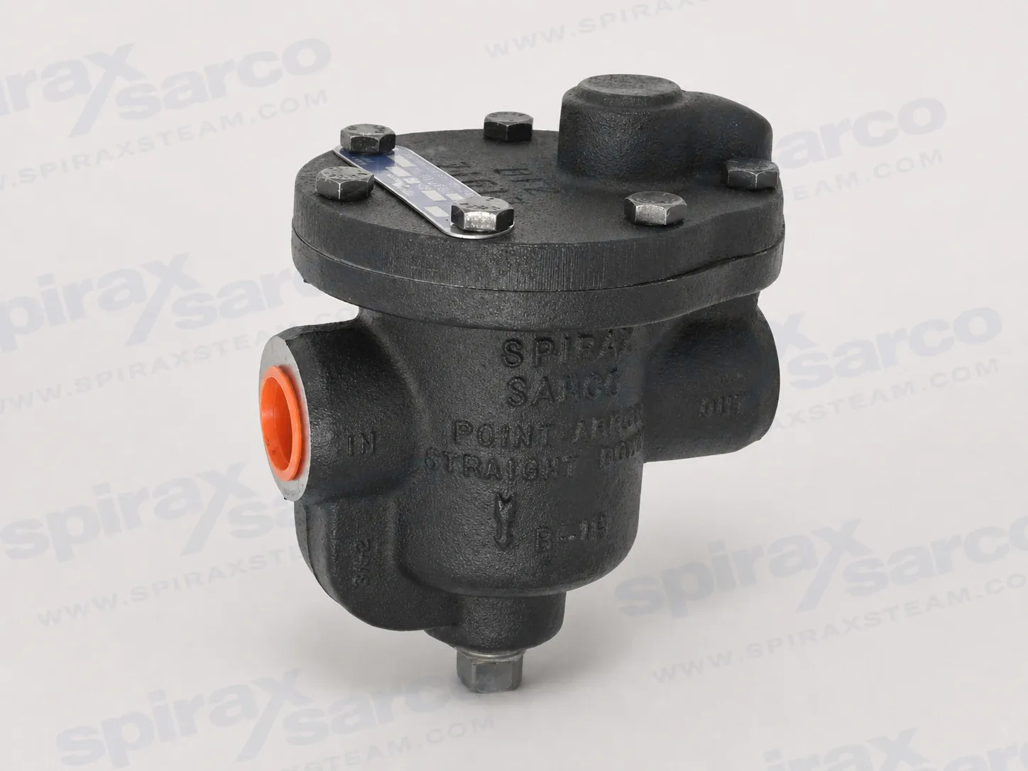
B1H is a maintainable cast iron inverted bucket steam trap for 1/2 inch and 3/4 inch screwed NPT connections, with stainless steel mechanism and bucket, optional air vent and strainer, and pressure-range selections up to 250 psig.
Genuine Spirax Sarco industrial steam productEngineered for energy efficiency and system safetyBacked by worldwide application engineering support
Quick facts
Model / CodeB1H
CategoryInverted bucket steam traps
ManufacturerSpirax Sarco
B1H inverted bucket steam trap for compact steam drainage
Spirax Sarco B1H is a cast iron inverted bucket steam trap for smaller steam and condensate drainage points. It is supplied in 1/2 inch and 3/4 inch sizes with screwed NPT connections. The trap uses a mechanical inverted bucket mechanism, stainless steel internal components and a cyclic discharge action to remove condensate close to steam temperature. That combination gives plant designers a compact, serviceable trap for steam main drip stations and equipment drainage where the available differential pressure and condensate load have been properly established.
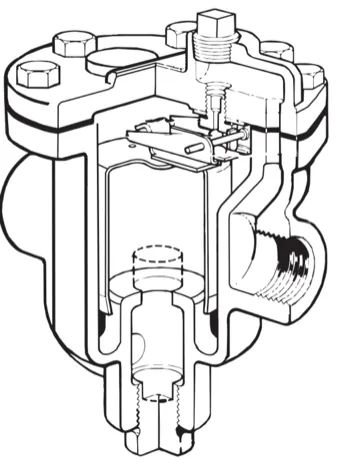
The B1H is a single product identity, while the technical capacity chart distinguishes pressure-range selections for the same trap family. A selection marked B1H-15, B1H-30, B1H-75, B1H-125, B1H-180 or B1H-250 is a pressure-range designation used for sizing and ordering; it must not be treated as a different base product page. The correct designation depends on both the maximum differential pressure and the capacity required at the minimum expected differential pressure.Cutaway view of the B1H construction. The inverted bucket and stainless steel operating mechanism work inside the cast iron body.
How the B1H works
An inverted bucket trap responds to the difference in density between steam and condensate. The bucket mechanism changes the valve position as the service condition changes, producing a cyclic discharge rather than a continuously open drain. The technical information sheet states that condensate is discharged close to steam temperature. This makes the product a mechanical steam trap intended to separate condensate drainage from the live steam supply while retaining the pressure and temperature limits of the selected pressure range.
That operating principle is useful at drainage points where water must be removed reliably but the trap must remain small and maintainable. It does not remove the need for engineering checks: the trap must have enough capacity at the lowest available differential pressure, must not be exposed to a differential pressure above its selected limit, and must be installed so the bucket can move in its intended vertical plane. For a broader explanation of trap families and application decisions, use the steam trap selection guidance alongside the model-specific data below.
Maintainable cast iron construction
The B1H body and cover are cast iron, identified in the technical information sheet as ASTM A126 Class B. The bucket, valve head, valve seat and bucket arm are stainless steel; the valve head and seat are specified as hardened stainless steel. A graphite cover gasket provides the cover seal. This combination is designed around a serviceable mechanical assembly rather than a sealed disposable cartridge. The trap can be isolated and inspected without disturbing the piping connections, provided the installation includes suitable isolation and the system has been made safe before work begins.
An integral strainer is available as an option for the B Series. It can help protect the valve head and seat from dirt and scale at the trap inlet, but it is not a reason to omit good upstream line protection. The installation guidance calls for a pipeline strainer ahead of the trap. Select and maintain pipeline strainers and filters according to the cleanliness and flushing requirements of the complete steam system.
A bimetal air vent is also available as an option. The technical sheet describes rapid air removal during cold start-up and states that the vent closes at approximately 200 °F (93 °C), remaining closed during normal trap operation. The option should be considered when air removal at start-up is important, but its effect on the installed height and service access must be included in the layout.
Typical applications and practical boundaries
Official B Series information identifies steam main drip stations, laundry equipment, industrial dryers and storage tanks as typical applications. In each case, the B1H should be selected as part of the drainage arrangement rather than by pipe size alone. A drip station may have a light but continuous condensate load; a dryer or storage tank may have a different start-up load and a changing pressure differential. The trap size, pressure-range designation, inlet condition, return pressure and drainage geometry should therefore be considered together.
The product is intended for steam service and for the condensate or water generated by that service. The installation instructions also discuss air service for the wider inverted bucket range. Any use with another fluid requires a separate suitability check based on material compatibility, pressure, temperature and the consequences of a malfunction. No assumption should be made from the name of the fluid alone, especially where hazardous, corrosive or oxygen-depleted conditions are possible.
For superheated steam or a return system in which condensate may be lifted, the piping arrangement needs additional protection. A check valve may be required after the trap to prevent backflow when condensate is elevated. For modulating pressure conditions or superheated steam, the installation guidance calls for a check valve at the trap inlet to help prevent loss of prime. Review the available steam check valves as part of the system design rather than adding a valve after the trap has already been selected.
Pressure, temperature and differential-pressure limits
The B1H technical sheet separates pressure-shell design limits from the operating limit selected by the orifice. The maximum allowable pressure is 250 psig up to 450 °F, equivalent to 17 barg up to 232 °C. The maximum allowable temperature is 450 °F (232 °C) over the stated 0–250 psig shell condition. The maximum operating temperature is also stated as 450 °F (232 °C) at all operating pressures. These are boundaries for engineering review; they are not permission to use every pressure-range selection at every combination of temperature and pressure.
For Spirax Sarco B1H, the maximum operating pressure, or PMO, is determined by the selected orifice. The capacity chart provides six B1H pressure ranges: 1–15 psig (0.07–1 bar), 5–30 psig (0.34–2 bar), 10–75 psig (0.69–5 bar), 20–125 psig (1.4–9 bar), 60–180 psig (4.1–12.4 bar) and 125–250 psig (9–17 bar). Choose a pressure range that safely covers the maximum differential pressure while still providing the required discharge capacity at the minimum differential pressure. If a trap is subjected to pressure above its selected maximum differential pressure, the capacity chart warns that it will not open.
The B1H pressure and temperature limits are useful for screening an application, but the real selection case should include the pressure at the trap inlet, the pressure in the return line, start-up conditions, possible backpressure, the minimum operating differential pressure and the temperature at the trap. If the system limits are higher than the trap limits, a different selection and a suitable safety device are required. Local regulations may also restrict operation below the conditions quoted in the manufacturer’s documentation.
B1H steam trap sizing by capacity
The capacity chart reports continuous condensate capacity in pounds per hour, with kilograms per hour obtained by multiplying the listed value by 0.454. The values are for condensate discharged at approximately steam temperature; cold-water discharge capacity is much higher and should not be substituted for the steam-condensate case. Start with the normal condensate load, apply a safety factor of two or three times that load according to the application, and then check the chart against the available differential-pressure range.
Oversizing deserves particular attention with bucket traps. The official chart warns that an oversized bucket trap, especially on a light-load application such as a main drip, can lose its prime and pass steam. Under-sizing can fail to remove the load at start-up or at the minimum pressure differential. A sound selection therefore checks the complete operating envelope: capacity at the minimum differential pressure, the maximum differential pressure allowed by the selected orifice, and the actual load profile rather than a nominal pipe diameter.
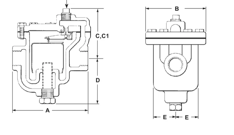
Both 1/2 inch and 3/4 inch B1H connections share the dimensions and weight shown in the technical sheet: approximately 5 inches (127 mm) across dimension A, 4 inches (102 mm) across B, 3.3 inches (84 mm) across C, 3 inches (76 mm) across D and 1.4 inches (36 mm) across E. The C1 dimension is 3.8 inches (97 mm) where the bimetal air-vent arrangement applies. Approximate weight is 6.2 lb (2.8 kg). These envelope values help with clearance and support planning, but the selected pressure range and options still need to be confirmed before ordering.
B1H steam trap installation and system integration
The B1H technical information sheet specifies a horizontal installation so that the inverted bucket can rise and fall vertically. The trap should be positioned below and close to the equipment drain point, with the flow direction verified from the casting and the connected piping. An upstream pipeline strainer protects the seat and head from debris, while full-port isolation valves around the trap allow service without disturbing the rest of the line. Unions or other removable connections should be considered where they improve safe access.
At start-up, the installation instructions require the inlet valve to be opened slowly, followed by the outlet valve, to establish a water seal or prime around the inverted bucket. If there is not enough condensate to prime the trap, the body may need to be filled manually after isolation and safe preparation. Repeated loss of prime can indicate that the trap is too large for the load, so changing to a smaller pressure/capacity selection may be more appropriate than repeatedly reopening the bypass.
When condensate is discharged to a raised return, fit the required non-return protection. If the trap is used with modulating pressure or superheated steam, include the inlet check-valve arrangement described in the installation instructions. Any bypass should have reduced capacity and should be positioned above the trap; it should be avoided unless continuous service is genuinely necessary. If discharge is routed to atmosphere, place the outlet where hot condensate and flash steam cannot endanger people or equipment.
Outdoor service also needs planning. The installation instructions state that a trap in continuous operation will not freeze, but it can be damaged if steam pressure is lost or turned off. Because the B1H is not presented as self-draining, provide manual drainage or an approved automatic frost-protection arrangement where freezing temperatures are possible.
B1H steam trap maintenance and ordering checks
Before any B1H maintenance, isolate the trap from both supply and return, safely vent pressure to atmosphere, allow the temperature to normalise and verify that the equipment cannot be re-pressurised. The maintenance sequence includes checking the inlet passage and optional strainer screen, inspecting the body and cover for corrosion, examining the hardened head and seat for wear or wiredrawing, confirming that the bucket vent hole is clear and replacing worn gaskets or mechanism parts as required. The separate installation information provides the complete service sequence and model-specific tightening torques.
Before ordering, confirm the 1/2 inch or 3/4 inch NPT connection, normal and maximum condensate load, minimum and maximum differential pressure, return-line backpressure, operating temperature, horizontal installation space and any requirement for the optional strainer or bimetal air vent. The pressure-range designation should be selected from the B1H capacity chart; it is not safe to infer it from the pipe size or from a nearby B Series model. With those checks complete, Spirax Sarco B1H provides a clear, maintainable inverted bucket steam trap option for compact steam drainage points within its documented limits.
Description
The B1H is a cast iron inverted bucket steam trap. Its mechanism responds to the difference in density between steam and condensate, and its discharge action is cyclic. Condensate is discharged close to steam temperature.
Sizes and connections
Model
Size
Connection
Installation pattern
B1H
1/2 inch and 3/4 inch
Screwed NPT
Horizontal
Typical applications
Steam main drip stations
Laundry equipment
Industrial dryers
Storage tanks
Construction and options
Part or feature
Material or information
Body
Cast iron, ASTM A126 Class B
Cover
Cast iron, ASTM A126 Class B
Cover screws
Steel, ASTM A449
Bucket
Stainless steel
Valve seat
Hardened stainless steel
Valve head (ball)
Hardened stainless steel
Valve lever (bucket arm)
Stainless steel
Cover gasket
Graphite
Optional bimetal air vent
Stainless steel; closes at approximately 200 °F (93 °C) during normal operation
Optional strainer screen
Stainless steel, 20 mesh
The bimetal air vent is intended to allow rapid air removal during cold start-up. The optional strainer helps protect the valve head and seat; a pipeline strainer should still be installed ahead of the trap.
Pressure shell design conditions
Designation
Description
Limit
PMA
Maximum allowable pressure
250 psig up to 450 °F (17 barg up to 232 °C)
TMA
Maximum allowable temperature
450 °F at 0–250 psig (232 °C at 0–17 barg)
Maximum operating temperature
At all operating pressures
450 °F (232 °C)
Limiting operating conditions
Designation
Condition
PMO
Maximum operating pressure is determined by the selected orifice. The documented pressure selections are 15 psig (1 bar g), 30 psig (2 bar g), 75 psig (5 bar g), 125 psig (9 bar g), 180 psig (12 bar g) and 250 psig (17 bar g).
Temperature
Maximum operating temperature at all operating pressures is 450 °F (232 °C).
Local regulations may restrict use below the quoted conditions. Always check the nameplate and the complete system pressure and temperature case.
Dimensions and weight
Approximate B1H dimensional drawing. Dimension C1 applies where the bimetal air-vent arrangement is supplied.
Size
Type
A
B
C
C1*
D
E
Weight
1/2 inch, 3/4 inch
B1H
5 in (127 mm)
4 in (102 mm)
3.3 in (84 mm)
3.8 in (97 mm)
3 in (76 mm)
1.4 in (36 mm)
6.2 lb (2.8 kg)
* C1 is the dimension for traps supplied with a bimetal air vent. Dimensions and weights are approximate.
Capacity and selection data
Capacities are in lb/hr. To convert to kg/hr, multiply lb/hr by 0.454. The chart values are maximum continuous discharge capacities for condensate at approximately steam temperature; cold-water discharge capacities are much higher. The source document is TI-P041-02-US.
When calculating the requirement, use a safety factor of two or three times the normal load according to the application. Select a pressure range that provides the required capacity at the minimum expected differential pressure and remains suitable for the maximum differential pressure. Oversizing, particularly on light-load main drips, can cause loss of prime and steam passage.
B1H-15 selection: 1–15 psig (0.07–1 bar g), 1/4 inch orifice
Differential pressure
Capacity lb/hr
1 psig (0.07 bar)
665
2 psig (0.14 bar)
715
3 psig (0.21 bar)
755
5 psig (0.34 bar)
835
10 psig (0.69 bar)
960
15 psig (1 bar)
1,040
B1H-30 selection: 5–30 psig (0.34–2 bar), 3/16 inch orifice
Differential pressure
Capacity lb/hr
5 psig (0.34 bar)
615
10 psig (0.69 bar)
715
15 psig (1 bar)
810
20 psig (1.4 bar)
895
25 psig (1.7 bar)
945
30 psig (2 bar)
1,000
B1H-75 selection: 10–75 psig (0.69–5 bar), 5/32 inch orifice
Differential pressure
Capacity lb/hr
10 psig (0.69 bar)
500
20 psig (1.4 bar)
610
30 psig (2 bar)
705
40 psig (2.8 bar)
770
60 psig (4.1 bar)
905
75 psig (5 bar)
965
B1H-125 selection: 20–125 psig (1.4–9 bar), 1/8 inch orifice
Differential pressure
Capacity lb/hr
20 psig (1.4 bar)
446
40 psig (2.8 bar)
600
60 psig (4.1 bar)
695
80 psig (5.5 bar)
765
100 psig (6.9 bar)
830
125 psig (9 bar)
920
B1H-180 selection: 60–180 psig (4.1–12.4 bar), 3/32 inch orifice
Differential pressure
Capacity lb/hr
60 psig (4.1 bar)
585
80 psig (5.5 bar)
642
100 psig (6.9 bar)
703
125 psig (9 bar)
765
150 psig (10 bar)
816
180 psig (12.4 bar)
867
B1H-250 selection: 125–250 psig (9–17 bar), 0.070 inch orifice
Differential pressure
Capacity lb/hr
125 psig (9 bar)
562
150 psig (10 bar)
600
175 psig (12 bar)
630
200 psig (13.8 bar)
665
225 psig (15.5 bar)
695
250 psig (17 bar)
720
Selection caution
The pressure-range designations above are selection variants of the B1H, not separate base products. The selected seat must be suitable for the maximum pressure differential and the trap must have enough capacity at the minimum expected differential pressure. A trap will not open if subjected to pressures greater than its maximum differential pressure.
1. Safety information
Safe operation can only be guaranteed when the B1H is installed, commissioned, used and maintained by qualified personnel in accordance with the operating instructions. General safety requirements for steam and condensate systems, tools and protective equipment also apply.
1.1 Intended use and system checks
Confirm from the nameplate and technical information that the B1H is suitable for the intended steam, air or water/condensate service. Suitability for other fluids requires confirmation based on material compatibility and the complete application.
Check the material, pressure and temperature limits, including the maximum and minimum values. If the trap limits are lower than the system limits, provide a suitable safety device against overpressure or overtemperature.
Confirm the installation position and flow direction. Remove protection covers from the connections before installation.
Consider external stresses from the connected pipework and take precautions to minimise them. Pipe misalignment and over-tightening can damage a cast iron product.
1.2 Access, environment and handling
Provide safe access and a guarded working platform where necessary. Arrange suitable lifting equipment if required. Provide adequate lighting and assess the contents of the pipeline, including flammable or hazardous substances and extreme temperatures. Consider explosion risks, lack of oxygen, dangerous gases, hot surfaces, welding, noise and moving machinery.
All work must be carried out or supervised by a suitably competent person. Installation and operating personnel should be trained in the correct use of the product. Follow any permit-to-work system and provide protective clothing appropriate to the hazards.
1.3 Pressure, temperature and freezing
Isolate pressure and safely vent the system to atmospheric pressure before work. Consider double isolation, locking or labelling closed valves, and never assume that the system is depressurised because a gauge reads zero. Allow temperature to normalise after isolation to avoid burns.
The external surface may be very hot in service; at maximum permitted operating conditions, the source instructions warn that some product surfaces may exceed 300 °C (572 °F). Many products are not self-draining, so protect the B1H from frost damage where temperatures can fall below freezing. If the cast iron trap is dropped and there is any risk of damage, do not use it unless it has been fully inspected and pressure tested by the manufacturer.
2. Preventing water hammer and pipe stress
Steam mains should be arranged with appropriate gradients and trap sets at suitable intervals so condensate does not collect in pockets. Good steam engineering practice is also required to prevent tensile stressing of the cast iron body. Support and guide the pipework so that the trap is not forced into alignment by the pipe joints, and tighten threaded connections with the correct torque rather than excessive force.
Where a trap is installed outdoors, remember that continuous steam operation does not by itself protect a non-self-draining body from freeze-up after steam pressure is lost or turned off. Provide a safe drain-down or an approved automatic frost-protection arrangement.
3. Installation
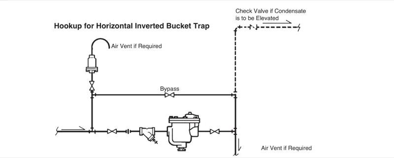
The B1H is the horizontal 1/2 inch or 3/4 inch NPT configuration of the B Series. Install it below and close to the equipment drain point, with the body arranged so that the inverted bucket can rise and fall vertically. The cast arrow or bottom marking must point downward and the flow direction must agree with the pipework.Horizontal inverted bucket trap hookup. The arrangement shows an upstream strainer, isolation valves, optional air vent, bypass and check-valve protection where condensate is elevated.
Before installation, blow down the inlet pipe carefully to remove existing debris. Before installation, inspection or maintenance, close the steam inlet and outlet valves and isolate the trap to protect personnel.
Check the maximum operating pressure stamped on the nameplate. If the actual system pressure is greater than the selected B1H pressure range, substitute a trap with a suitable higher operating-pressure selection.
Install the B1H in a horizontal position below the drain point, keeping the bucket movement vertical. Confirm that the body pattern, bottom marking and flow arrow are correctly oriented.
Fit a pipeline strainer ahead of the trap to protect the valve head and seat from dirt and scale. Fit suitable isolation valves around the trap and use pipe unions where they improve safe access for service.
To prevent backflow, fit a check valve after the trap when condensate is discharged to an elevated return. With modulating pressure conditions or superheated steam, also locate a check valve ahead of the trap inlet as required to help prevent loss of prime.
When draining equipment controlled by modulating valves with vacuum breakers, or where greater air-venting capability is required, fit an auxiliary thermostatic air vent in parallel above the trap.
If a bypass is necessary, install it above the trap and give it reduced capacity to reduce the chance of prime loss and steam loss. Avoid a bypass unless continuous service is genuinely required.
On start-up, open the inlet valve slowly and then the outlet valve to establish a prime or water seal around the inverted bucket. If there is not enough condensate to prime the trap, isolate it and pour water into the body manually. Repeated prime loss can indicate that the trap is oversized for the load.
For outdoor installations, manually drain the body after steam is lost or protect it with an automatic frost-protection arrangement. The installation instructions identify a Thermoton set with a 75 °F opening temperature as one possible arrangement.
4. Inspection and maintenance
Horizontal inverted bucket traps can be inspected and cleaned without removing the trap from the line. Complete isolation from both the supply and return line is required before servicing. Safely vent pressure, allow the trap to cool and confirm that it cannot be re-pressurised.
4.1 Operating inspection
Flash steam can form when hot condensate is discharged to a lower pressure. Do not confuse flash steam with live steam when inspecting trap operation.
To clean or inspect the inlet port, remove obstruction or debris from the inlet cavity. If the optional strainer is fitted, make sure its screen perforations are clear.
Inspect the body, cover, valve head, valve seat, operating mechanism and bucket vent hole at suitable intervals for the service. Replace worn or damaged parts with the appropriate complete mechanism assembly or genuine replacement parts.
4.2 Mechanism inspection and cleaning
Remove the cover bolts and cover.
Remove dirt and incrustation from the mechanism, body and cover. Inspect the body and cover for condensate corrosion.
Inspect the valve head and seat for damage, wear or wiredrawing. To remove the seat, detach the bucket arm by removing the pin and unscrew the seat.
Inspect the vent hole in the bucket and make sure it is clear and fully open.
Remove the old cover or body gasket and fit a new gasket.
Reinstall the cover and mechanism and tighten the cover bolts using the correct torque. Retightening the cover bolts after the trap has operated for a few hours is recommended to account for gasket relaxation and thermal expansion.
4.3 B1H tightening torques
Part
B1H size or configuration
Torque
Cover bolts
1/2 inch and 3/4 inch B1H
11–14 ft·lbf
Valve seat
1/2 inch and 3/4 inch B1H
28–31 ft·lbf
Traps with an optional strainer use the same cover-bolt and valve-seat torque requirements. Use the manufacturer’s complete instructions and the correct tools for the actual service work.
5. Disposal and return
Unless otherwise stated, the product is recyclable and no ecological hazard is anticipated when it is disposed of with due care. Follow local recycling and disposal regulations. When returning a product, provide written information about contamination residues, mechanical damage, hazards and the precautions required, including safety data sheets for hazardous substances where applicable.
Talk to our technical team
Contact Spirax Sarco for product selection, documentation or replacement guidance.