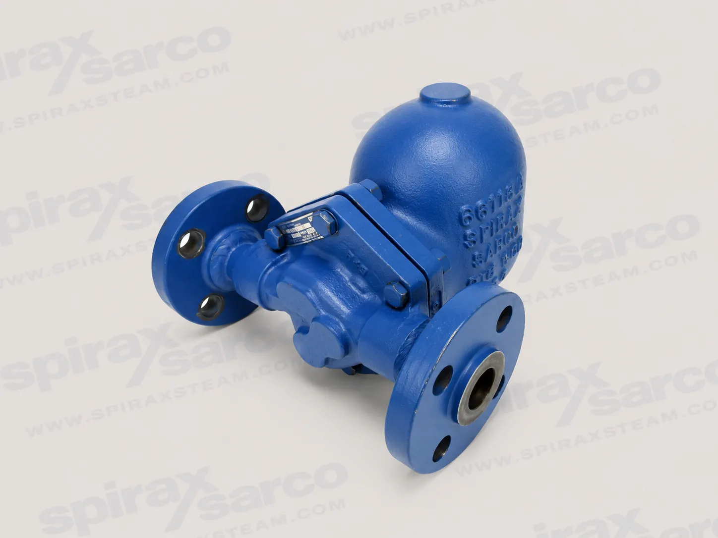
FT450 Float and Thermostatic Steam Trap
Cast steel float and thermostatic steam trap for continuous condensate removal, with internal air removal and size-specific pressure-temperature limits.

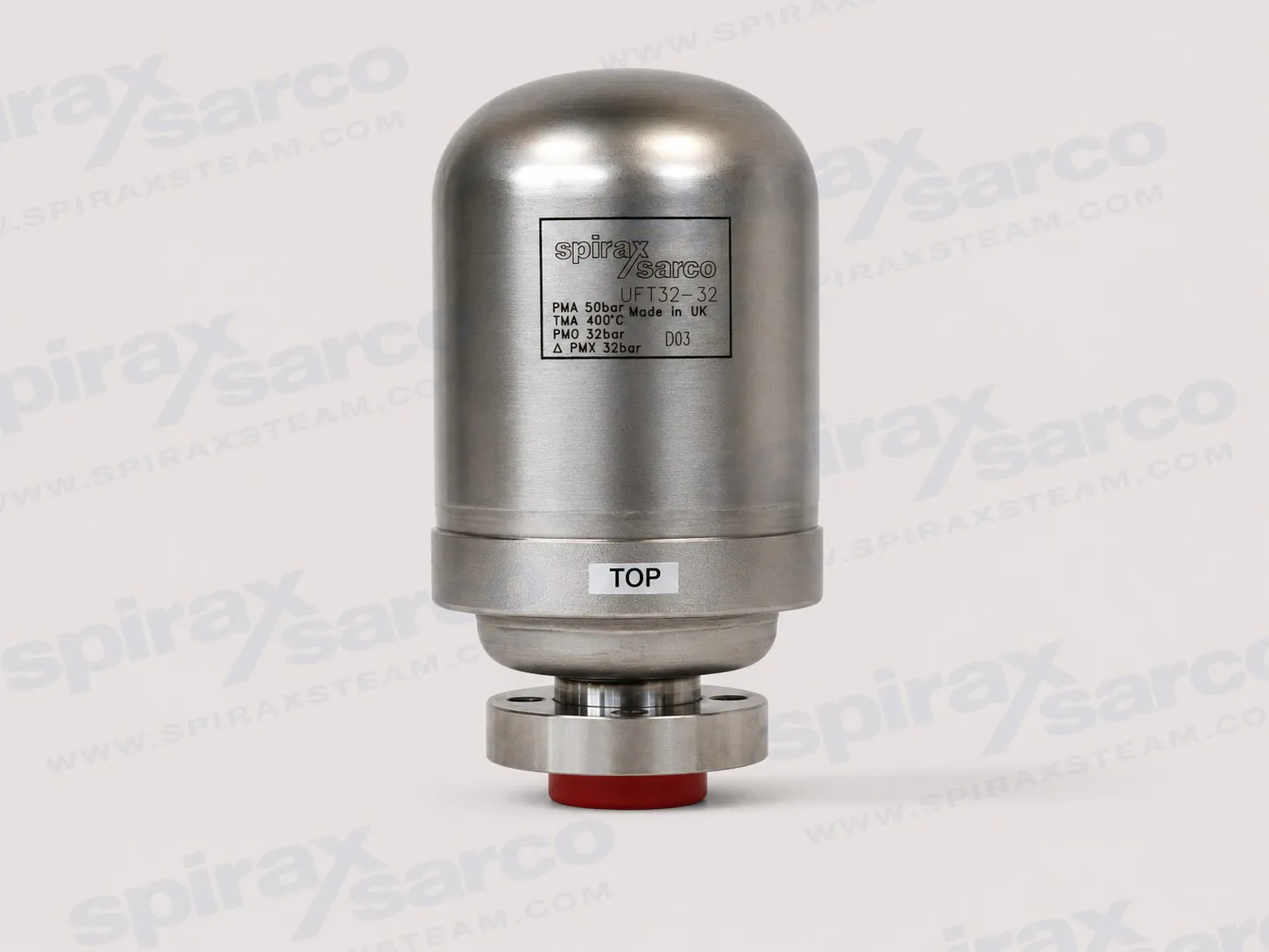
UFT32
Spirax Sarco UFT32 Sealed Ball Float Steam Trap
The Spirax Sarco UFT32 is a sealed stainless-steel ball float steam trap with integral automatic air venting and a connector-mounted design for differential steam pressures up to 32 bar.
The Spirax Sarco UFT32 is a sealed, maintenance-free austenitic stainless-steel ball float steam trap with an integral automatic air vent. Designed for differential steam pressures up to 32 bar, it combines continuous condensate drainage with a connector-mounted format that can shorten trap replacement time.
For engineers comparing a Spirax Sarco UFT32 steam trap with conventional in-line traps, the principal difference is its replaceable connector-mounted unit: the pipeline connector remains installed while the complete sealed trap is removed for replacement.
Ball float operation continuously discharges condensate as it forms, supporting stable heat-transfer duties.
The integral automatic air vent assists air removal during start-up and normal operation.
The sealed stainless-steel unit avoids internal overhaul; replacement is by complete trap unit.
A compatible universal pipeline connector allows the trap to be removed without cutting into the pipeline, helping reduce system downtime.
Use this model within a verified ball float steam trap application. Where maintenance standardisation is the priority, review the compatible swivel connectors and traps route as part of the installation design.
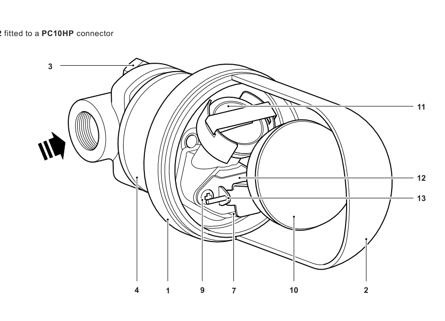
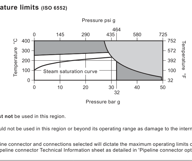
UFT32 is available in 4.5, 10, 14, 21 and 32 bar maximum differential-pressure ratings. The selected rating must suit the actual differential pressure; connector end connection, isolation arrangement and station configuration are selected separately. The product technical information states a maximum operating pressure of 32 bar g for saturated steam and a maximum operating temperature of 286°C at 29 bar g.
Before ordering, confirm the UFT32 pressure rating, compatible connector, process pressure and temperature, condensate load, connection standard and any EN 10204 3.1 certification requirement.
The UFT32 is an austenitic stainless-steel, sealed ball float steam trap with integral automatic air venting. The body-to-cover welded joint complies with ASME Section IX and BS/EN 288. The product complies with the European Pressure Equipment Directive 2014/68/EU and is available with EN 10204 3.1 certification when requested at order.
Connector | Configuration | Reference |
|---|---|---|
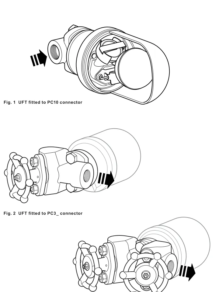
PC10HP | Straight connector, ASME 600 | TI-P128-10 |
PC20 | Straight connector with Y-type strainer, ASME 300 | TI-P128-15 |
IPC21 | Y-type strainer and integral Spiratec sensor, ASME 300 | TI-P128-15 |
PC3_ | One piston isolation valve, ASME 600 | TI-P128-02 |
PC4_ | Two piston isolation valves, ASME 600 | TI-P128-03 |
STS17.2 | Steam trap station | TI-P128-22 |
Body design condition | PN50 (ASME 300) |
|---|---|
Maximum allowable pressure | 50 bar g at 38°C |
Maximum allowable temperature | 400°C at 28 bar g |
Maximum operating pressure, saturated steam | 32 bar g |
Maximum operating temperature | 286°C at 29 bar g |
Minimum operating temperature | 0°C; consult Spirax Sarco for lower temperatures |
Cold hydraulic test pressure | 50 bar g |
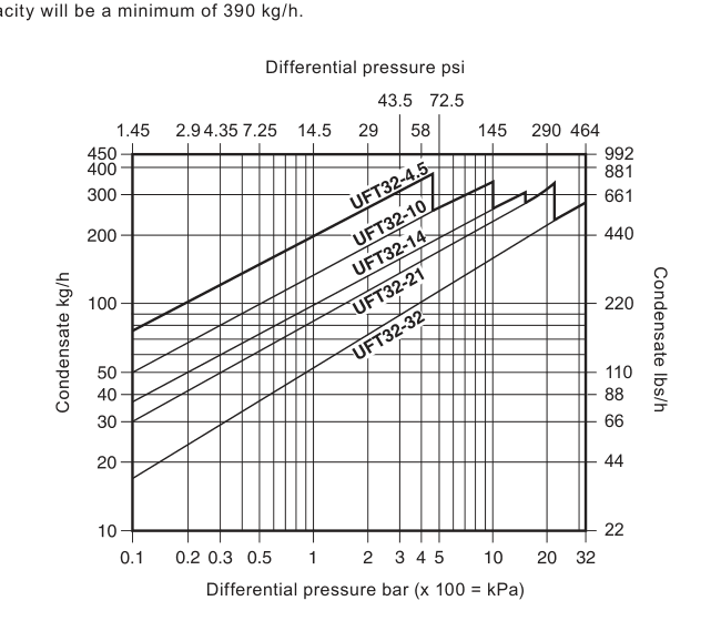
Rating | Maximum differential pressure |
|---|---|
UFT32-4.5 | 4.5 bar |
UFT32-10 | 10 bar |
UFT32-14 | 14 bar |
UFT32-21 | 21 bar |
UFT32-32 | 32 bar |
Part | Material | Standard |
|---|---|---|
Body | Austenitic stainless steel 304 | EN 10213-4 1.4308 / ASTM A351 CF8 |
Cover | Austenitic stainless steel 304 | EN 10028-7 1.4301 / ASTM A240 Gr. 304 |
Ball float and lever | Stainless steel | EN 10088-2 1.4301 |
Inlet and outlet gaskets | Graphite/stainless-steel laminate | — |
Approximate overall dimensions are A 168.5 mm, B 94 mm and C 47 mm; approximate mass is 2.02 kg.
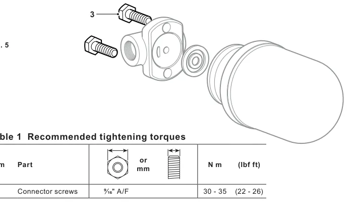
Specify the required differential-pressure rating and order a suitable pipeline connector or STS17.2 station separately. The UFT32 is a sealed, non-maintainable trap unit. No internal spares are available; service items are the connector screws and the complete trap unit supplied with gaskets and connector screws.
Safe operation depends on correct installation, commissioning, use and maintenance by qualified personnel in accordance with the operating instructions. Before work begins, assess access, lighting, pipeline contents, surrounding hazards and the effect of isolation on the complete system. Isolate pressure, vent safely to atmosphere and allow temperature to normalise. Do not assume a system is depressurised only because a gauge reads zero.
Confirm product suitability from the nameplate, technical information and operating limits. Check materials, pressure, temperature, installation position and flow direction. Protect non-self-draining equipment from freezing, use appropriate protective equipment and genuine replacement parts, and follow local permit-to-work and disposal requirements.
Verify that the selected UFT32 rating and connector are suitable for the service conditions.
Remove protective covers and ensure connector gasket faces are clean and undamaged.
Install the pipeline connector in its permitted orientation and flow direction according to its own instructions.
Fit the UFT32 with the supplied inner and outer gaskets and connector screws. Tighten connector screws evenly to the documented torque.
Provide safe isolation and depressurisation arrangements. Open isolation valves gradually to avoid system shock.
After installation or maintenance, verify that the system operates correctly and that safety devices remain effective. During operation, the float mechanism discharges condensate as it forms while the thermostatic air vent assists air removal, particularly during start-up.
The UFT32 is a sealed unit and is not intended for internal repair. Before removal, isolate the trap, vent pressure, allow it to cool and account for residual condensate. Replace the complete trap unit and its gaskets when service is required. Inspect connector faces and use the correct replacement screws and gaskets; recommission gradually and check for leakage.
Item | Supply form |
|---|---|
Connector screws | Set of two |
Complete UFT32 trap unit | Trap, inner and outer gaskets, and connector screws |
Always identify the model and pressure rating when ordering a replacement unit or service items.
Cast steel float and thermostatic steam trap for continuous condensate removal, with internal air removal and size-specific pressure-temperature limits.
The Spirax Sarco FTGS14 ball float steam trap uses stainless steel construction for continuous drainage duties where corrosion resistance and compact installation are important.
The Spirax Sarco FT43 ball float steam trap is suited to flanged connections, larger sizes and higher condensate loads in heat exchanger and process drainage duties.
The Spirax Sarco FT14 ball float steam trap is a model-specific product path inside the ball float steam trap range for users who already know FT14 and need a faster path into connection format, pressure class and replacement boundaries.


