
FT46-BALL-FLOAT-STEAM-TRAP
FT46 Stainless Steel Ball Float Steam Trap
FT46 is an austenitic stainless-steel ball float steam trap with automatic air venting, integral flanged connections and DN15–DN50 options for documented differential pressures up to 32 bar.
FT46 stainless steel ball float steam trap
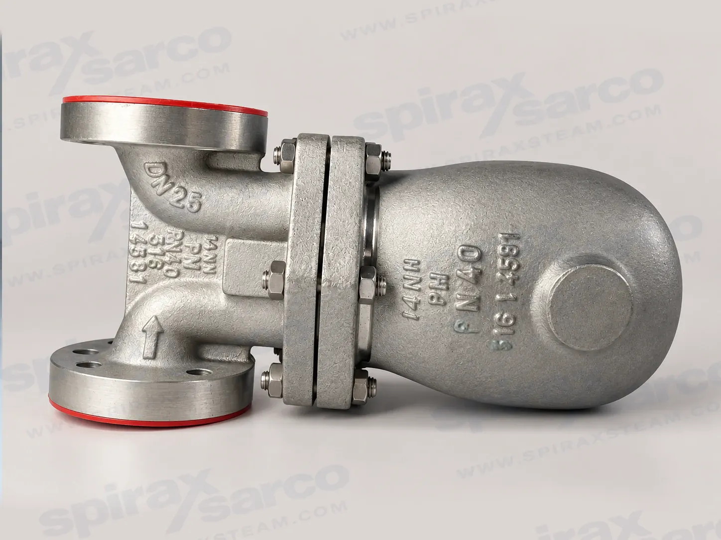
Spirax Sarco FT46 is an austenitic stainless steel ball float steam trap for continuous condensate drainage in steam systems. It combines an integrally flanged body, stainless steel working internals and a built-in automatic air vent in one maintainable assembly. The documented size range is DN15, DN20, DN25, DN40 and DN50, with differential-pressure designations from 4.5 bar to 32 bar. This makes the FT46 a practical choice where condensate must be removed as it forms, air must be cleared during start-up and the trap must tolerate a demanding stainless-steel process environment.
The product is intended for engineers selecting a complete drainage point rather than a nominal-size fitting in isolation. The correct choice depends on the condensate load, inlet pressure, backpressure, available differential pressure, connection standard, temperature, flow direction and the orientation of the drain point. The pressure designation and size must be selected together: for example, the documented FT46-14 option is limited to DN15, DN20 and DN25, while the 4.5 bar, 10 bar, 21 bar and 32 bar designations are shown for the relevant size groups. The technical information below keeps those conditions visible instead of treating the model name as a single universal rating. For a replacement duty that needs a different connection route, compare the published FT14 ball float steam trap page for its documented threaded or flanged options and pressure-class path. Where stainless construction and the installation boundary are the deciding factors, the published FTGS14 stainless steel ball float steam trap page provides a separate model-specific comparison route; neither model is an FT46 variant.
Continuous drainage with automatic air removal
A ball float trap responds to the density difference between hot condensate and steam. At start-up, the thermostatic air vent opens so air can bypass the main valve and leave the system. This reduces air binding while the system is warming. When hot condensate reaches the trap chamber, the air vent closes and the float rises. The float movement is transferred through the lever mechanism to the main valve, allowing condensate to discharge continuously as it forms. When steam reaches the chamber, the float falls and the main valve closes. The result is a drainage cycle that follows the load instead of waiting for a batch of condensate to accumulate.
This operating pattern is useful on heat-transfer equipment, process plant and steam distribution points where standing condensate can reduce heat transfer, disturb temperature control or contribute to waterhammer. It also helps the trap respond to changing loads without requiring an electrical signal. The air-vent arrangement is not a minor accessory: it affects start-up behaviour and temperature capability, so it must be confirmed against the chosen pressure variant. The current installation guide identifies a BP99/32 capsule for the 4.5–21 bar variants and a bimetallic air vent as standard for the 32 bar variant. The bimetallic element can also be requested on other variants, subject to the documented restrictions.
Stainless construction for flanged steam service
The FT46 body and cover are documented as austenitic stainless steel, with stainless steel float, lever, air-vent, support and related working parts. The exact technical data sheet also records the component material grades and the distinction between the DN15–DN25 mechanism and the DN40/DN50 mechanism with its inlet protection arrangement. This construction provides a robust basis for applications that require stainless wetted and internal surfaces, while the material still has to be checked against the actual condensate chemistry, cleaning regime and plant environment.
Connections are integrally flanged. The standard route is EN 1092 PN40 with face-to-face dimensions to EN 26554 Series 1. ASME B16.5 Class 150 and Class 300 flanges are available as documented options, with tapped UNC holes for the flange bolts. The body marking identifies the flow direction. When facing the body, DN15 to DN25 flow from left to right; DN40 and DN50 flow from right to left. This size-dependent direction is important when a replacement is planned for an existing line: the flange pattern alone does not confirm that the installed pipework is suitable.
The trap can be maintained without disturbing the pipework when the installation provides safe isolation and the required cover access. That feature reduces the amount of line breaking during planned maintenance, but it does not remove the need to isolate pressure, vent trapped fluid and allow the metal to cool. The installation and maintenance section below gives the working precautions, component procedures and torque values that govern the intervention.
Choose the pressure and air-vent arrangement
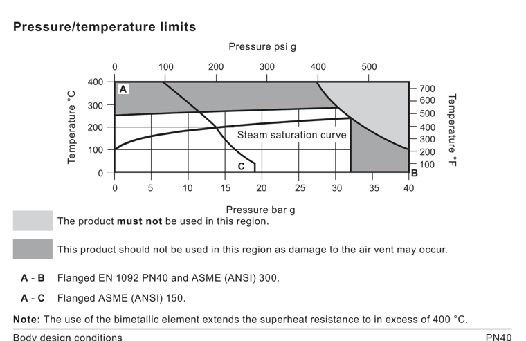
The current FT46 data in the installation guide defines a PN40 body design condition, a maximum allowable pressure of 40 bar g at 100 °C and a maximum allowable temperature of 400 °C at 27.4 bar g. For saturated steam, the maximum operating pressure is 32 bar g at 239 °C. The minimum allowable temperature is -10 °C and the minimum operating temperature is 0 °C; lower-temperature duties require confirmation. These values describe conditional boundaries, not independent targets. The pressure-temperature chart, connection class, air-vent type and actual operating point must be checked as one selection.
For the pressure designations, the maximum differential pressures are FT46-4.5 at 4.5 bar, FT46-10 at 10 bar, FT46-14 at 14 bar for DN15–DN25 only, FT46-21 at 21 bar and FT46-32 at 32 bar. DN40 and DN50 are limited to the options shown in the technical table. The product is documented as safe under full vacuum conditions. The maximum cold hydraulic test pressure is 60 bar g, but a complete trap with its internal mechanism fitted must not be subjected to more than 48 bar g. A cold test limit must never be repurposed as an operating rating.
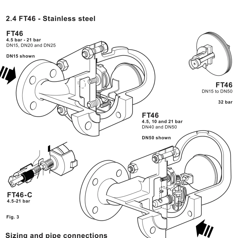
For superheated steam, the BP99/32 capsule is documented for 150 °C superheat at 0 bar g, reducing to 50 °C at 32 bar g. The bimetallic air vent extends superheat resistance to more than 400 °C in the conditions shown by the guide and has a separate 400 °C at 27.4 bar g operating limit. The manually adjustable needle-valve version, designated FT46-C, adds a steam-lock-release feature to the standard air vent. The steam-lock-release arrangement and bimetallic air vent cannot be used together, so the desired air-removal and steam-lock strategy must be specified before ordering.
Where the FT46 adds engineering value
The main benefit of the Spirax Sarco FT46 is the combination of continuous drainage, automatic start-up air removal, stainless construction and flanged serviceability. Continuous discharge is valuable when a heat exchanger, jacket, coil or process vessel needs condensate removed immediately to preserve heat-transfer area. Automatic air venting helps the plant warm through without leaving a pocket of non-condensable gas in the steam space. Integral flanges give a defined face-to-face installation and make the valve straightforward to isolate and service in a correctly arranged line.
The model is also suited to an installation programme where component access matters. The cover withdrawal distance for maintenance is a maximum of 200 mm in the installation guide. The trap should be fitted as close as possible to the drain point, with a short drop leg—typically 150 mm—immediately before the trap. An upstream strainer is recommended to protect the mechanism from line debris. Where condensate discharges into a return system with backpressure, a downstream check valve prevents the steam space from flooding when inlet pressure falls or steam is shut off.
These benefits depend on correct layout. A trap installed too far from the plant can steam-lock, allowing steam to occupy the connecting pipe and preventing condensate from reaching the float chamber. The FT46-C option can provide a controlled bypass for steam-lock release in suitable low-speed cylinder and similar duties. High-speed cylinder applications may need a separate external bypass because the adjustable needle valve cannot handle the larger blow-through requirement described in the installation guide. That distinction belongs in the application review, not in a default assumption that every FT46 needs the C option.
Application boundaries and selection checks
The installation guide describes the product for steam, air or water/condensate in the applicable Group 2 boundary. Before selection, check the fluid, material compatibility, maximum and minimum pressure, maximum and minimum temperature, differential pressure at the trap and any return-line backpressure. Consider whether the system can create waterhammer, whether the discharge is safe, whether the exposed valve needs protection from freezing and whether the valve is in a position where maintenance personnel can work safely. If the duty is still at the family-selection stage, compare the documented ball float steam trap family before fixing the FT46 connection and pressure designation.
FT46 should be installed in the direction marked on the body, with the float arm in a horizontal plane so that it rises and falls vertically. The body orientation and nameplate should read correctly when the installation is complete. The standard FT46 arrangement described here is horizontal with size-dependent flow direction; no vertical variant is being added to this single-model page without a verified product-specific source. The full installation block retains the source safety and orientation requirements.
When comparing materials or pressure classes, use the published FT43 selection page only as a clearly separate comparison route; it is not part of FT46 and its cast-iron construction must not be substituted for the stainless specification. For a wider choice of drainage principles, review the steam-trap range and the related steam trap selection guidance. These links support selection decisions while leaving FT46 as the sole product identity of this page.
Dimensions, maintenance and ordering
The exact FT46 data sheet records approximate weights from 10.8 kg for DN15 and DN20, 15.0 kg for DN25, 33.0 kg for DN40 and 43.0 kg for DN50. The dimension table in the technical block should be used for layout and lifting planning, with the usual allowance for gasket, bolt and surrounding pipework clearances. The body, cover, air vent and main valve assemblies are service parts in the documented maintenance system. DN15–DN25 use the main-valve assembly with float, while DN40 and DN50 use the separate main-valve assembly and float/lever arrangement with the specified inlet baffle components.
Before an enquiry is released, state the FT46 pressure designation, nominal size, flange standard, air-vent arrangement, any FT46-C steam-lock-release requirement, and any balance-line or drain-cock tapping requested at the time of order. State the installation direction and allow for the required maintenance withdrawal space. The price reference currently contains spare-part rows mentioning this family but no exact FT46 complete-unit row, so this page intentionally exposes no inferred price-table specification selector. The Spirax Sarco FT46 should be quoted only after the actual whole-unit configuration is confirmed.
FT46 selection summary
- Austenitic stainless-steel ball float steam trap with stainless working internals and built-in automatic air venting.
- DN15, DN20, DN25, DN40 and DN50 integrally flanged sizes with EN 1092 PN40 standard connections and ASME Class 150/300 options.
- Continuous condensate discharge, start-up air removal and online maintenance access when the line is safely isolated.
- FT46-4.5, -10, -14, -21 and -32 differential-pressure designations, selected with the size and operating conditions.
- BP99/32 capsule, bimetallic air-vent and FT46-C steam-lock-release arrangements subject to their documented compatibility limits.
- Confirm flow direction, pressure-temperature boundary, condensate load, return-line backpressure, strainer, check valve and maintenance access before ordering.
Scope of this technical information
This technical section keeps the verified FT46 information from the exact FT46 data sheet and the current FT46 pages of the installation guide. It covers DN15 to DN50, the documented pressure designations and FT46-C option. Data for adjacent models in the shared source documents is intentionally excluded.
Product description and connections
FT46 is an austenitic stainless-steel ball float steam trap with stainless-steel working internals and an automatic built-in air vent. It has integrally flanged connections and can be maintained without disturbing the pipework when correctly isolated. The body marking identifies the flow direction.
| Item | FT46 requirement or option |
|---|---|
| Sizes | DN15, DN20, DN25, DN40 and DN50 |
| Flow when facing the body | DN15–DN25: left to right; DN40 and DN50: right to left |
| Standard flange | EN 1092 PN40, face-to-face to EN 26554 Series 1 |
| Optional flanges | ASME B16.5 Class 150 (ANSI 150) and Class 300 (ANSI 300), face-to-face to EN 26554 Series 1 |
| ASME flange detail | Tapped UNC holes for flange bolts |
| Optional cover tapping | Top balance-line or bottom drain-cock connection, 3/8 inch BSP T Rp (ISO 7-1) or NPT, requested at order |
Pressure and temperature limits
| Condition | Value or qualification |
|---|---|
| Body design condition | PN40 |
| PMA, maximum allowable pressure | 40 bar g at 100 °C |
| TMA, maximum allowable temperature | 400 °C at 27.4 bar g |
| Minimum allowable temperature | -10 °C |
| PMO, saturated-steam maximum operating pressure | 32 bar g at 239 °C |
| TMO with capsule | 285 °C at 30 bar g |
| TMO with bimetallic air vent | 400 °C at 27.4 bar g |
| Minimum operating temperature | 0 °C; consult Spirax Sarco for lower temperatures |
| Vacuum | Safe for use under full vacuum conditions |
| Maximum cold hydraulic test pressure | 60 bar g |
| Test restriction with internals fitted | Do not subject the complete trap to more than 48 bar g |
The 2025 English installation guide is the controlling source for these current pressure and temperature boundaries. The older exact FT46 data sheet contains different historical limits; those values are not combined with the current limits above.
Maximum differential pressure
| Designation | DN15, DN20 and DN25 | DN40 and DN50 |
|---|---|---|
| FT46-4.5 | 4.5 bar | 4.5 bar |
| FT46-10 | 10 bar | 10 bar |
| FT46-14 | 14 bar | Not available in the cited table |
| FT46-21 | 21 bar | 21 bar |
| FT46-32 | 32 bar | 32 bar |
Air vent and optional arrangements
- The BP99/32 capsule is used on 4.5–21 bar variants and is documented for 150 °C superheat at 0 bar g, reducing to 50 °C at 32 bar g.
- The bimetallic air vent is fitted as standard to the 32 bar variant and is available on other variants on request. It increases the documented superheat resistance.
- FT46-C is the manually adjustable needle-valve arrangement that provides steam-lock release in addition to the standard air vent.
- The steam-lock-release arrangement and bimetallic air vent cannot be used together. Alternative arrangements require manufacturer confirmation.
Materials
| No. | Component | Material or grade as documented |
|---|---|---|
| 1 | Body | Austenitic stainless steel 316; 1.4408 / CF8M |
| 2 | Cover bolts and nuts | Austenitic stainless steel; A2.70 bolts and A4 nuts listed |
| 3 | Cover gasket | Austenitic stainless steel, BS 1449 304 S16 listed |
| 4 | Cover | Austenitic stainless steel 316 |
| 5 | Seat / main valve assembly | Stainless steel; DN15–DN25 seat BS 970 431 S29; DN40/DN50 assembly BS 3146 Pt2 ANC2 / BS 970 416 S37 |
| 6 | Seat / main-valve gaskets | Stainless steel, BS 1449 304 S11, for DN15–DN25; reinforced exfoliated graphite for DN40/DN50 main-valve gasket |
| 7 | Assembly screws, bolts and nuts | Stainless steel; BS 4183 18/8 screws, BS 970 304 S15 bolts and BS 6105 A4.80 nuts are listed by size |
| 8 | Float and lever mechanism | Stainless steel, BS 1449 304 S16 listed |
| 9 | Air-vent assembly | Stainless steel |
| 10 | Steam-lock-release device | Stainless steel, BS 970 303 S31 listed |
| 11–12 | Steam-lock-release gasket and seal | Stainless steel gasket and graphite seal |
| 13–15 | Support, pivot support and pivot pin | Stainless steel |
| 16 | Internal baffle, DN40/DN50 only | Stainless steel, BS 1449 304 S16 listed |
| 17 | Air-vent seat gasket | Stainless steel, BS 1449 409 S19 listed |
| 18 | Erosion baffle | Stainless steel, BS 970 431 S29 listed |
Dimensions and weights
The following values are approximate and use the dimension letters shown on the exact FT46 data sheet. Allow for the flange gasket, bolts, surrounding pipework and safe maintenance access during layout.
| Size | A (mm) | B (mm) | C (mm) | D (mm) | E (mm) | F (mm) | Mass (kg) |
|---|---|---|---|---|---|---|---|
| DN15 | 150 | 80 | 80 | 215 | 120 | 155 | 10.8 |
| DN20 | 150 | 80 | 80 | 225 | 120 | 165 | 10.8 |
| DN25 | 160 | 115 | 85 | 276 | 170 | 215 | 15.0 |
| DN40 | 230 | 130 | 115 | 326 | 200 | 200 | 33.0 |
| DN50 | 230 | 141 | 123 | 332 | 200 | 225 | 43.0 |
Flange face-to-face dimensions follow EN 26554 Series 1. The data sheet labels the dimensions and weights as approximate; confirm the supplied configuration before final support and lifting design.
FT46 start-up cold-water allowance
The following minimum added cold-water discharge values are from the FT46 rows of TI-S02-36. They represent the additional discharge available during start-up while the thermostatic air vent is open; they are not a replacement for a trap capacity selection.
| Pressure differential (bar) | 0.5 | 1 | 2 | 3 | 4.5 | 7 | 10 | 14 | 21 | 32 |
|---|---|---|---|---|---|---|---|---|---|---|
| Maximum to 21 bar | 450 | 600 | 780 | 1,040 | 1,140 | 1,350 | 1,530 | 1,750 | 2,300 | — |
| 32 bar only | 170 | 250 | 380 | 520 | 600 | 780 | 860 | 1,140 | 1,170 | 1,200 |
| Pressure differential (bar) | 0.5 | 1 | 2 | 3 | 4.5 | 7 | 10 | 14 | 21 | 32 |
|---|---|---|---|---|---|---|---|---|---|---|
| Maximum to 21 bar | 460 | 680 | 900 | 1,080 | 1,300 | 1,600 | 1,980 | 2,050 | 2,600 | — |
| 32 bar only | 90 | 120 | 350 | 460 | 600 | 850 | 900 | 1,020 | 1,200 | 1,300 |
Selection and ordering checks
State the FT46 size, pressure designation, flange standard and flow direction when ordering. Specify the air-vent arrangement, FT46-C requirement and any balance-line or drain-cock tapping at the time of order. Certification requirements, including EN 10204 3.1 where available, must also be stated at order placement. The pressure-temperature chart, actual condensate load and return-line conditions remain the final engineering checks.
Installation and Maintenance Guide
This FT46 section preserves the target-model safety, installation, operation and DN15-DN50 maintenance instructions from IM-S02-30 CMGT Issue 16. Read the complete supplied guide with the nameplate and current technical information before work starts. Safe operation depends on correct installation, commissioning, use and maintenance by competent personnel.
1. Safety information
1.1 Intended use and limits
- Check the FT46 nameplate and technical information against the intended service before installation. Confirm the fluid, material suitability, pressure, temperature and maximum/minimum values.
- The documented service boundary covers steam, air or water/condensate in Group 2. If the trap limit is lower than the system limit, provide a suitable protective device against dangerous overpressure or overtemperature.
- Determine the correct installation situation and flow direction. The FT46 flow direction is size dependent and is marked on the body; do not infer it from a similar trap.
- Do not expose the trap to external stresses from misaligned or unsupported pipework. The installer is responsible for considering and minimising those stresses.
- Remove connection protection and nameplate film before installation on steam or other high-temperature service.
1.2 Access, lighting and pipeline contents
Provide safe access, a guarded working platform where needed, adequate lighting and suitable lifting equipment before work begins. Establish what is in the pipeline, and what may have been in it previously, including flammable substances, hazardous materials and temperature extremes. Consider explosion risk, oxygen deficiency, dangerous gases, hot surfaces, fire, noise and moving machinery around the work area.
1.3 Pressure, temperature and isolation
Assess the effect of closing isolation valves or disabling controls on the complete system. Do not isolate a vent, alarm or protective device without a safe alternative. Isolate pressure and vent it safely to atmospheric pressure; never assume the system is depressurised only because a gauge reads zero. Allow temperature to normalise after isolation to avoid burns. Use double isolation and bleed arrangements where the plant risk assessment requires them.
1.4 Tools, clothing, permits and handling
- Have suitable tools and consumables ready and use genuine replacement parts.
- Assess protection needed against chemicals, hot or cold surfaces, noise, falling objects and eye or face hazards.
- Work must be carried out or supervised by a suitably competent person. Follow the site permit-to-work system and use warning notices where necessary.
- Assess the risk of manual handling for the 33.0 kg DN40 and 43.0 kg DN50 assemblies. Use suitable lifting equipment and a safe method rather than bodily force.
1.5 Residual hazards, freezing and disposal
The external surface may be very hot and can exceed 300 °C at maximum permitted conditions. The trap may not self-drain, so take care when dismantling or removing it. Protect an exposed trap from frost damage where condensate can remain inside. The product is recyclable when handled correctly; follow local disposal rules and check the current compliance information for substances of concern. If a product is returned after contamination or mechanical damage, provide written information about the hazards and precautions.
2. General product information
FT46 has integrally flanged connections, stainless-steel working internals and automatic air venting. The trap is continuous acting: it removes condensate as soon as it forms. The documented FT46 sizes are DN15, DN20, DN25, DN40 and DN50. DN15–DN25 flow left to right when facing the body; DN40 and DN50 flow right to left. The body and cover markings, nameplate and flow arrow must be read together.
The BP99/32 capsule is used on the 4.5–21 bar variants and is suitable for the documented superheat conditions. The bimetallic element is standard on the 32 bar variant and can be requested for other variants. FT46-C adds a manually adjustable needle valve for steam-lock release. The steam-lock-release arrangement and bimetallic air vent cannot be used together.
3. Installation
Before installation: observe the safety information, verify the technical limits and confirm that the selected nuts, bolts and gaskets meet the applicable industry standard.
- Install the trap in the direction of flow shown by the arrow on the body. Keep the float arm in a horizontal plane so it rises and falls vertically.
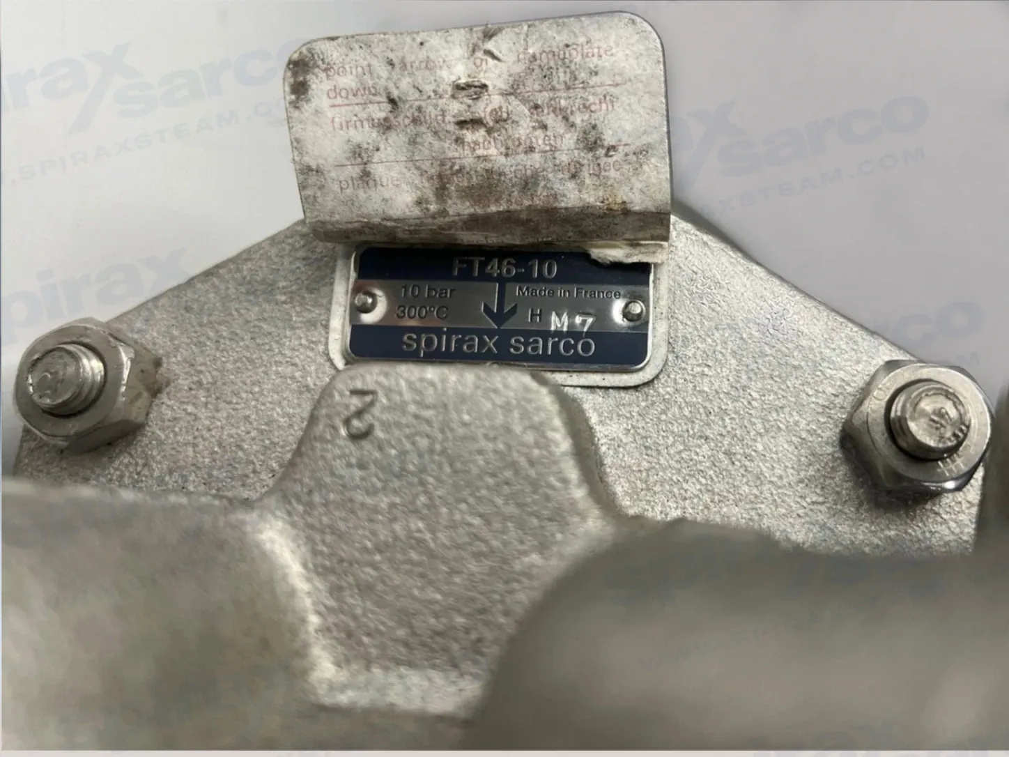
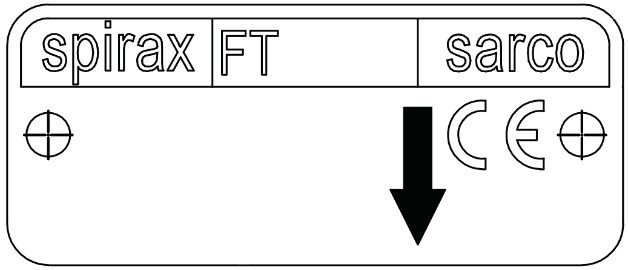
- Use the nameplate and body writing to check the installed orientation. The writing should be the correct way up when the trap is correctly oriented.
- Fit an upstream strainer where practicable and maintain steam quality using sound engineering practice.
- Fit the trap below the steam-system outlet with a short drop leg immediately before it, typically 150 mm (6 in). Without a drop leg, steam can pass over condensate at low load and reach the trap.
- Position the trap as close as possible to the outlet of the plant being drained. Excessive distance can cause steam-lock and waterlogging.
- Where a return line has backpressure, fit a non-return/check valve downstream of the trap. This prevents the steam space from flooding when inlet pressure falls or steam is shut off.
- If the trap is exposed, lag it or drain it with a separate small thermostatic trap suitable for the location. Do not allow freezing condensate to damage the body.
- Leave enough space to remove the cover for maintenance. The maximum cover withdrawal distance is 200 mm (8 in).
For rotating cylinders and siphon or dip-tube applications, assess steam-lock risk. The FT46-C adjustable needle valve can provide a controlled steam-lock-release bypass in suitable low-speed cylinder service. The factory setting is one-half turn, giving an approximate 22 kg/h steam bypass at 10 bar; turn anticlockwise to increase bypass and clockwise to reduce it. High-speed cylinder service may require an external bypass because the adjustable needle valve cannot handle the larger blow-through flow.
If the trap discharges to atmosphere, route the discharge to a safe location because the fluid may be hot. Provide suitable protection and consider the effect of discharge noise, spray and temperature on people and nearby equipment.
4. Commissioning
After installation or maintenance, confirm that the system is fully functioning. Test alarms and protective devices. Check for leaks, confirm the flow direction and verify that condensate reaches the trap. Raise pressure in a controlled way and watch for waterhammer, abnormal noise or leakage. Do not use a cold hydraulic test value as an operating pressure.
5. Operation
The float trap is continuous acting. On start-up, the thermostatic air vent allows air to bypass the main valve and prevents air binding. Hot condensate closes the air vent tightly; when condensate enters the main chamber the float rises and opens the main valve. The valve closes when steam reaches the chamber and the float falls. This cycle removes condensate at the moment it forms.
The installation must be kept within the selected FT46 pressure-temperature and differential-pressure limits. If the trap is not draining correctly, investigate flow direction, air vent condition, condensate load, inlet pressure, return-line backpressure, strainer condition and possible steam-lock before changing the pressure designation.
6. Maintenance and spare parts
6.1 Preparation and general servicing
Before a maintenance programme, read the safety information, isolate all pressure sources, vent the trap safely, allow it to cool and confirm that no hazardous fluid remains. With suitable isolation, repairs can be carried out with the trap in the pipeline. Use genuine replacement parts. On reassembly, clean all joint faces and make sure the dowel locates correctly in the cover.
6.2 Main valve assembly for DN15, DN20 and DN25
- Unscrew the support frame, pivot frame and valve seat.
- Ensure that the seat and gasket faces are clean and dry; do not use gasket paste.
- Fit the new gasket and valve seat to the body.
- Attach the support and pivot frames with the assembly set screws without fully tightening.
- Fit the float arm to the pivot frame using the pin and centre the valve head on the seat orifice.
- Tighten the assembly set screws to the torque in Table 1.
6.3 Main valve assembly for DN40 and DN50
- Unscrew the four bolts or nuts and remove the main valve assembly and gasket.
- Clean and dry the gasket faces.
- Fit the new gasket and main valve assembly, including the inlet baffle plate.
- Tighten the bolts or nuts evenly to the torque in Table 1.
6.4 Air-vent assemblies
For the capsule air vent, remove the spring clip, capsule and spacer plate, then unscrew the seat and remove the frame and gasket. Clean the faces, fit the new gasket, frame and seat, and tighten to the recommended torque before assembling the new spacer plate, capsule and clip. For the bimetallic air vent, remove the element assembly and gasket, clean the faces, fit the new gasket and element and tighten evenly to the recommended torque.
Table 1 — Recommended tightening torques
| Item | Size or tool | Fastener | Torque (N m) |
|---|---|---|---|
| Cover | DN15/DN20/DN25 · 17 A/F | M10 x 30 | 29–33 |
| Cover | DN40 · 24 A/F | M12 x 60 | 60–66 |
| Cover | DN50 · 24 A/F | M16 x 70 | 80–88 |
| Capsule air vent | DN15–DN25 · 17 A/F | — | 50–55 |
| Assembly screws | DN15–DN25 | M5 x 20 | 2.5–2.8 |
| Assembly bolts | DN40 · 10 A/F | M6 x 20 | 10–12 |
| Assembly bolts | DN50 · 13 A/F | M8 x 20 | 20–24 |
| Air-vent/SLR item | 17 A/F | — | 50–55 |
| SLR item | 22 A/F | — | 40–45 |
6.5 Available spare assemblies
| Spare description | Component numbers | Ordering detail |
|---|---|---|
| Main valve assembly with float, DN15/DN20/DN25 | 5, 6, 7, 8, 9, 10, 11 | State size and horizontal installation arrangement |
| Main valve assembly with erosion deflector, DN40/DN50 | 5, 6, 7, 12, 26 | State size and horizontal installation arrangement |
| Ball float and lever, DN40/DN50 | 8 | State size |
| Air-vent assembly | 17, 18 | State capsule or bimetallic type |
| Steam-lock-release and capsule air-vent assembly | 17, 18, 19, 20, 21 | State FT46 pressure range and size |
| Complete gasket set, packet of three sets | 3, 6, 18, 20 | State size and pressure range |
Always order by the description in the available-spares table and state the size, FT46 model/pressure range, connection arrangement and whether a capsule or bimetallic air vent is required. The maintenance example is a capsule air-vent assembly for a DN20 FT46-4.5 horizontal trap.
7. DN40 and DN50 inlet-baffle arrangement
The DN40 and DN50 horizontal mechanisms use an inlet baffle plate over the inlet port. This prevents inlet flow from affecting the float operation. When fitting the DN40 mechanism, assemble the supplied baffle plate under the mechanism retaining bolts. When fitting the DN50 mechanism, replace the two uppermost studs with the longer supplied studs, place the spacer collars and baffle plate over those studs, then replace the nuts and tighten normally. The correct baffle position shown in the source guide must be followed during reassembly.