
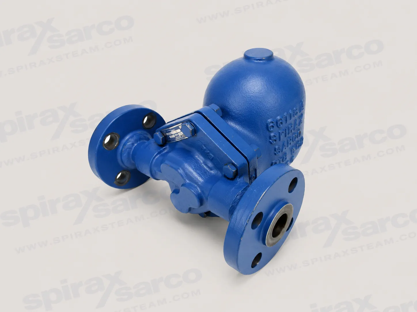
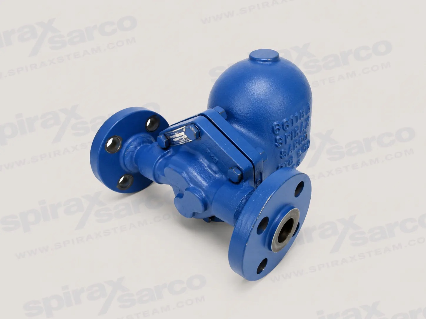
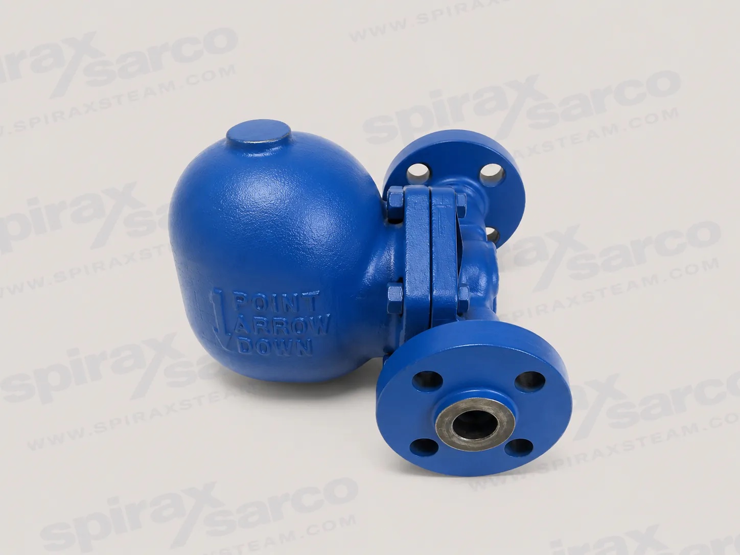
FT450 float and thermostatic steam trap
The Spirax Sarco FT450 is a cast steel float and thermostatic steam trap for continuous condensate removal from steam equipment. Its mechanical float modulates a double-seated main valve so condensate leaves at approximately steam temperature as it forms, while a separate thermostatic air vent discharges air and other non-condensable gases during start-up and operation. This makes the FT450 a practical choice for process duties where the drainage point, differential pressure and service access can be defined clearly before ordering.
The model is documented across two size envelopes. The smaller range covers 3/4 in to 2 in connections and uses model-specific pressure limits from FT450-4.5 through FT450-32. The high-capacity range covers 3 in (DN80) and 4 in (DN100). These ranges share the same float and thermostatic operating principle, but their connection arrangements, pressure-temperature limits, dimensions and capacity information must be selected from the correct technical section.
Continuous condensate removal at steam temperature
A float trap responds directly to the level of condensate in its body. As condensate enters, the float rises and positions the main valve to discharge the incoming load continuously. The discharge behaviour is therefore suited to equipment that needs condensate removed as it is produced rather than held for an intermittent cycle. The independent thermostatic air vent helps clear start-up air and non-condensable gases that would otherwise reduce heat-transfer performance and delay warm-up.
The FT450 can operate against back pressure provided the outlet pressure remains below the inlet pressure. For a Spirax Sarco FT450 capacity review, the usable capacity is governed by differential pressure, defined as inlet pressure minus outlet pressure, as well as by the selected orifice and connection. A pressure number without its size, model pressure class and outlet condition is not enough to select a trap. The capacity tables and curves below should be read with the actual steam pressure, return pressure, condensate load and warm-up requirement.
Applications and engineering value
For the 3/4 in to 2 in range, the documented applications include process equipment, equipment controlled by modulating temperature-control valves, unit heaters, air-heating coils, heat exchangers and steam main drip stations. The continuous discharge characteristic is useful where condensate backing up into a heat-transfer surface would affect temperature control or where a drip point must drain reliably while the steam main remains in service.
The 3 in and 4 in versions are intended for higher condensate loads from reboilers, large heat exchangers, other large process equipment and large absorption chillers. The large-trap technical sheet also identifies use in combination with a 4 in pressure powered pump. Where the wider system requires condensate transport beyond the trap, the related condensate pump options should be considered alongside the available differential pressure and return-system back pressure. That application reference identifies a possible system arrangement, not a universal selection rule.
Selection should start with the wider steam trap range and then narrow to a float and thermostatic configuration that matches the duty. For a Spirax Sarco FT450 order review, the high-capacity steel body and relatively large service footprint make space, lifting and maintenance access part of the selection rather than afterthoughts.
Construction for demanding steam service
The FT450 body is cast steel or carbon steel, with stainless steel internal parts. The large-range technical information identifies the body as ASTM A216 WCB and the float as ASTM A240 Type 304. The internal arrangement includes the float, linkage, main valve mechanism and thermostatic air vent. For the small range, an optional bimetal air vent is identified for the FT450-4.5, -10, -14, -21 and -32 configurations when superheated-steam service requires it. The broader steam air vent and air eliminator range provides related system context, but the FT450 air-vent choice must still be part of the order review rather than assumed from the base model name.
The body is designed for horizontal in-line installation. The documented design also allows service without disturbing the connected piping, which can reduce the scope of a maintenance intervention when isolation, lifting access and replacement parts have been planned correctly. Serviceability does not mean the trap can be opened under pressure: both supply and return sides must be isolated, trapped pressure relieved and the body allowed to cool before disassembly.
Pressure and temperature boundaries
FT450 range | Documented selection boundary | What must be checked |
|---|---|---|
3/4 in to 2 in | PMO varies by model trim from 65 psi g (4.5 bar g) to 465 psi g (32 bar g). | Model trim, air-vent range, flange rating, operating temperature and differential pressure. |
3 in (DN80) and 4 in (DN100) | PMO 450 psi g (31 bar g); 650 °F (343 °C) at 450 psi g and up to 750 °F (400 °C) at pressures up to 375 psi g (26 bar g). | Connection type, pressure shell limits, return pressure, support load and service clearance. |
These values are conditional operating limits, not a blanket rating for every FT450 arrangement. The small-range document gives a separate pressure/temperature graph and limits for NPT, socket weld and ANSI 300/600 construction, with ANSI 150 units limited by the flange rating. The large-range document gives its own pressure/temperature curve and allowable limits. The correct document section must be used for the selected size and connection.
Connections, capacity and physical space
Small FT450 sizes are described with NPT, socket weld connections to ANSI B16.11 and ANSI 150, 300 or 600 raised-face flanges. The 3 in high-capacity version is available with NPT, socket weld or flanged connections, while the 4 in version is flanged in the large-range data sheet. Connection selection affects the pressure envelope, face-to-face dimensions and installation method. It should be confirmed together with the line standard, drain arrangement and available downstream pressure.
Capacity is not selected from nominal pipe size alone. Use the hot-condensate capacity table or curve for the FT450 configuration, then check that the connection piping can carry the resulting flow. The large-range capacity graph explicitly marks a region where trap capacity may exceed the flow capacity of the connection piping. A sound enquiry therefore includes the condensate load, steam pressure, return pressure, required safety margin, start-up load and whether the load is hot or cold condensate.
Physical dimensions matter particularly for the 3 in and 4 in trap. The large unit weighs approximately 485 lb (220 kg), has mounting legs and requires overhead access for cover withdrawal. The installation guide also gives a 32 in (813 mm) withdrawal distance and notes the cover weight. For a smaller unit, the technical sheet gives size-specific dimensions and separate NPT/SW and flanged weights. The technical information below should be used to reserve the final envelope.
Installation and maintenance planning
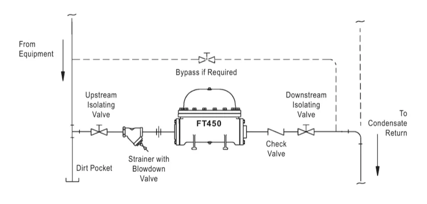
The trap should be installed firmly and horizontally, with the inlet at or preferably below the equipment drain point. The body flow markings must be followed. The inlet line should be blown down before installation, and a strainer should be installed upstream to protect the mechanism from pipe debris. Full-flow isolation valves should permit service, and a downstream check valve is recommended in the large-trap installation arrangement to help prevent backflow.
Reserve access above the cover and provide a stable support for the mounting feet. Outdoor installations need protection against freezing because condensate may not drain completely from the body when operation stops. Bypass piping is not recommended because of the possibility of misuse; if a bypass is required by the plant design, its valve must shut off tightly and the bypass should be at least one line size smaller than the trap line.
For upstream protection, review the available pipeline strainer and filter range alongside the trap arrangement. The strainer is a system accessory and is not an FT450 option. It should be sized and installed for the actual steam and condensate duty, with blowdown access that allows the inlet line and strainer to be cleaned without exposing personnel to pressure.
Routine service includes inspection and cleaning of the valve mechanism, valve heads and seats, float, air vent and gasket seating surfaces. The large-trap guide specifies that the bimetal air vent is factory calibrated and not repairable; suspected failure calls for replacement of the complete assembly. Worn valve mechanism parts are likewise addressed through complete assembly replacement where specified. These instructions are provided in the installation and maintenance section below and should be followed with the current document available to the service team.
What to confirm before ordering
Confirm that the product is the Spirax Sarco FT450 float and thermostatic trap and identify whether the duty falls in the 3/4 in to 2 in or 3 in to 4 in document range.
Provide inlet steam pressure, outlet or return pressure, condensate load, start-up load and the required operating temperature. Calculate differential pressure from the actual inlet and outlet conditions.
Choose the nominal size and connection type, then verify the applicable ANSI flange rating or socket-weld/NPT standard, pressure envelope and face-to-face dimensions.
For the small range, confirm the FT450 pressure trim and whether the documented optional bimetal air vent is required for superheated service.
For the large range, confirm support steelwork, lifting method, 32 in cover withdrawal clearance, certification/inspection requirements and any pressure powered pump arrangement.
Confirm upstream strainer, isolation, downstream check valve, drain/blowdown access and safe maintenance isolation before release for manufacture or supply.
FT450 selection summary
A Spirax Sarco FT450 selection is strongest when the model trim, size envelope, connection, differential pressure and service temperature are treated as one engineering decision. The product offers continuous mechanical condensate discharge, integral air removal and service access without disturbing the pipe connections, but the published limits remain conditional on the exact range and installation. Use the technical tables and installation instructions below to turn the duty data into an auditable configuration.
Product scope
The FT450 is a cast steel float and thermostatic steam trap. The float modulates the main valve to discharge condensate continuously at approximately steam temperature. A separate thermostatic air vent discharges non-condensable gases.
Range | Sizes | Connections | Construction |
|---|---|---|---|
Small range | 3/4 in, 1 in, 1-1/2 in, 2 in | NPT; SW to ANSI B16.11; ANSI 150, 300 or 600 RF flanged | Cast steel body; stainless steel internals |
High-capacity range | 3 in (DN80), 4 in (DN100) | 3 in: NPT, SW or flanged; 4 in: flanged | Carbon steel body; stainless steel internals |
The following pressure and temperature values are range-specific. Do not apply the small-range PMO table to the 3 in or 4 in trap, or the large-range rating to a small-range trim.
Pressure and temperature limits
3/4 in to 2 in FT450
Model trim | PMO maximum operating pressure |
|---|---|
FT450-4.5 | 65 psi g (4.5 bar g) |
FT450-10 | 145 psi g (10 bar g) |
FT450-14 | 200 psi g (14 bar g) |
FT450-21 | 300 psi g (21 bar g) |
FT450-32 | 465 psi g (32 bar g) |
With the optional bimetal air vent, the technical sheet gives a maximum operating temperature of 750 °F (400 °C) at operating pressures below 505 psi g (35 bar g). The pressure/temperature graph defines the permissible thermostatic-air-vent region. The product is stated to be safe for full vacuum conditions.
For NPT, SW, ANSI 300 and ANSI 600 construction, the pressure shell design conditions are 535 psi g at 650 °F (37 bar g at 343 °C) and 505 psi g at 750 °F (35 bar g at 400 °C). The TMA condition is 750 °F at 0-505 psi g (400 °C at 0-35 bar g). ANSI 150 flanged units are limited by the flange rating.
3 in and 4 in FT450
Limit | Documented condition |
|---|---|
PMO | 450 psi g (31 bar g) |
Maximum operating temperature | 650 °F at 450 psi g (343 °C at 31 bar g) |
Higher temperature condition | 750 °F at up to 375 psi g (400 °C at 26 bar g) |
PMA | 425 psi g at 700 °F (29 bar g at 371 °C); 375 psi g at 750 °F (26 bar g at 400 °C) |
TMA | 750 °F at 375 psi g (400 °C at 26 bar g) |
The installation guide also records the standard-configuration cold hydraulic test pressures: 585 psi g (40.3 bar g) for SW and NPT and ANSI 300 units, and 285 psi g (19.6 bar g) for ANSI 150 units.
Construction and internal arrangement
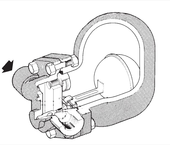
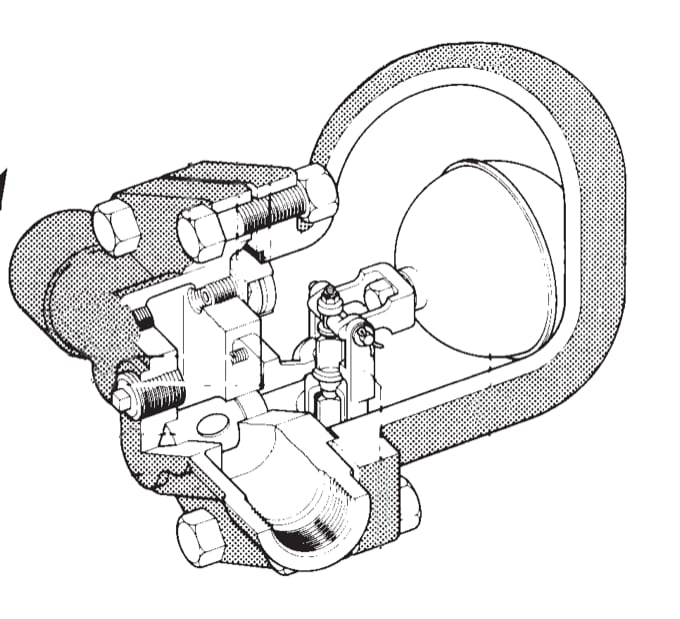
The technical information identifies a cast steel or carbon steel body with stainless steel internals. For the 3 in and 4 in range, the body is ASTM A216 WCB and the float is stainless steel ASTM A240 Type 304. The large-range parts list also identifies graphite with stainless steel insert for the cover gasket, alloy-steel ASTM A193 Grade B7 cover bolts, steel lockwashers, ASTM A194 Grade 2H cover nuts in the small-range construction, a graphite mechanical gasket, stainless-steel main valve assembly and screws, forged-steel companion flange and stainless-steel air-vent parts.
The internal mechanism is intended to be serviceable without disturbing the inlet and outlet piping. The small-range sample specification describes a balanced-pressure thermostatic air vent capable of withstanding 45 °F (25 °C) of superheat and resisting waterhammer without damage. The optional bimetal air vent is intended for the stated superheat operating region and must be selected against the actual pressure-temperature duty.
Capacity and differential pressure
Capacity is a function of differential pressure: inlet pressure minus outlet pressure. The table below gives the FT450 hot-condensate capacities for the small range at 1/4, 1/2, 1, 2 and 5 psi differential pressure. Values are in lb/hr. An asterisk identifies each orifice of a double-seated mechanism.
Model | Size | Orifice in (mm) | 1/4 psi | 1/2 psi | 1 psi | 2 psi | 5 psi |
|---|---|---|---|---|---|---|---|
FT450-4.5 | 3/4 in | 0.157 (4) | 110 | 155 | 219 | 310 | 440 |
FT450-10 | 3/4 in | 0.126 (3.2) | 65 | 91 | 129 | 183 | 275 |
FT450-14 | 3/4 in | 0.106 (2.7) | 47 | 66 | 93 | 132 | 203 |
FT450-21 | 3/4 in | 0.079 (2.0) | 25 | 35 | 50 | 70 | 110 |
FT450-32 | 3/4 in | 0.063 (1.6) | 16 | 22 | 31 | 44 | 66 |
FT450-4.5 | 1 in | 0.276 (7) | 389 | 550 | 778 | 1,100 | 1,655 |
FT450-10 | 1 in | 0.205 (5.2) | 202 | 285 | 403 | 570 | 870 |
FT450-14 | 1 in | 0.185 (4.7) | 150 | 212 | 300 | 425 | 640 |
FT450-21 | 1 in | 0.157 (4) | 110 | 155 | 219 | 310 | 440 |
FT450-32 | 1 in | 0.126 (3.2) | 65 | 91 | 129 | 183 | 275 |
FT450-4.5 | 1-1/2 in | 0.689* (17.5*) | 1,209 | 1,710 | 2,418 | 3,420 | 5,733 |
FT450-10 | 1-1/2 in | 0.591* (15*) | 624 | 882 | 1,247 | 1,764 | 2,734 |
FT450-14/21/32 | 1-1/2 in | 0.531* (13.5*) | 407 | 575 | 813 | 1,150 | 1,764 |
FT450-4.5 | 2 in | 1.122* (28.5*) | 4,289 | 6,065 | 8,577 | 12,130 | 18,522 |
FT450-10 | 2 in | 0.807* (20.5*) | 1,559 | 2,205 | 3,118 | 4,410 | 6,950 |
FT450-14/21/32 | 2 in | 0.657* (16.7*) | 780 | 1,103 | 1,559 | 2,705 | 3,528 |
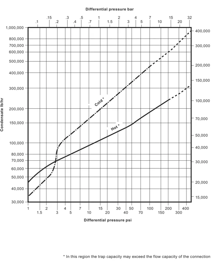
The source capacity graph also expresses the orifice data in millimetres, including 1.6 mm, 2 mm, 2.7 mm, 3.2 mm, 4.7 mm, 5.2 mm, 13.5 mm, 15 mm, 16.7 mm, 17.5 mm and 20.5 mm. Its metric capacity axis includes a labelled 400 kg/h mark. Select capacity from the actual differential pressure and condensate condition. Do not use nominal size or a single pressure value as a substitute for the capacity curve and the connection-piping check.
Dimensions and weights
3/4 in to 2 in approximate dimensions
Size (DN) | A | A1 | B | C | D | E | F | G | H | NPT/SW weight | Flanged weight |
|---|---|---|---|---|---|---|---|---|---|---|---|
3/4 in (20) | 6.1 (155) | 10.0 (254) | 2.6 (66) | 2.6 (66) | 6.4 (163) | 4.7 (119) | 7.4 (188) | 4.0 (102) | - | 18.0 lb (8.2 kg) | 23.8 lb (10.8 kg) |
1 in (25) | 6.5 (165) | 10.4 (264) | 4.5 (114) | 3.3 (84) | 8.2 (208) | 6.3 (160) | 9.2 (234) | 5.8 (147) | - | 28.0 lb (12.7 kg) | 33.0 lb (15.0 kg) |
1-1/2 in (40) | 9.8 (249) | 14.0 (356) | 5.1 (130) | 3.1 (79) | 9.7 (246) | 7.7 (196) | 11.0 (279) | 6.4 (163) | 4.7 (119) | 55.1 lb (25.0 kg) | 64.0 lb (29.0 kg) |
2 in (50) | 11.8 (300) | 16.0* (406*) | 5.5 (140) | 3.6 (91) | 9.9 (251) | 7.7 (196) | 11.5 (292) | 6.5 (165) | 6.0 (152) | 68.0 lb (31.0 kg) | 82.0 lb (37.2 kg) |
The asterisk on the 2 in A1 dimension identifies the ANSI 600 value of 16.5 in (419 mm). The large-range pressure/temperature graph includes a steam saturation curve with the 32 to 212 °F scale shown in the source drawing.
3 in and 4 in approximate dimensions
Dimension | Value | Scope or note |
|---|---|---|
Overall length | 27.75 in (705 mm) | 3 in NPT or SW |
Overall length | 39.0 in (990 mm) | 3 in or 4 in ANSI 150/300 RF flanged |
Mounting hole diameter | 0.625 in (15.9 mm) | Mounting legs |
Withdrawal distance | 32.0 in (813 mm) | Above the mounting feet for cover service |
Approximate product weight | 485 lb (220 kg) | Installation guide separately states approximately 550 lb (250 kg) partially filled with condensate |
Certification and serviceability
The 3 in and 4 in technical information states that the product is available with certification to EN 10204 3.1 and designed in accordance with ASME VIII Division 1. Certification and inspection requirements must be stated at order placement.
The trap can be maintained without disturbing piping connections. Complete isolation from both supply and return pressure is required before service. The detailed isolation, installation, maintenance and troubleshooting requirements are provided in the following installation and maintenance guide section.
Installation and Maintenance Guide
Description and operation
Installation
Maintenance and repair
Troubleshooting
1. Description and operation
The Spirax Sarco 3 in (DN80) and 4 in (DN100) FT450 is a high-capacity float and thermostatic steam trap.
The float adjusts the position of the double-seated main valve so that condensate is discharged continuously at the same rate as it enters the trap. Air present at start-up, or air that collects in the trap during operation, is discharged through the integral bimetal air vent into a standpipe connected to the main valve mechanism housing downstream of the main valve.
The FT450 may be used on superheated steam systems within the pressure-shell design conditions. It will operate against any back pressure lower than the inlet pressure. Differential pressure is the inlet pressure minus outlet pressure and determines the trap capacity.
Principal features shown in the source cross-section include the inlet companion flange, inlet baffle, removable cover, air vent, outlet casting and mounting holes. The bolted outlet casting is not a flange and must not be removed.
2. Installation
Before installing the trap, carefully blow down the inlet piping to remove existing pipe debris.
Caution: Before installation, inspection or maintenance, the trap must be completely isolated from both supply and return line pressure.
The trap must be supported firmly in a horizontal position. The four feet are drilled with 5/8 in diameter (15.9 mm) holes to accept 1/2 in (12.7 mm) mounting bolts. The total weight of the trap partially filled with condensate is approximately 550 lb (250 kg). Observe the "in" and "out" markings on the body.
Position the trap with the inlet no higher than, and preferably below, the equipment drain point. If possible, provide a drop leg and dirt pocket ahead of the trap. Keep the horizontal distance between the equipment drain point and the trap no longer than necessary.
Install a pipeline strainer ahead of the trap and locate full-flow isolating valves so the trap can be serviced. A check valve after the trap is recommended to prevent backflow.
Provide access above the trap for servicing. The cover weighs approximately 150 lb (68 kg), and its withdrawal distance is 32 in (813 mm) from the bottom of the mounting feet.
Bypass piping is not recommended because of the possibility of misuse. If a bypass is installed, it should be at least one size smaller than the trap line size, and the bypass valve must be capable of tight shut-off.
NPT and SW traps are shipped with a companion flange bolted to the inlet. This flange can be welded or threaded to the inlet piping. The trap is supplied with a flanged, NPT or SW outlet connection as required. The bolted outlet casting is not a flange and must not be removed.
Because condensate cannot drain completely from the body, a trap installed outdoors can freeze if it is not in continuous operation. If an interruption in steam supply is possible, provide for draining or tracing the trap body.
When placing the trap in service, no priming is necessary. Open the inlet isolating valve slowly to prevent damage to the trap and piping system. The equipment, piping and trap should be warmed slowly to operating conditions.
3. Maintenance and repair
This trap can be serviced without disturbing the piping connections.
Caution: Isolate the trap from both supply and return line pressure before any servicing or disassembly. Pressure that may remain in the trap after the isolating valves are closed must be relieved before opening the trap. Open the blowdown valve on the strainer ahead of the trap and wait until the trap has cooled.
Remove and save the cover bolts and lockwashers. Lift the cover from the body, taking care not to damage the air-vent standpipe, which extends approximately 7-1/2 in (190 mm) above the body-cover flange surface.
Remove the bottom plug to drain condensate remaining in the body.
Using a suitable solvent, remove dirt and incrustation from the mechanism, body and cover. Inspect the body and cover for condensate corrosion.
Remove the main valve mechanism assembly and gasket. Inspect the valve linkage and pins for wear or damage and ensure that the pins are secured by their retaining washers.
Inspect the valve heads and seats for damage, wear or wiredrawing. If mechanism parts are worn or damaged, the guide recommends replacement of the complete assembly.
Inspect the float for damage and replace it if necessary. A collapsed float is evidence of extremely severe and dangerous waterhammer conditions that must be corrected before the trap is returned to service.
Remove all traces of the old mechanism gasket. Clean and inspect gasket seating surfaces. Install the new or cleaned mechanism assembly with a new gasket and a small amount of jointing paste. Tighten the mechanism cap screws to 50-55 ft lbf (68-75 Nm).
The bimetal air vent assembly is factory calibrated and is not repairable. If malfunction is suspected, replace the complete assembly. Tighten the new air vent and gasket into the adapter coupling to 27-31 ft lbf (37-42 Nm).
Remove old gasket traces from the body and cover, and make sure the seating surfaces are clean and undamaged. Fit a new gasket with a thin coating of jointing paste. Install and tighten the cover bolts with lockwashers to 250-275 ft lbf (339-373 Nm).
Service the strainer ahead of the trap as required so that its screen remains unobstructed. Return the trap to service by opening the isolating valves slowly; open the downstream valve first.
4. Troubleshooting
Very low load
Like any double-seated valve, the FT450 main valve may leak very slightly when closed. If the condensate load falls below the residual leakage rate, approximately 0.4% of full load, the valve may pass a very small amount of live steam in extremely unusual circumstances.
Flash steam at discharge
Because condensate is discharged close to steam temperature, part of it can re-evaporate, or flash. The discharge can therefore be a high-velocity mixture of liquid condensate and flash steam. This should not be mistaken for live steam loss.