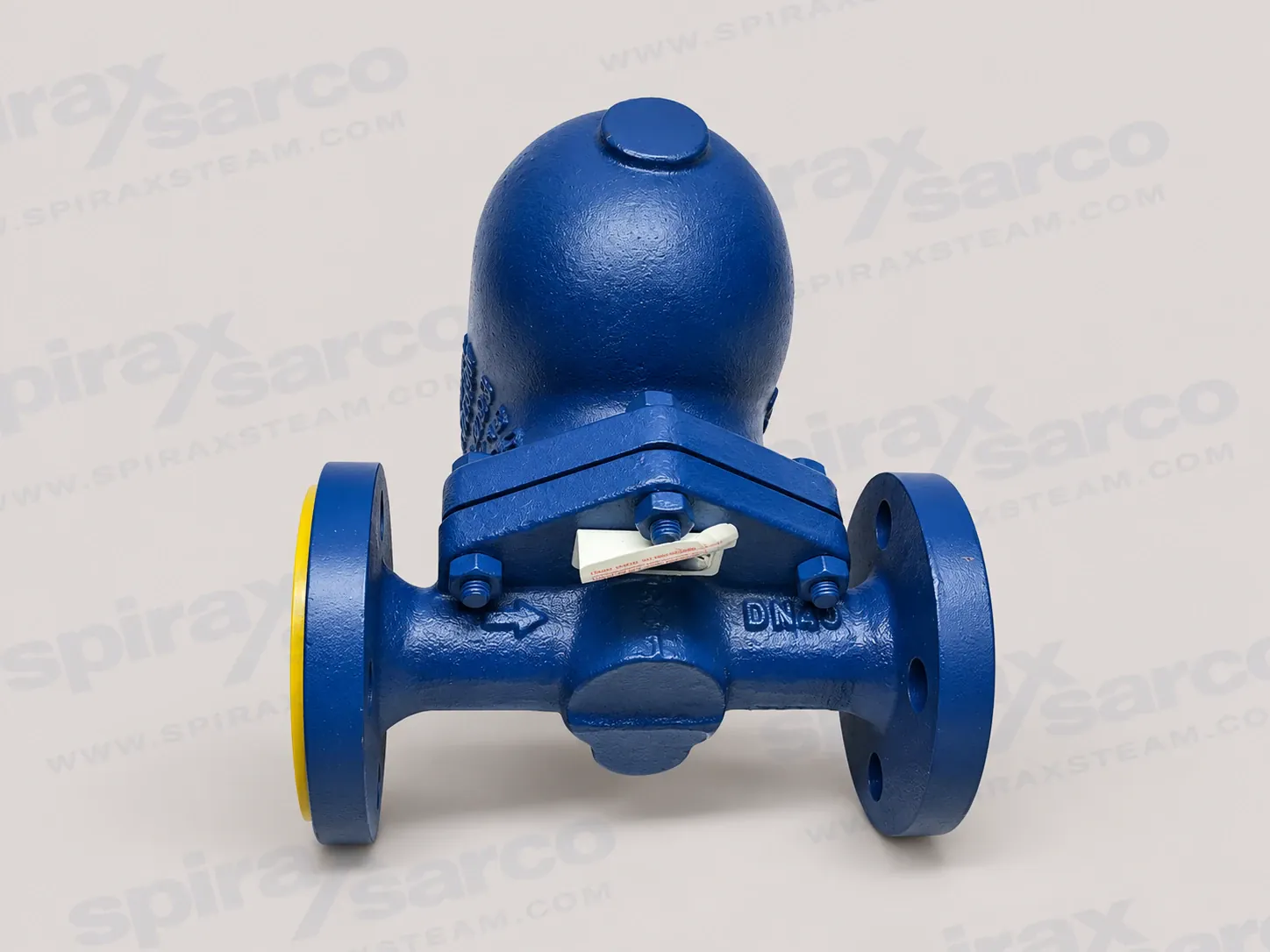
Spirax Sarco FT44 carbon steel ball float steam trap
Spirax Sarco FT44 is a flanged carbon steel ball float steam trap for removing condensate from steam systems while retaining steam under the documented operating conditions. It combines a carbon steel body and cover with stainless steel working internals and an automatic air vent. The float-operated main valve is intended to discharge condensate continuously as the float responds to the liquid level, while the air vent helps clear air during start-up. This makes the FT44 a practical choice for steam drainage duties where reliable condensate removal, a flanged connection and in-line maintenance are important.
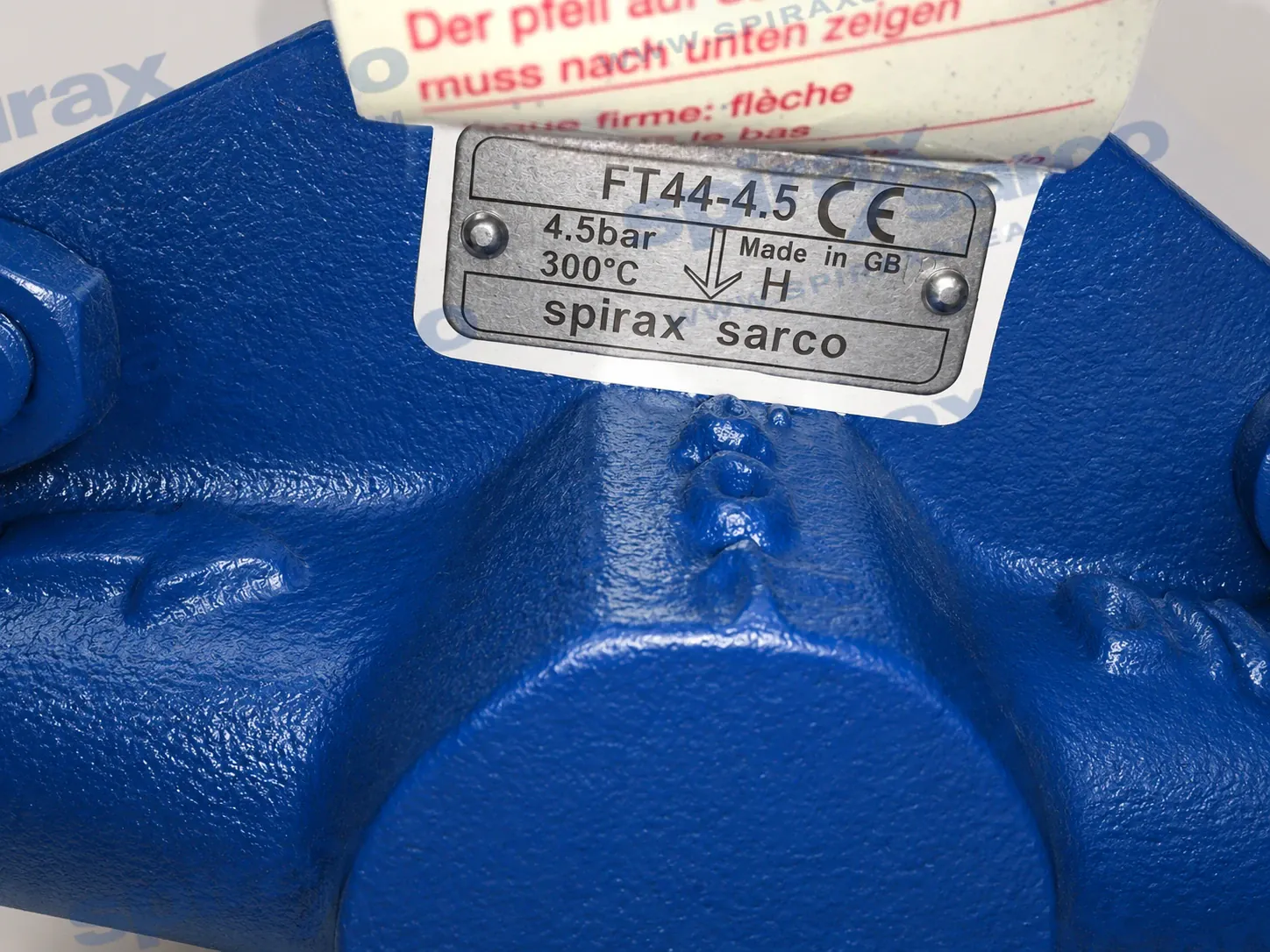
The FT44 page covers one product identity across the documented DN15 to DN50 and DN80 to DN100 size ranges. The size groups have different technical sheets and must be checked separately. The smaller range offers the FT44-4.5, FT44-10, FT44-14, FT44-21 and FT44-32 differential-pressure designations, with FT44-14 limited to the smaller sizes. The DN80 and DN100 range is documented with FT44-4.5, FT44-10, FT44-21 and FT44-32. The pressure designation is part of the selection, not an interchangeable suffix to add after the order is placed.
For a wider explanation of condensate removal, the steam trap selection guide provides the system-level context. This product introduction then focuses on the FT44 construction, operating envelope, installation arrangement and ordering checks needed for a single-model enquiry.
How the FT44 ball float trap works
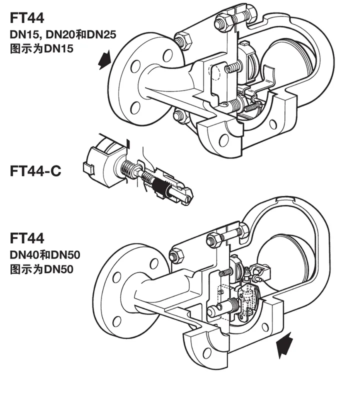
Condensate entering the trap raises the float and opens the main valve in response to the liquid level. As the condensate is discharged, the float falls and the valve closes against the available differential pressure. The ball-float action is suited to continuous drainage because the main valve responds to the presence of condensate rather than waiting for a fixed time interval. The built-in automatic air vent provides a separate path for air and other non-condensable gases during start-up, helping the steam space reach operating conditions without treating accumulated air as if it were condensate.
The FT44 uses a BP99/32 capsule for superheated-steam service. The documented superheat capability is 150 deg C at 0 bar g and 50 deg C at 32 bar g. Those values are operating conditions for the capsule and should be considered together with the trap pressure-temperature graph, not quoted as a universal superheat allowance at every pressure. The operating fluid, system pressure, temperature and the consequences of a failure still need to be reviewed before the trap is selected.
The automatic vent and the float mechanism serve different functions. The vent deals with air during start-up, while the float and main valve handle liquid condensate during operation. The resulting assembly is useful on steam mains drainage and process equipment where cold-start behaviour, air removal and continuous condensate discharge all matter. It is not a replacement for a safety valve, pressure-reducing valve or control valve, and the surrounding steam system still needs its own isolation, protection and drainage provisions.
Carbon steel body and serviceable internals
The FT44 body and cover are carbon steel, while the main valve, float linkage, air vent, supports and internal baffle arrangements use stainless steel components as specified for the size and connection arrangement. The combination gives the trap a robust flanged pressure boundary with corrosion-resistant working parts. The exact material table, including gasket and steam-lock-release components, is retained in the technical information below so that procurement and maintenance records can be checked against the supplied configuration.
The trap is designed to be maintained without disturbing the pipework when suitable isolation and access are provided. This is useful where a flanged trap is installed in a fixed steam main or process line and removing the whole body would create unnecessary downtime. Service still requires the line to be isolated, safely vented and cooled, and the work must be completed by competent personnel using the installation and maintenance instructions. In-line maintainability reduces disturbance to the pipework; it does not remove the need for pressure and temperature control.
A manual adjustable needle valve option is identified as FT44-C. It adds a steam-lock-release function to a horizontal FT44 arrangement and must be stated at the time of ordering. FT44V is the vertical installation option, with flow downwards only. These documented variants help match the trap to the layout, but they do not change the page identity or make the page an unrestricted catalogue for every FT family member.
When material selection is the deciding factor, a flanged cast-iron ball-float option can be reviewed through the FT43 ball float steam trap page. That link is a material-selection route, not a statement that FT43 is included in the FT44 specification. A stainless-steel body requirement can be routed to the FTGS14 ball float steam trap page for a separate product review.
Sizes, flange standards and flow direction
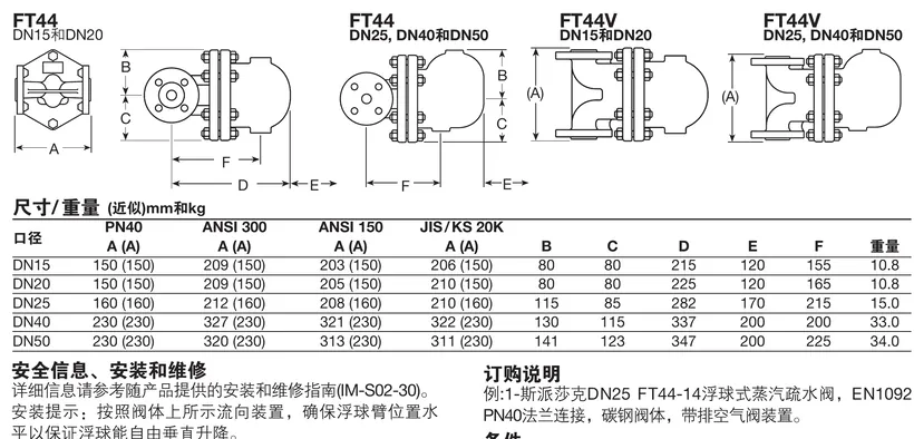
FT44 DN15, DN20, DN25, DN40 and DN50 are documented with integral flanged connections. EN 1092 PN40 is the standard flange arrangement, with face-to-face dimensions related to EN 26554 Series 1. ASME B16.5 Class 150 and Class 300 and JIS/KS 20 options are available as documented alternatives. When a non-standard flange is required, the flange class, face-to-face dimension and bolting detail should be recorded in the enquiry rather than assumed from the nominal size.
DN80 and DN100 are also flanged and are documented with EN 1092 PN40, EN 1759-1, ASME Class 150/300 and JIS/KS 20 arrangements. The DN80-DN100 technical sheet specifies horizontal installation only. The DN15-DN50 standard FT44 may be installed horizontally; FT44V is the vertical downflow option where the layout requires it. The body arrow must always be used to determine the actual direction of flow.
For smaller screwed ball-float requirements outside the FT44 flange scope, the FT14 ball float steam trap page provides a separate selection route. It should not be treated as an adapter or substitute for the FT44 flange pattern. Keeping the connection family separate avoids ordering a correct model with an incompatible piping arrangement.
Pressure and temperature boundaries
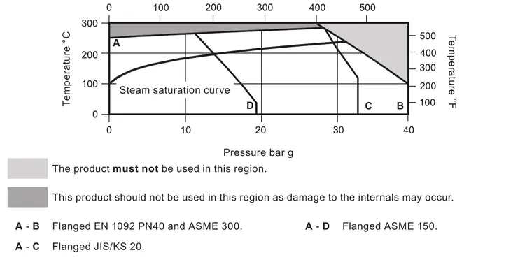
For DN15-DN50, the body design condition is PN40. The maximum allowable pressure is 40 bar g at 100 deg C. The maximum operating pressure for saturated steam is 32 bar g at 239 deg C, and the maximum operating temperature is 285 deg C at 28.5 bar g. The minimum allowable temperature is -10 deg C and the minimum operating temperature is 0 deg C; lower operating temperatures require consultation. DN40 and DN50 are limited to a maximum operating pressure equal to their selected maximum differential pressure.
The smaller size group is available with maximum differential pressures of 4.5, 10, 14, 21 and 32 bar. FT44-14 is documented for DN15, DN20 and DN25 and is not provided for DN40 or DN50. The complete operational trap must not be subjected to a pressure greater than 48 bar because the internal mechanism may be damaged. The designed cold hydraulic test pressure is 60 bar g, but a test pressure with internals fitted must remain within the applicable differential-pressure limit.
For DN80-DN100, the body design condition remains PN40 and the maximum allowable pressure is 40 bar g at 100 deg C. The maximum operating pressure is 32 bar g at 239 deg C, with a maximum operating temperature of 300 deg C at 27.5 bar g. The documented differential-pressure options are 4.5, 10, 21 and 32 bar. There is no FT44-14 entry for this size range. The low-temperature boundary and the 60 bar g cold hydraulic test condition must be checked from the DN80-DN100 sheet, not carried over from the smaller-range table without qualification.
The pressure-temperature graph defines prohibited regions and flange-specific limits. It is important when the system operates near the saturated-steam curve, when a Class 150 or JIS/KS connection is selected, or when the process uses superheated steam. Pressure, temperature, differential pressure and downstream backpressure interact; a single nameplate pressure is not enough to establish suitability.
Applications and system integration
The FT44 is suited to steam main drainage, process equipment drainage and other condensate duties that remain within the documented pressure-temperature and differential-pressure limits. Continuous float operation can be valuable where condensate load changes during start-up or normal production. The automatic air vent is also relevant to systems where air removal affects warm-up. The application review should include condensate load, start-up load, steam pressure, temperature, available differential pressure and the return-line pressure at the trap outlet.
At start-up, the air vent contributes additional cold-water discharge while the trap is warming. The FT44 start-up data show different minimum additional discharge values for DN15-DN25, DN40-DN50 and DN80-DN100, and distinguish traps rated up to 21 bar from those rated for 32 bar. A system with frequent cold starts, intermittent operation or a large initial condensate load should use those tables when checking the drain arrangement. The values describe the additional cold-water discharge from the air-vent function; they do not replace a full capacity calculation.
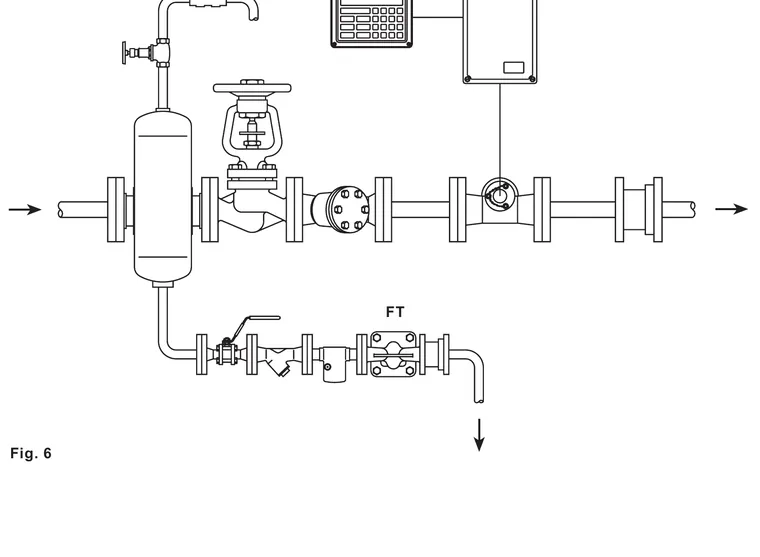
For a closed condensate return, consider a downstream non-return valve where reverse flow or backpressure could occur. Backpressure must remain within the product limit because excessive downstream pressure can prevent the main valve from opening or closing correctly. For an atmospheric discharge, terminate the outlet in a safe location and account for hot condensate, splash, noise and the potential need for a diffuser. A sight glass or trap-monitoring arrangement can be considered where the operating condition needs to be checked without disturbing the trap.
Installation, maintenance and ordering checks
Install the FT44 with the body arrow in the direction of flow and keep the float arm in a horizontal plane so that the float can move freely. A small drop leg before the trap is recommended where the pipe arrangement requires it, and the trap should be positioned close to the drainage point. Provide upstream and downstream isolation, adequate access for cover and mechanism removal, and support the connected pipework independently so external loads are not transferred into the trap.
Before maintenance, isolate the steam and condensate connections, vent pressure safely to atmosphere, allow the body to cool and confirm that the work area is safe. The guide identifies separate maintenance arrangements for DN15-DN50 and DN80-DN100. Main valve assemblies, air-vent assemblies, gaskets, float/lever components and the DN40-DN50 erosion-deflector arrangement must be ordered by the exact size, pressure designation and horizontal or vertical orientation. Recommended tightening torques are part of the service procedure and should be taken from the applicable table.
An enquiry for Spirax Sarco FT44 should state the nominal size, FT44 pressure designation, horizontal or FT44V vertical orientation, flange standard, operating pressure and temperature, condensate load, expected backpressure, start-up duty and any FT44-C or drilled-cover option. Certification or inspection requirements should also be stated at order placement. For a Spirax Sarco FT44 steam trap selection, keeping these operating details with the model reference allows the final configuration to be checked against the correct size-range document.
Spirax Sarco FT44 should therefore be selected as a complete operating case rather than as a model number alone. The technical information and installation sections that follow preserve the detailed dimensions, pressure limits, start-up discharge data, safety conditions, maintenance sequence and spare-parts boundaries needed to complete that review.