
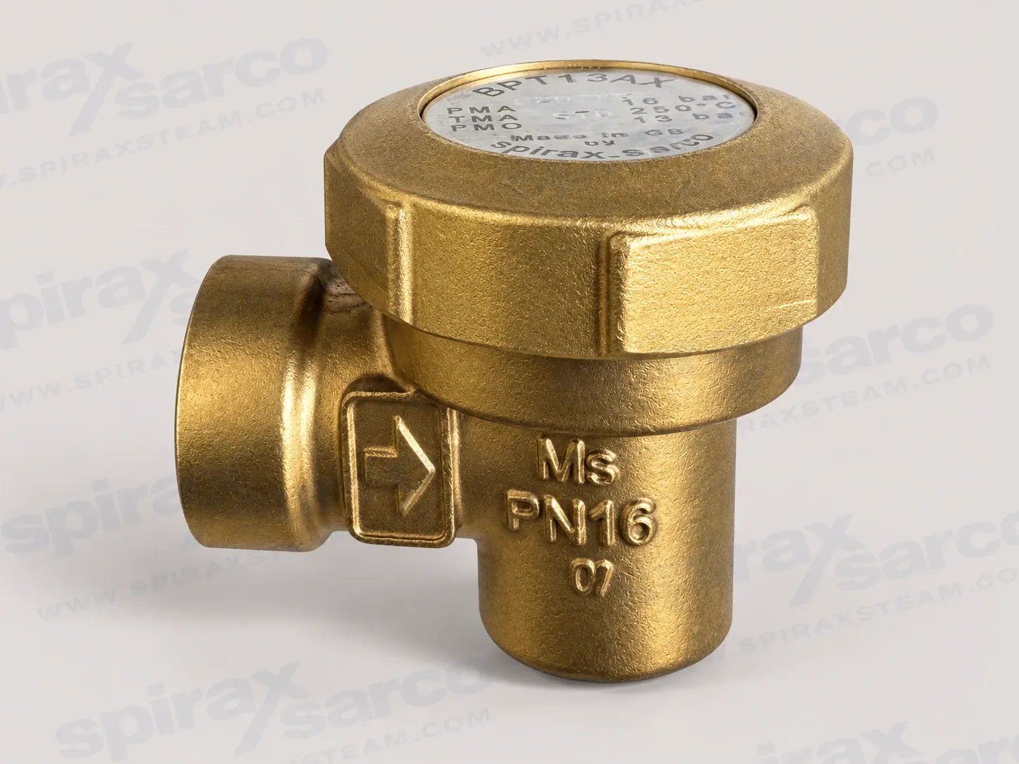
BPT13
BPT13 Balanced Pressure Thermostatic Steam Trap
BPT13 is a maintainable brass-bodied balanced pressure thermostatic steam trap with screwed BSP or NPT connections for documented steam, air or water/condensate service within its pressure, temperature and differential-pressure limits.
Spirax Sarco BPT13 balanced pressure thermostatic steam trap
Spirax Sarco BPT13 is a readily maintainable, brass-bodied balanced pressure thermostatic steam trap for removing condensate from steam systems. Its operating element is a liquid-filled capsule that responds to the temperature around the trap, so the valve opens during cold start-up and closes as condensate approaches steam temperature. This combination gives the BPT13 a practical way to discharge air and condensate while holding back live steam within the documented operating envelope.
The product is built for threaded small-bore connections and is documented for steam, air or water/condensate in Group 2 applications. The body and cap are brass, while the capsule and principal working parts are stainless steel. The assembly is designed to be serviced rather than discarded, which is useful when the trap is installed in a location where routine inspection, capsule replacement or seat maintenance is part of the plant maintenance plan.
How the balanced pressure capsule works
The BPT13 capsule contains a special liquid with a boiling point below that of water. At start-up, the surrounding conditions are cold and the capsule is relaxed. The valve is away from its seat, leaving a wide passage for air removal and early condensate discharge. As the condensate becomes hotter, heat transfers into the capsule liquid. The liquid boils before steam reaches the trap, increasing vapour pressure inside the capsule and expanding it against the valve seat. The trap then closes as the temperature approaches the selected operating relationship.
When the trap loses heat to the surrounding pipework or cooling leg, the capsule fill condenses and the capsule contracts. The valve opens again and releases condensate. The cycle repeats as the temperature changes. This is the characteristic balanced pressure action: the closing point follows the saturation relationship rather than being a fixed temperature unrelated to steam pressure. The result is useful in systems that need automatic air release during warm-up and condensate removal during normal operation.
Capsule fill selection
The capsule fill should be stated when ordering because it changes the discharge relationship. The standard STD fill operates at approximately 12 degrees C below steam saturation temperature. A SUB fill operates at approximately 24 degrees C below saturation and can be considered where sub-cooled condensate discharge is required. The NTS fill operates at approximately 4 degrees C below saturation and is intended for critical applications where condensate should be discharged closer to steam temperature. These are operating relationships, not a substitute for checking the actual pressure, temperature and heat-load conditions.
Before ordering, confirm the fill marking, connection thread, nominal size and flow direction against the nameplate and the current technical information. A capsule choice should follow the process requirement and the consequences of retaining condensate; it should not be selected only because it is the default option.
Connections and construction
BPT13 connections are available in 3/8 inch, 1/2 inch and 3/4 inch sizes with screwed BSP T Rp connections to ISO 7-1 or NPT connections. The small threaded format suits compact steam and condensate pipework where a serviceable trap is required without a flanged assembly. Confirm the thread standard on the order and make sure the mating pipe and fittings use the same standard. The documented technical sheet presents dimensions by connection arrangement, so the exact ordered arrangement must be confirmed before allocating maintenance clearance or replacing an existing trap.
The brass body and cap are specified as BS EN 12165 CW 617N. The stainless steel capsule, spring, spacer plate, valve seat and valve seat gasket form the working assembly, and the cap seal is a high-fluorine fluorocarbon O-ring on current models. This material description identifies the construction documented for BPT13; it does not remove the need to check chemical compatibility, pressure, temperature and local regulations for the complete installation.
Pressure and temperature boundaries
The body design condition is PN16. The maximum allowable pressure is 16 bar g at 120 degrees C, while the maximum allowable temperature is 250 degrees C at 7 bar g. The maximum operating pressure is 13 bar g at 220 degrees C, and the maximum operating temperature is 250 degrees C at 7 bar g. The minimum allowable temperature is -20 degrees C and the minimum operating temperature is 0 degrees C. The maximum cold hydraulic test pressure is 24 bar g.
These values are conditional points on the published pressure-temperature envelope, not independent ratings that can be combined without review. The trap must not be used in the prohibited regions of the envelope or beyond the operating range because the internals may be damaged. Check the actual steam pressure, condensate temperature, start-up condition and any pressure-reducing or return-line effects before choosing a trap. The technical information and installation guide remain the controlling documents for the full curve, warnings and site-specific assessment.
Installation that supports reliable operation
Install the capsule in a horizontal plane with the cap at the top. A drop or cooling leg immediately before the trap is preferred so that cooling condensate does not back up into the steam main. Confirm the direction of fluid flow and leave enough space to remove the cover. The installation guide specifies a minimum withdrawal distance of 55 mm for cover removal. Isolation valves on the supply and return sides allow the trap to be made safe for inspection, replacement and capsule or seat maintenance.
Open isolation valves slowly when returning the trap to service, then check for leaks and correct operation. If the outlet discharges to atmosphere, use a diffuser where recommended to cushion high-velocity discharge and reduce noise and erosion. The outlet must discharge to a safe location because the fluid may be about 100 degrees C. The BPT13 is not self-draining, so installations exposed to freezing conditions need protection against frost damage after the system is isolated.
Applications and selection checks
The BPT13 is most appropriate where a compact threaded balanced pressure trap is needed for steam and condensate service, where automatic air removal during start-up is valuable, and where the maintenance team needs access to the capsule and seat. It can also be considered for the documented air or water/condensate duties, but any change of medium requires a material, pressure and temperature suitability review. Other fluids must not be assumed suitable from the product name alone.
Confirm the medium, minimum and maximum operating pressure, temperature range and condensate load.
Select 3/8 inch, 1/2 inch or 3/4 inch size from the actual pipe and calculated load, then confirm BSP T Rp or NPT thread standard.
Choose STD, SUB or NTS capsule fill to match the required condensate discharge temperature and process sensitivity.
Check the pressure-temperature envelope rather than applying PN16, PMO or TMO as an unrestricted standalone rating.
Provide a horizontal capsule position, cap-up orientation, a suitable cooling leg, isolation valves and the 55 mm maintenance withdrawal space.
Plan the discharge route, diffuser and frost protection where the trap may discharge to atmosphere or remain cold while isolated.
State any certification or inspection requirement when ordering; a manufacturer's Typical Test Report is available when requested at order placement.
Maintenance and capacity planning
The maintainable construction makes the BPT13 suitable for a planned service routine. Before opening the trap, isolate both the supply and return sides, allow pressure to normalise safely, and wait for the metal to cool. A service check normally includes the capsule, valve seat, seat gasket, spacer plate, spring and cap seal, with joint faces cleaned before reassembly. The installation guide gives separate tightening torques for a current O-ring and an earlier cap gasket. The exact spare and capsule reference should be matched to the nameplate rather than selected from a similar-looking trap.
Capacity is governed by differential pressure and the condition of the condensate, not simply by the nominal thread size. The technical curve distinguishes hot-water and cold-water capacity, so the design review should identify the expected start-up load, running load, inlet pressure, return pressure and selected capsule fill. A higher differential pressure can change the available discharge rate, while a return system or cooling arrangement can change the pressure actually available across the trap. Use the published curve as a first selection check, then verify the complete condensate load and operating cycle with the system designer.
Position within the steam-trap range
For broader selection work, the wider steam-trap selection provides the surrounding product and application context. Where the project is comparing balanced pressure designs, review another balanced-pressure steam trap alongside the carbon-steel BPC32YCV balanced-pressure steam trap, the BPT13 operating limits, connection requirements and maintenance access. The correct choice depends on the actual service conditions and discharge objective, not on the model name alone.
Spirax Sarco BPT13 should therefore be specified with its size, thread standard, capsule fill, operating data and required certification. The technical information below supplies the full limits, materials and capacity curves, while the installation and maintenance information preserves the safety checks, installation sequence and service instructions needed to put the trap into operation responsibly.
Description
BPT13 is a readily maintainable brass-bodied balanced pressure thermostatic steam trap. The capsule fill, connection standard, size and operating conditions must be stated or checked when ordering.
Capsule fill and operation
The standard capsule is marked STD and operates at approximately 12 °C below steam saturation temperature. A SUB capsule operates at approximately 24 °C below saturation temperature. For critical applications, select an NTS fill capsule, which operates at approximately 4 °C below saturation temperature.
Standards and certification
BPT13 fully complies with the requirements of the European Pressure Equipment Directive 2014/68/EU. A manufacturer's Typical Test Report is available. State certification or inspection requirements when placing the order.
Sizes and pipe connections
3/8 inch, 1/2 inch and 3/4 inch screwed BSP T Rp (ISO 7-1) or NPT.
Pressure and temperature limits (ISO 6552)
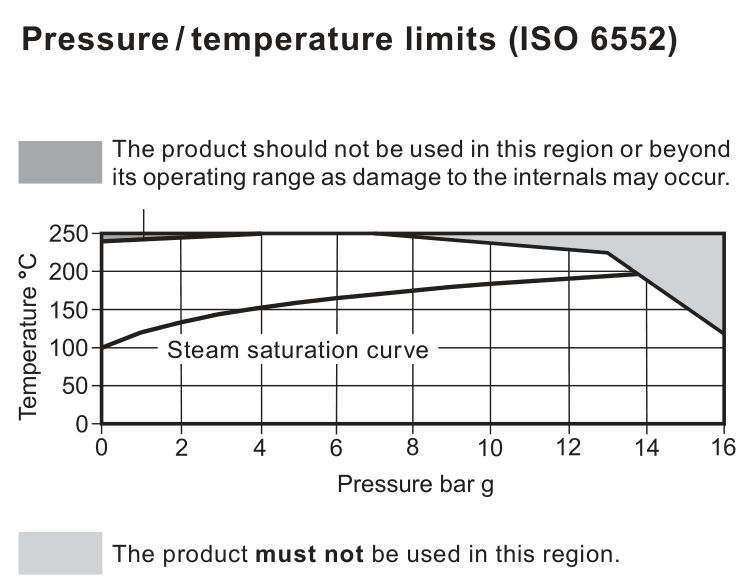
Condition | Limit |
|---|---|
Body design conditions | PN16 |
PMA, maximum allowable pressure | 16 bar g at 120 °C |
TMA, maximum allowable temperature | 250 °C at 7 bar g |
Minimum allowable temperature | -20 °C |
PMO, maximum operating pressure | 13 bar g at 220 °C |
TMO, maximum operating temperature | 250 °C at 7 bar g |
Minimum operating temperature | 0 °C |
Maximum cold hydraulic test pressure | 24 bar g |
Local regulations may restrict use below the quoted conditions. Do not use the test pressure as an operating pressure.
Materials
No. | Part | Material | Specification |
|---|---|---|---|
1 | Body | Brass | BS EN 12165 CW 617N |
2 | Cap | Brass | BS EN 12165 CW 617N |
3 | O-ring | Synthetic rubber, high-fluorine fluorocarbon | - |
4 | Capsule | Stainless steel | - |
5 | Spring | Stainless steel | BS 2056 302 S26 |
6 | Spacer plate | Stainless steel | BS 1449 304 S16 |
7 | Valve seat | Stainless steel | BS 970 431 S29 |
8 | Valve seat gasket | Stainless steel | BS 1449 304 S11 |
The source document also describes optional family components associated with particular connection arrangements. They are not treated as unqualified BPT13 inquiry specifications here.
Dimensions and weights
Dimensions and weights depend on the selected connection arrangement and size. Confirm the current technical information for the exact ordered configuration before setting pipe supports, replacement clearances or lifting arrangements.
Capacity guidance
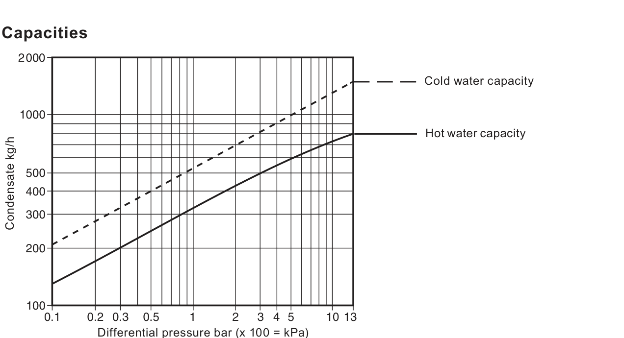
The data sheet presents separate cold-water and hot-water capacity curves. Differential pressure is shown in bar, with the chart axis noting the relationship to kPa. Use the curve as selection guidance and verify the actual condensate load, inlet pressure, back pressure and capsule fill before final sizing.
Installation note
Install the capsule in a horizontal plane with the cap at the top, preferably with a drop leg immediately preceding the trap. See the Installation and Maintenance Instructions IM-P122-02 for the full safety, installation and maintenance requirements.
Disposal
BPT13 is recyclable when due care is taken. If recycling involves a temperature approaching 315 °C, caution is required because the fluorocarbon rubber component may decompose.
Ordering information
State the product code, size, connection standard, capsule reference and any certification or inspection requirement. Confirm the exact connection arrangement from the order documentation and nameplate; do not infer it from the unqualified BPT13 code alone.
1. Safety information
Safe operation is guaranteed only when the product is installed, commissioned, used and maintained by qualified personnel in accordance with these instructions. General installation and safety instructions for pipeline and plant construction, together with the proper use of tools and safety equipment, also apply.
1.1 Intended use
Use the Installation and Maintenance Instructions, nameplate and Technical Information Sheet to check suitability for the intended application. BPT13 is designed for steam, air or water/condensate in Group 2 gases and Group 2 liquids under the documented Pressure Equipment Directive conditions. Other fluids may be possible, but suitability must be confirmed with Spirax Sarco.
Check material suitability, pressure, temperature and their maximum and minimum values. If the product limit is lower than the system limit, or if a malfunction could create dangerous overpressure or overtemperature, include a safety device to prevent the limit being exceeded. Determine the correct installation situation and direction of flow. The product is not intended to withstand external stresses from the connected system, so the installer must provide suitable precautions. Remove connection covers and protective film from nameplates where appropriate before high-temperature service.
1.2 Access and lighting
Provide safe access and, where necessary, a guarded working platform before working on the product. Arrange suitable lifting equipment when required. Provide adequate lighting, especially where detailed or intricate work is required.
1.3 Hazardous liquids, gases and environment
Consider the current and previous contents of the pipeline, including flammable materials, substances hazardous to health and temperature extremes. Assess explosion risk areas, lack of oxygen in tanks or pits, dangerous gases, hot surfaces, fire hazards during welding, excessive noise and moving machinery.
1.4 The system and pressure system
Consider the effect of the proposed work on the complete system. Isolation of vents or protective devices, electrical isolation, or the loss of controls and alarms may put other plant or personnel at risk. Operate isolation valves gradually to avoid system shocks.
Isolate pressure safely and vent to atmospheric pressure. Consider double isolation, double block and bleed, and locking or labelling closed valves. Do not assume the system is depressurised because a gauge reads zero.
1.5 Temperature
Allow time for temperature to normalise after isolation to avoid burns. If the O-ring has been exposed to a temperature approaching 315 °C (599 °F) or higher, it may have decomposed and formed hydrofluoric acid. Avoid skin contact and inhalation of fumes.
1.6 Tools, protective clothing and permits
Have suitable tools and consumables available before starting. Use genuine Spirax Sarco replacement parts. Assess the need for protective clothing against chemicals, high or low temperature, radiation, noise, falling objects and eye or face hazards. Work must be performed or supervised by a competent person. Follow any formal permit-to-work system; where none exists, ensure a responsible person knows the work scope and arrange an assistant when necessary.
1.7 Handling, residual hazards and freezing
Assess manual handling risks for lifting, pushing, pulling, carrying or supporting a load. During normal use the external surface may be very hot and can exceed 250 °C (482 °F) at maximum permitted operating conditions. BPT13 is not self-draining, so take care when dismantling or removing it. Protect the product from frost damage where it may be exposed to freezing temperatures.
1.8 Disposal and returning products
Apart from the O-ring, the product is recyclable when due care is taken. The O-ring may be landfilled or incinerated only in compliance with local regulations; incineration requires a scrubber to remove evolved hydrogen fluoride. The O-ring is insoluble in aquatic media. Check the current product compliance information and local disposal rules.
When returning a product, provide written information about contamination residues, mechanical damage and any hazards or precautions, including relevant safety data sheets.
2. General product information
2.1 Description and capsule operation
BPT13 is a readily maintainable brass-bodied balanced pressure thermostatic steam trap. State the capsule fill when ordering:
STD: approximately 12 °C (53 °F) below steam saturation temperature.
SUB: approximately 24 °C (75 °F) below steam saturation temperature.
NTS: approximately 4 °C (7 °F) below steam saturation temperature for critical applications.
The product complies with the requirements of the European Pressure Equipment Directive 2014/68/EU and is classified within the documented SEP category. A manufacturer's Typical Test Report is available when requested at order placement. For the full product data, use Technical Information Sheet TI-P122-01.
2.2 Sizes and pipe connections
3/8 inch, 1/2 inch and 3/4 inch screwed BSP (BS 21 parallel) or NPT. Confirm the connection standard and actual arrangement against the nameplate and order documents.
2.3 Pressure and temperature limits (ISO 6552)
Condition | Limit |
|---|---|
Body design conditions | PN16 |
PMA, maximum allowable pressure | 16 bar g at 120 °C (232 psi g at 248 °F) |
TMA, maximum allowable temperature | 250 °C at 7 bar g (482 °F at 102 psi g) |
Minimum allowable temperature | -20 °C (-4 °F) |
PMO, maximum operating pressure | 13 bar g at 220 °C (189 psi g at 428 °F) |
TMO, maximum operating temperature | 250 °C at 7 bar g (482 °F at 102 psi g) |
Minimum operating temperature | 0 °C (32 °F) |
Maximum cold hydraulic test pressure | 24 bar g (348 psi g) |
3. Installation
Before installation, observe the safety information in Section 1. Check materials, pressure and temperature and their maximum values. If the product operating limit is lower than the system limit, install a safety device to prevent overpressurisation.
Determine the correct installation situation and direction of fluid flow.
Remove protective covers from connections and protective film from nameplates where appropriate.
Install BPT13 with the capsule in a horizontal plane and the cap at the top. Ideally use a drop/cooling leg to prevent cooling condensate backing up into the steam main.
When discharging to atmosphere, install a diffuser on the outlet where recommended. This cushions high-velocity discharge and reduces noise and erosion.
Install isolation valves so the trap can be safely maintained or replaced.
Open isolation valves slowly until normal operating conditions are reached.
Check for leaks and correct operation.
Leave space to remove the cover. The minimum cover withdrawal distance is 55 mm.
When discharging to atmosphere, direct the outlet to a safe place because the discharge may be about 100 °C (212 °F). See TI-P155-02 for diffuser information.
4. Commissioning
After installation or maintenance, ensure that the system is fully functional. Test alarms and protective devices.
5. Operation
The operating element is a capsule containing a small quantity of special liquid with a boiling point below that of water. In cold start-up conditions the capsule is relaxed, the valve is off its seat and the passage is wide open, allowing unrestricted air removal. This is a characteristic of balanced pressure traps.
As condensate passes through BPT13, heat transfers to the capsule liquid. The fill boils before steam reaches the trap, its vapour pressure expands the capsule and the trap closes. Heat loss then cools the water around the capsule, the fill condenses and the capsule contracts. The valve opens and releases condensate until steam temperature is approached again, when the cycle repeats.
6. Maintenance
6.1 General information
Before maintenance, isolate the trap from both supply and return lines. Allow pressure to normalise safely to atmosphere, then allow the trap to cool. Clean all joint faces before reassembly. Maintenance may be completed with the trap in the pipeline after the safety procedures have been observed.
Use new gaskets and appropriate genuine spares where recommended. Use suitable tools and protective equipment. When maintenance is complete, open isolation valves slowly and check for leaks.
6.2 Fitting a new capsule and seat
Remove the cap using a spanner.
Lift out the spring, capsule and spacer plate.
Unscrew the valve seat and remove the seat gasket.
Fit a new seat gasket. Use a small amount of anti-seize compound on the valve-seat threads and tighten to the recommended torque.
Drop in the spacer plate and ensure it is located centrally on the valve seat. Early spacer plates are directional and must have their highest points uppermost; later plates may be fitted either way.
Fit the capsule and spring with the narrow end of the conical spring pointing downwards into contact with the capsule.
Fit a new O-ring into the cap groove on current models, or a new gasket on earlier models, and tighten the cap to the recommended torque.
Recommended tightening torques
Item | Seal or part | Spanner | Torque |
|---|---|---|---|
Cap | O-ring | 50 A/F | 50-60 N m (37-44 lbf ft) |
Cap | Gasket | 50 A/F, M10 x 30 | 90-110 N m (37-44 lbf ft) |
Seat | - | 17 A/F | 35-40 N m (26-29 lbf ft) |
7. Spare parts
The available maintenance parts include a capsule and seat assembly, cap sealing parts and the associated maintenance-kit components. Earlier models use a conventional cap gasket; current models use an O-ring, and the correct O-ring depends on the body type. State the size, model number and capsule reference when ordering spares. If a non-standard fill is installed, specify the NTS or SUB marking; older markings may use G or F.
Use the component description from the current spare-parts list and fit genuine replacement parts. Do not assume that a spare for a different connection arrangement or internal configuration is interchangeable without confirmation.