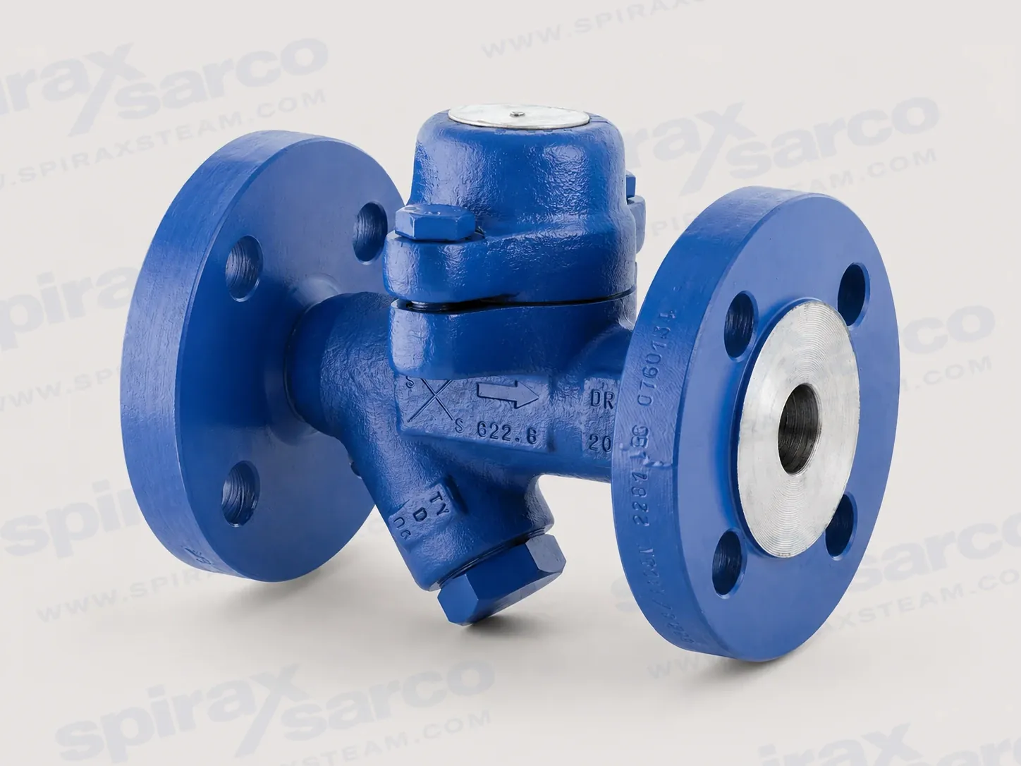
BPC32Y is a maintainable carbon steel balanced pressure thermostatic steam trap with straight connections and an integral cylindrical Y-type strainer for documented steam, air and water/condensate service.
BPC32Y balanced pressure thermostatic steam trap with Y-type strainer
Spirax Sarco BPC32Y is a carbon steel, maintainable balanced pressure thermostatic steam trap for removing condensate from steam systems. It has straight connections and an integral cylindrical Y-type strainer in the body. Combining the trap and its first filtration stage in one serviceable assembly makes the model useful where the trap must be inspected, cleaned and returned to service as part of routine plant maintenance.
The BPC32Y is intended for a defined engineering duty rather than an unqualified range of fluids. The installation information identifies steam, air and water or condensate in Group 2 applications as the documented fluid boundary. Material compatibility, pressure, temperature, differential pressure and return-line conditions must be checked together before the final configuration is selected.
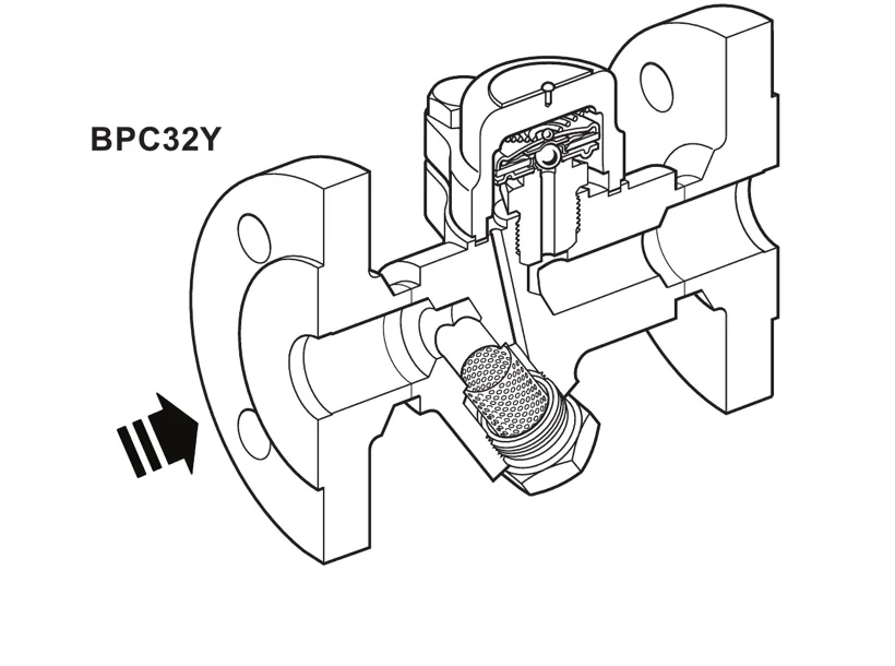
Official BPC32Y cutaway showing the straight flow path, operating capsule and removable cylindrical Y-type strainer.
How the BPC32Y balanced pressure trap operates
A balanced pressure thermostatic trap uses a capsule containing a small quantity of special liquid with a boiling point below that of water. In cold start-up conditions the capsule is relaxed, the valve is off its seat and the passage is open. Air and cold condensate can therefore leave the system without relying on a separate air-vent mechanism. This start-up response is one reason the balanced pressure principle is suitable for steam equipment that needs effective air removal.
As condensate approaches steam temperature, heat transfers into the capsule. The fill liquid boils, its vapour pressure expands the capsule and the valve closes. When the surrounding water cools, the fill condenses, the capsule contracts and the valve opens again to discharge condensate. The cycle is governed by the thermal condition around the capsule, not by a fixed open orifice.
The capsule fill changes the approximate discharge temperature relationship. The standard STD fill operates at about 12 °C below steam saturation temperature. A SUB fill operates at about 24 °C below saturation, while an NTS fill operates at about 6 °C below steam temperature. The fill must be stated when ordering because it affects the way the trap responds to condensate temperature and the amount of sub-cooling retained in the equipment.
The technical source describes the trap as unaffected by waterhammer. That documented statement does not replace correct pipework design. The inlet arrangement, drainage point, support, isolation, discharge route and return-line pressure still need to be reviewed as one system. The trap should be selected for the actual condensate load and available pressure difference at normal operation, start-up, shutdown and low-load conditions.
Integral cylindrical Y-type strainer and serviceable construction
The BPC32Y places a cylindrical Y-type strainer at the lower part of the body. The screen is accessed through the strainer cap and can be cleaned or replaced without treating the complete trap as a disposable unit. The capsule, spacer plate, valve seat, spring and cover are also serviceable. This arrangement gives maintenance teams a defined route for removing dirt from the first filtration stage and checking the operating assembly.
The main pressure-containing parts are carbon steel. The capsule, valve seat, screen, spring and spacer plate are stainless steel, and the source identifies AISI 304 stainless steel for the strainer screen. The cover uses a stainless steel reinforced exfoliated graphite gasket, while the M10 x 30 A2-70 cover bolts and the BS 1449 304 S16 strainer-cap gasket are also listed. These material designations support procurement and maintenance checks, but the final suitability review must still consider the process fluid, corrosion environment and temperature.
The Y-type screen is an integral component of the BPC32Y, not a substitute for every upstream filtration requirement. When the connected system needs a separate line filter for dirt management or equipment protection, compare the duty with the available steam strainer arrangements. The separate filtration device and the trap's integral screen have different service roles and should not be treated as interchangeable.
Pressure, temperature and condensate-duty selection
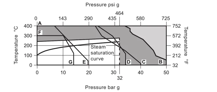
The BPC32Y has a PN40 body design condition. Its maximum allowable pressure is 50 bar g at 50 °C and its maximum allowable temperature is 400 °C at 35 bar g. For saturated steam service, the maximum operating condition is 32 bar g at 281 °C. The minimum allowable temperature is -60 °C and the minimum operating temperature is 0 °C; the source advises consultation for lower operating temperatures.
These values describe connected pressure and temperature conditions, not two independent maxima that can be combined without checking the chart. The official pressure and temperature envelope must be used with the applicable connection boundary. The 75 bar g cold hydraulic test value is a test limit, not an operating rating. Full-vacuum use is verified for the documented screwed, socket-weld, butt-weld and flanged connections; other arrangements require confirmation.
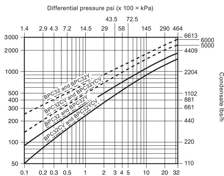
Capacity depends on the pressure difference available to drive condensate through the trap and on the condensate condition. Read the official capacity chart at the actual differential pressure and use the curve appropriate to the BPC32Y duty. A nominal pipe size is not a capacity value. The final review should include the equipment heat load, start-up load, operating pressure, return pressure, expected sub-cooling and any safety factor required by the plant standard.
Connections, application and ordering checks
The documented connection sizes are 1/2 inch, 3/4 inch and 1 inch, with DN15, DN20 and DN25 flange sizes. The connection families include screwed BSP T Rp (ISO 7-1) or NPT, socket weld ends to BS 3799, butt weld ends to EN 12 627, and flanged arrangements to EN 1092 PN40, ASME B 16.5 Class 150 or Class 300, and JIS/KS 10K or 20K. Select the connection standard to match the pipework and local installation practice; do not infer a connection standard from nominal size alone.
For a wider selection review of Spirax Sarco BPC32Y, the steam trap selection resource helps place a balanced pressure thermostatic trap in the wider condensate-removal system. The BPC32Y is appropriate only when its documented pressure and temperature envelope, capsule response, condensate load and installation arrangement match the duty. If the system includes a rising return line or other condensate backpressure, plan the downstream protection during selection.
Before an order is released, record the model, size, connection standard, capsule fill, normal and maximum pressure, temperature, condensate load, available differential pressure, return-line backpressure and discharge arrangement. State certification and inspection requirements at order placement; EN 10204 3.1 certification is available when requested. This information gives the selected configuration a traceable engineering basis.
Installation integration and safe discharge
The installation guide permits the BPC32Y to be installed horizontally or vertically when the installation situation and direction of fluid flow are correct. A drop leg immediately before the trap is preferred, typically 150 mm (6 inches), because a low-load steam flow can pass over condensate in the bottom of a pipe if the drop leg is omitted. Upstream and downstream isolation valves provide the controlled boundary needed for inspection, screen cleaning and replacement.
Where condensate enters a return line with backpressure, fit a downstream steam check valve so the steam space cannot flood when inlet pressure falls or steam is shut off. Where the trap discharges to atmosphere, direct the outlet to a safe location. The source strongly recommends a steam diffuser to cushion high-velocity discharge and reduce noise and erosion. The discharge may be at 100 °C, so access and guarding must be planned for hot fluid.
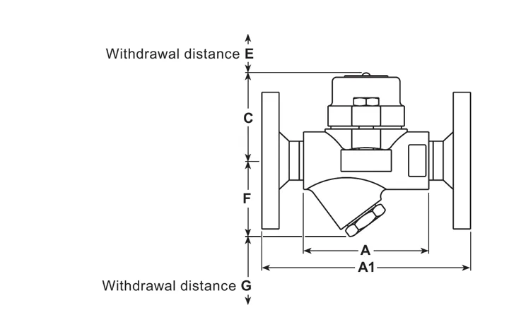
Leave at least 37 mm of cover withdrawal space and 28 mm of screen withdrawal space for BPC32Y maintenance. These clearances are part of the installed arrangement, not an optional convenience. Confirm that personnel can reach the strainer cap and cover without exposure to uncontrolled pressure, hot surfaces or hazardous process residue.
Maintenance and BPC32Y specification summary
Maintenance can be completed with the BPC32Y in the pipeline only after the supply and return sides have been isolated, pressure has safely normalised to atmosphere and the trap has cooled. Keep joint faces clean during reassembly and use suitable tools, protective equipment and appropriate replacement parts. For the Y-type screen, remove the strainer cap and screen, clean or replace the screen as required, centre it during reassembly and fit a new cap gasket where recommended. Apply a small amount of anti-seize to the threads and tighten to the documented torque.
Carbon steel maintainable balanced pressure thermostatic steam trap with straight connections and an integral cylindrical Y-type strainer.
STD, SUB and NTS capsule fills for different approximate discharge-temperature relationships.
1/2 inch, 3/4 inch and 1 inch sizes with documented screwed, welded and flanged connection families.
PN40 body design condition, 32 bar g at 281 °C maximum saturated-steam operating condition and 75 bar g maximum designed cold hydraulic test pressure.
Horizontal or vertical installation with correct flow direction, a preferred 150 mm drop leg, return-line protection where backpressure occurs and safe atmospheric discharge.
When specifying Spirax Sarco BPC32Y, retain the process data, connection standard, capsule fill, screen-access clearance and certification requirement with the model reference. The technical information and installation and maintenance sections that follow provide the detailed tables, diagrams, safety conditions and service sequence for final review.
Description
The BPC32Y is a carbon steel maintainable balanced pressure thermostatic steam trap with straight connections and an integral cylindrical Y-type strainer. All pressure-bearing components are produced by TÜV-approved suppliers in accordance with AD-Merkblatt WO/TRD100. The trap is unaffected by waterhammer.
Capsule fill and operation
Fill
Documented operation
STD
Approximately 12 °C (53.6 °F) below steam saturation temperature.
SUB
Approximately 24 °C (75.2 °F) below steam saturation temperature.
NTS
Approximately 6 °C (42.8 °F) below steam temperature.
Always state the capsule fill when placing an order.
Standards
This product fully complies with the requirements of the European Pressure Equipment Directive 2014/68/EU.
Certification
Certification to EN 10204 3.1 is available. State all certification and inspection requirements at the time of order placement.
Sizes and pipe connections
1/2 inch, 3/4 inch and 1 inch screwed BSP T Rp (ISO 7-1) or NPT.
1/2 inch, 3/4 inch and 1 inch socket weld ends to BS 3799.
1/2 inch, 3/4 inch and 1 inch butt weld ends to EN 12 627.
DN15, DN20 and DN25 standard flange to EN 1092 PN40, ASME B 16.5 Class 150 and 300, and JIS/KS 10K and 20K.
Pressure/temperature limits (ISO 6552)
Read pressure and temperature together. Do not operate in the prohibited regions or beyond the applicable connection boundary.
PMO maximum operating pressure for saturated steam service
32 bar g at 281 °C (464 psi g at 537 °F)
TMO maximum operating temperature
281 °C at 32 bar g (538 °F at 464 psi g)
Minimum operating temperature
0 °C (32 °F); consult Spirax Sarco for lower operating temperatures
Full vacuum
Verified safe for screwed, socket weld, butt weld and flanged connections; confirm other arrangements with Spirax Sarco
Maximum cold hydraulic test pressure
75 bar g (1088 psi g)
Materials
No.
Part
Material
1
Cover
Carbon steel DIN 17243 C22.8 (W/S 1.0460), ASTM A105N
2
Capsule
Stainless steel
3
Valve seat
Stainless steel BS 970 431 S29
5
Strainer screen
Stainless steel AISI 304
7
Cover gasket
Stainless steel reinforced exfoliated graphite
8
Body
Carbon steel DIN 17243 C22.8 (W/S 1.0460), ASTM A105N
9
Cover bolts
Stainless steel M10 x 30, A2-70
10
Strainer cap
Carbon steel DIN 17243 C22.8 (W/S 1.0460), ASTM A105N
11
Strainer cap gasket
Stainless steel BS 1449 304 S16
17
Spring
Stainless steel
18
Spacer plate
Stainless steel
Dimensions and weights
Dimension drawing for the BPC32Y body; dimensions are approximate and the letters correspond to the table below.
Size
A
A1
B
C
D
E
F
G
Weight screwed/SW/BW
Weight flanged
1/2 inch DN15
95 (3.74)
150 (5.9)
94 (3.70)
64 (2.52)
-
37 (1.46)
54 (2.13)
28 (1.10)
1.6 kg (3.5 lb)
3.1 kg (6.8 lb)
3/4 inch DN20
95 (3.74)
150 (5.9)
94 (3.70)
64 (2.52)
-
37 (1.46)
54 (2.13)
28 (1.10)
1.6 kg (3.5 lb)
3.7 kg (8.2 lb)
1 inch DN25
95 (3.74)
150 (5.9)
94 (3.70)
64 (2.52)
-
37 (1.46)
54 (2.13)
28 (1.10)
1.8 kg (4.0 lb)
4.4 kg (9.7 lb)
Dimensions are in mm with inch equivalents in parentheses. Weights are approximate.
Capacities
The official chart is a shared source graph. Use the BPC32Y curve with the actual differential pressure and condensate condition; nominal connection size is not a capacity value.
Safety information, installation and maintenance
For full safety, installation, commissioning, operation and maintenance details, see the Installation and Maintenance Instructions IM-P005-02 supplied with the product.
Installation note
The BPC32Y may be installed in any position, horizontal or vertical, with the direction of fluid flow correctly established. Fit a downstream non-return valve where backpressure is experienced in a condensate return line. Fit a diffuser when discharging to atmosphere, and consider upstream and downstream isolation valves to make maintenance easier.
Disposal
The product is recyclable. No ecological hazard is anticipated when it is disposed of with due care and in accordance with local requirements.
How to order
Example: 1 off Spirax Sarco 1/2 inch BPC32Y carbon steel-bodied maintainable balanced pressure thermostatic steam trap, screwed BSP with an STD fill capsule for operation at approximately 12 °C (53.6 °F) below steam saturation temperature.
Spare parts
The following spare parts are applicable to the BPC32Y:
Available spare
Item
Capsule and seat assembly set
2, 3, 17, 18
Strainer screen and gasket, 1 off each
5, 11
Set of cover gaskets, packet of 3
7
Strainer cap gasket, packet of 3
11
Order spares using the description in the available-spares list and state the size, model number and capsule reference.
Recommended tightening torques
Item
Part
Tool
Torque
3
Valve seat
24 A/F
115-125 N m (82-89 lbf ft)
9
Cover bolts
16 A/F, M10 x 30
23-27 N m (16-19 lbf ft)
10
Strainer cap
27 A/F
120-135 N m (86-96 lbf ft)
Installation and Maintenance Guide
Safety information
General product information
Installation
Commissioning
Operation
Maintenance
Spare parts
This guide applies to the BPC32Y balanced pressure thermostatic steam trap. Read it with the applicable Technical Information Sheet and the product name-plate before installation, commissioning or maintenance.
1. Safety information
Safe operation of the BPC32Y can only be guaranteed if it is properly installed, commissioned, used and maintained by qualified personnel in compliance with these instructions. General installation and safety instructions for pipeline and plant construction, together with the proper use of tools and safety equipment, must also be followed.
1.1 Intended use
Use this guide, the name-plate and the Technical Information Sheet to confirm that the BPC32Y is suitable for the intended application. The product complies with the European Pressure Equipment Directive 2014/68/EU and is classified as SEP for Group 2 gases and Group 2 liquids.
The product is designed for steam, air or water/condensate in Group 2. Other fluids require confirmation of suitability.
Check material suitability, pressure and temperature, including maximum and minimum values. If the product limits are lower than the system limits, provide a safety device to prevent overpressure or overtemperature.
Determine the correct installation situation and direction of fluid flow.
Consider external stresses induced by the connected system and take precautions to minimise them.
Remove protection covers from connections and protective film from name-plates where appropriate before high-temperature service.
1.2 Access and lighting
Ensure safe access and, where necessary, a suitably guarded working platform before working on the product. Arrange suitable lifting gear if required. Provide adequate lighting, particularly where detailed or intricate work is required.
1.3 Hazardous liquids or gases
Consider what is in the pipeline or what may have been in it previously, including flammable materials, substances hazardous to health and extremes of temperature.
1.4 Hazardous environment
Consider explosion risk areas, lack of oxygen, dangerous gases, extremes of temperature, hot surfaces, fire hazards during welding, excessive noise and moving machinery.
1.5 The system
Consider the effect of the proposed work on the complete system. Closing isolation valves or isolating equipment must not put other plant or personnel at risk. Isolation valves should be opened and closed gradually to avoid system shocks.
1.6 Pressure systems
Isolate pressure and safely vent it to atmospheric pressure. Consider double isolation with block and bleed, and lock or label closed valves. Never assume that a system is depressurised because a pressure gauge reads zero.
1.7 Temperature
Allow time for temperature to normalise after isolation to avoid burns.
1.8 Tools and consumables
Use suitable tools and consumables, and use only genuine replacement parts.
1.9 Protective clothing
Assess whether personnel require protection against chemicals, high or low temperature, radiation, noise, falling objects and eye or face hazards.
1.10 Permits to work
All work must be carried out or supervised by a suitably competent person. Installation and operating personnel should be trained in correct use. Follow a formal permit-to-work system where one exists; otherwise ensure that a responsible person knows what work is in progress and arrange assistance where necessary. Post warning notices if required.
1.11 Handling
Assess manual-handling risks by considering the task, individual, load and working environment. Use suitable methods for lifting, pushing, pulling, carrying or supporting the product.
1.12 Residual hazards
The external surface may be very hot in normal use and may exceed 250 °C (482 °F) at maximum permitted conditions. The product is not self-draining. Take care when dismantling or removing it from an installation.
1.13 Freezing
Protect the product against frost damage where it may be exposed to temperatures below freezing point.
1.14 Disposal
The product is recyclable and no ecological hazard is anticipated when it is disposed of with due care. Check current compliance information and local recycling and disposal regulations.
1.15 Returning products
When returning the product, provide written information about hazards and precautions required because of contamination residues or mechanical damage, including health and safety data sheets for hazardous or potentially hazardous substances.
2. General product information
2.1 Description
The BPC32Y is a carbon steel maintainable balanced pressure thermostatic steam trap with straight connections and an integral cylindrical Y-type strainer. All pressure-bearing components are produced by TÜV-approved suppliers in accordance with AD-Merkblatt WO/TRD100. The trap is unaffected by waterhammer.
The standard capsule is marked STD and operates at approximately 12 °C (21.6 °F) below steam saturation temperature. A SUB capsule operates at approximately 24 °C (43.2 °F) below steam saturation temperature, and an NTS capsule operates at approximately 6 °C (10.8 °F) below steam temperature. Always state the capsule fill when ordering.
The product complies with the European Pressure Equipment Directive 2014/68/EU. Certification to EN 10204 3.1 is available when requested, and all certification or inspection requirements must be stated at the time of order placement.
2.2 Sizes and pipe connections
1/2 inch, 3/4 inch and 1 inch screwed BSP T Rp (ISO 7-1) or NPT.
1/2 inch, 3/4 inch and 1 inch socket weld ends to BS 3799.
1/2 inch, 3/4 inch and 1 inch butt weld ends to EN 12 627.
DN15, DN20 and DN25 flanged connections to EN 1092 PN40, ASME B 16.5 Class 150 and 300, and JIS/KS 10K and 20K.
Use the Technical Information Sheet and the product name-plate for the complete pressure and temperature limits of the selected connection configuration.
3. Installation
Before installation, observe the safety information in Section 1. Refer to the name-plate and Technical Information Sheet and check that the BPC32Y is suitable for the intended installation.
3.1 Check system limits. Check materials, pressure and temperature and their maximum values. If the maximum operating limit of the product is lower than the system limit, include a safety device to prevent overpressurisation.
3.2 Confirm flow. Determine the correct installation situation and the direction of fluid flow.
3.3 Remove protection. Remove protective covers from connections and protective film from name-plates where appropriate before installation on steam or other high-temperature applications.
3.4 Provide a drop leg. The trap may be installed in any position, horizontal or vertical, preferably with a drop leg immediately preceding it, typically 150 mm (6 inches). Without a drop leg, low-load steam may flow over condensate in the bottom of the pipe and reach the trap.
3.5 Protect return lines. Fit a downstream non-return valve when discharging into a condensate return line where backpressure is experienced. This prevents the steam space flooding when inlet pressure is reduced or steam is shut off.
3.6 Control atmospheric discharge. When discharging to atmosphere, install a diffuser on the outlet side to cushion high-velocity discharge and reduce noise and erosion. Discharge to a safe place because the fluid may be at 100 °C (212 °F).
3.7 Install isolation valves. Provide isolation valves for safe maintenance and trap replacement.
3.8 Open slowly. Open isolation valves slowly until normal operating conditions are achieved.
3.9 Check operation. Check for leaks and correct operation.
3.10 Allow maintenance clearance. Leave adequate space to remove the cover from the body. The minimum cover withdrawal distance is 37 mm (1 1/2 inches), and the minimum withdrawal distance for the Y-type strainer screen is 28 mm (1 1/8 inches).
3.11 Welding into the pipeline. It is not necessary to remove the operating capsule when welding by the electric arc method. Consult the relevant national and international welding standards for specific procedures.
4. Commissioning
After installation or maintenance, ensure that the system is fully functional. Test any alarms or protective devices.
5. Operation
The operating element is a capsule containing a small quantity of special liquid with a boiling point below that of water. In the cold conditions at start-up, the capsule is relaxed, the valve is off its seat and the passage is wide open, allowing unrestricted removal of air. This is a feature of balanced pressure traps.
As condensate passes through the trap, heat transfers to the capsule liquid. The fill liquid boils before steam reaches the trap, and vapour pressure in the capsule causes it to expand and close the trap. Heat loss then cools the water around the capsule, the fill condenses and the capsule contracts. The valve opens to release condensate until steam temperature is approached and the cycle repeats.
6. Maintenance
Observe the safety information before starting maintenance.
Warning: The cover gasket contains a thin stainless steel support ring that may cause physical injury if it is not handled and disposed of carefully.
6.1 General information
Isolate the BPC32Y from both the supply and return lines. Allow pressure to safely normalise to atmosphere and allow the trap to cool. Ensure that joint faces are clean during reassembly. Maintenance may be completed with the trap in the pipeline after these safety procedures have been observed. Use new gaskets and genuine spares where required, suitable tools and necessary protective equipment. When maintenance is complete, open isolation valves slowly and check for leaks.
6.2 Fit a new capsule and seat
Remove the cover (1) and spring (17) from the body (8) by unscrewing the two cover bolts (9).
Remove the capsule (2) and spacer plate (18).
Unscrew the valve seat (3) from the body (8).
Replace the valve seat (3) and tighten it to the recommended torque.
Fit a new cover gasket (7) where required. Reassemble the spacer plate (18), ensuring that it is centred on the valve seat (3).
Reassemble the capsule (2), spring (17) and cover (1). Progressively tighten the cover bolts (9) to the recommended torque.
6.3 Clean or replace the Y-type strainer screen
Undo the strainer cap (10) and remove the strainer screen (5).
Clean or replace the screen as required.
Reassemble the strainer cap (10) into the body (8), ensuring that the screen (5) is located centrally. Fit a new strainer-cap gasket (11) where recommended.
Apply a small amount of anti-seize compound to the threads and tighten the strainer cap to the recommended torque.
Table 1. Recommended tightening torques
Item
Part
Tool
Torque
3
Valve seat
24 A/F
115-125 N m (82-89 lbf ft)
9
Cover bolts
16 A/F, M10 x 30
23-27 N m (16-19 lbf ft)
10
Strainer cap
27 A/F
120-135 N m (86-96 lbf ft)
7. Spare parts
Order spares using the description in the available-spares list and state the size, model number and capsule reference.
Available spare for BPC32Y
Item
Capsule and seat assembly set
2, 3, 17, 18
Y-type strainer screen and gasket, 1 off each
5, 11
Set of cover gaskets, packet of 3
7
Strainer-cap gasket, packet of 3
11
State the selected capsule reference, such as STD, SUB or NTS, when ordering a capsule and seat assembly set.