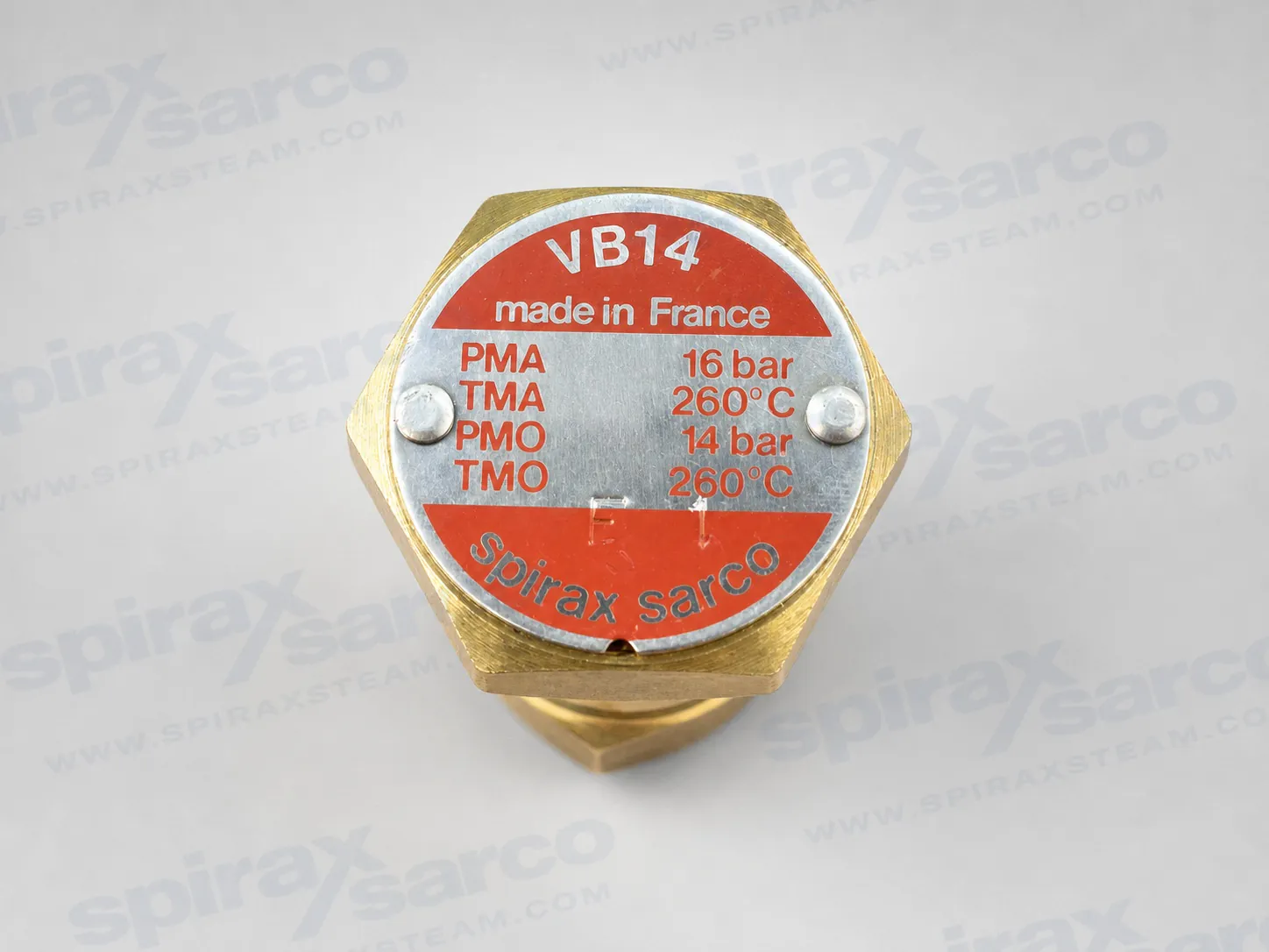
VB14 Vacuum Breaker
The Spirax Sarco VB14 is a compact brass vacuum breaker for condensing steam and liquid systems. It admits air as equipment cools to prevent vacuum from restricting condensate drainage and operation.

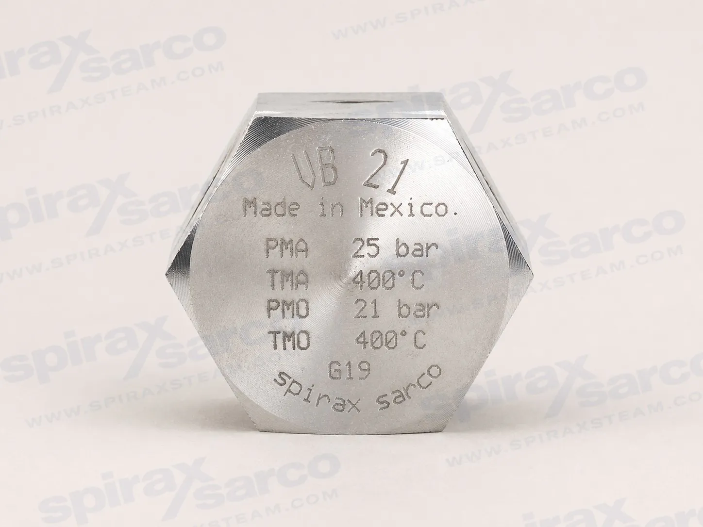
VB21
VB21 Stainless Steel Vacuum Breaker
Compact stainless steel vacuum breaker for condensing steam, vapour and liquid systems, with 1/2 inch BSP or NPT connections and operation up to 21 barg.
The Spirax Sarco VB21 vacuum breaker is a compact, purpose-designed stainless steel unit for general-purpose condensing vapour, steam and liquid systems. Its role is straightforward but important: when pressure inside the connected system falls below the pressure at the air inlet, the valve opens to admit air. This replaces volume lost as vapour condenses and helps prevent a vacuum from developing in pipework or storage vessels. During normal positive-pressure operation, the precision-ground valve remains seated to provide tight shut-off.
This operating principle makes the VB21 relevant wherever a closed space can cool after steam service or another condensing duty. Steam occupies much less volume after it becomes condensate, so system pressure can fall quickly unless air is allowed to enter at the correct point. By responding automatically at the onset of vacuum, the VB21 supports effective condensate drainage and protects the connected system from the consequences of an unwanted pressure differential.
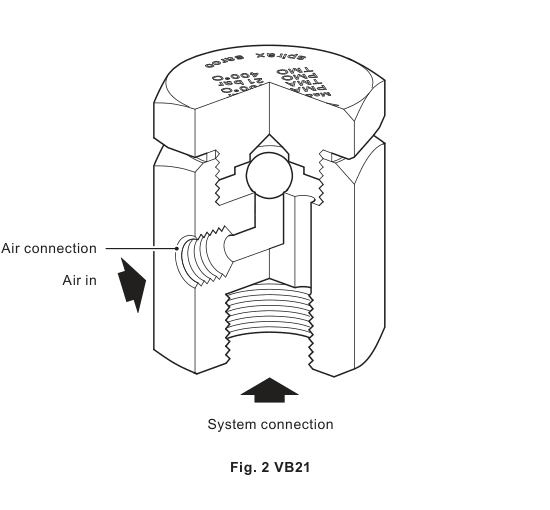
Under normal operating conditions, pressure in the system is higher than pressure at the atmospheric air connection. That pressure relationship holds the stainless steel valve firmly against its seat. As steam cools and begins to condense, the pressure in the upper chamber falls. The valve remains seated until the chamber pressure drops below the air inlet pressure, which is normally atmospheric pressure. At that point the valve lifts, and air passes through the upper chamber into the system.
The response threshold is deliberately low: the published differential pressure required to open the vacuum breaker is 4.6 mm Hg. The technical information also gives a Kv value of 0.52 and provides an air-flow capacity curve across a range of differential pressures. These figures should be used together rather than treated as isolated claims. The opening differential describes when the valve begins to respond, while the capacity curve relates the available air flow to the differential pressure once flow develops.
When positive system pressure is restored, the pressure relationship changes and the valve returns to its seat. Shut-off conforms to EN 12266-1 Rate E. The action is entirely mechanical, so correct selection and installation determine whether the air path is available when needed and remains closed during normal service.
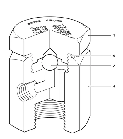
The VB21 uses stainless steel throughout its principal pressure-containing and moving parts. The published material schedule identifies an AISI 303 stainless steel cap and body, an AISI 440 C stainless steel valve and an AISI 304 stainless steel gasket. Within the vacuum breaker range, this construction distinguishes the standard VB21 from brass-bodied alternatives while giving the engineer a defined material basis for compatibility review.
Material identity alone does not establish suitability for every process fluid. The installation instructions define the standard service boundary as steam, air and water or condensate in Group 2 service. If another fluid is proposed, suitability should be confirmed with Spirax Sarco before the valve is selected. The standard VB21 should also not be assumed to carry the food-contact declarations associated with a separately designated variant; certification and compliance requirements must be tied to the exact ordered product.
The product complies with the applicable requirements of the EU Pressure Equipment Directive and the UK Pressure Equipment (Safety) Regulations. It is classified as SEP for Group 2 gas and liquid service in the installation instructions. A manufacturer's Typical Test Report is available, provided the requirement is stated when the order is placed. These documents support procurement and project records, but they do not replace checking the actual system design conditions.
The system connection is 1/2 inch screwed BSP or NPT, while the atmospheric air inlet is a separate 1/8 inch screwed BSP or NPT connection. Thread form must be selected deliberately: nominal size does not make BSP and NPT threads interchangeable. The published ordering example specifies a 1/2 inch BSP unit, and the current product record also identifies material code 0190195 for that configuration. NPT availability should be confirmed as part of order placement.
The VB21 is physically compact. For the 1/2 inch size, the technical information gives an approximate overall dimension A of 52 mm, with B and C both 36 mm; dimension B is the across-flats value. Approximate product weight is 0.33 kg. These dimensions help with layout and tool-access checks, although the surrounding pipework still needs enough space for installation, inspection and complete-unit replacement.
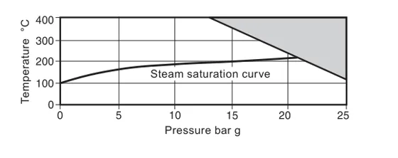
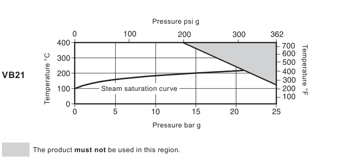
The body is designed to PN25 conditions. Maximum allowable pressure is 25 barg at 120 °C, while the maximum allowable temperature is 400 °C at 13 barg. For operation, the maximum saturated-steam pressure is 21 barg and the maximum operating temperature is 400 °C at 13 barg. Minimum operating temperature is 0 °C, and the maximum cold hydraulic test pressure is 38 barg.
These values describe points on a pressure-temperature envelope; they are not independent maximums that can be combined freely. A proposed operating point must remain within the published envelope and outside its prohibited region. The minimum allowable material temperature of -48 °C is likewise not the normal minimum operating temperature. For operation below 0 °C, the manufacturer should be consulted. Where the surrounding installation may fall below freezing, the installation also needs appropriate protection, particularly if the arrangement is not self-draining.
Selection should account for both steady operating conditions and credible transients. If the system can exceed the valve's pressure or temperature limits, a suitable protective device is required. The pressure rating of the valve does not remove the need to check the vessel, pipework, joints and every other connected component against the same design case.
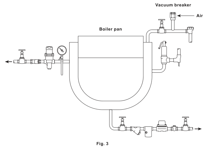
The documented application is general-purpose service on condensing vapour, steam or liquid systems. In practical selection terms, the system must have a location where admitting air can prevent vacuum and where that air can reach the space being protected. On steam systems, the technical information calls for installation at the highest point where the valve will not be flooded with condensate. Flooding the air path or placing the product where air cannot reach the relevant volume undermines the intended function.
The VB21 is installed vertically with its 1/2 inch system connection at the bottom. The 1/8 inch inlet communicates with atmosphere and must remain unobstructed. Its discharge or inlet piping must be directed to a safe place because fluid released from the connection can reach 100 °C. Connected pipework should be supported so that external loads are not transferred into the valve body.
These requirements are more than layout preferences. Vertical mounting establishes the intended relationship between the internal valve, seat and system connection. A high-point location reduces the risk of the unit being flooded by condensate, and an open, safely routed atmospheric connection preserves the pressure reference that makes the valve operate. The detailed installation guide should therefore be reviewed during design as well as before site work begins.
The VB21 is a non-maintainable product. It has no serviceable internal components, and no spare parts are available. If it does not close correctly under positive pressure or fails to admit air as system pressure falls, the complete unit must be replaced. This simplifies the parts decision but makes isolation, access and replacement planning important at the design stage.
Before removal, the connected system has to be isolated, depressurised and allowed to cool. Residual fluid may remain because the installation may not be self-draining. A replacement must match the required pressure capability and thread standard, and any certification requirement should be restated with the new order. The product is recyclable when handled in accordance with applicable local requirements and current product-compliance guidance.
A complete selection starts with the process duty, not only the model code. Confirm that the intended medium is within the documented service scope, then establish the maximum and minimum pressure-temperature cases. Check the 1/2 inch BSP or NPT system connection, the corresponding 1/8 inch atmospheric connection, the vertical mounting position, high-point location and safe air path. Allow physical access for installation and future whole-unit replacement.
Finally, state the exact thread form and any test-report or inspection requirement at order placement. For the listed 1/2 inch BSP configuration, material code 0190195 provides a precise purchasing reference. Using the full specification avoids ambiguity between thread standards or between the standard VB21 and separately designated variants. The technical information and installation guide that follow provide the dimensional, operating-envelope, capacity, safety and installation details needed to complete that review.
The VB21 is a small, purpose-designed vacuum breaker for general-purpose applications on condensing vapour (steam) or liquid systems.
The product complies with the requirements of the EU Pressure Equipment Directive and the UK Pressure Equipment (Safety) Regulations. Shut-off conforms to EN 12266-1 Rate E.
A manufacturer's Typical Test Report is available. State all certification and inspection requirements when placing the order.
| No. | Part | Material | Designation |
|---|---|---|---|
| 1 | Cap | Stainless steel | AISI 303 |
| 2 | Valve | Stainless steel | AISI 440 C |
| 4 | Body | Stainless steel | AISI 303 |
| 5 | Gasket | Stainless steel | AISI 304 |
| Connection | Size | Form |
|---|---|---|
| System connection | 1/2 inch | Screwed BSP or NPT |
| Air inlet connection | 1/8 inch | Screwed BSP or NPT |
| Body design conditions | PN25 |
|---|---|
| PMA, maximum allowable pressure | 25 barg at 120 °C |
| TMA, maximum allowable temperature | 400 °C at 13 barg |
| Minimum allowable temperature | -48 °C |
| PMO, maximum operating pressure for saturated steam service | 21 barg |
| TMO, maximum operating temperature | 400 °C at 13 barg |
| Minimum operating temperature | 0 °C |
| Maximum cold hydraulic test pressure | 38 barg |
For operation below 0 °C, consult Spirax Sarco. Pressure and temperature limits are related points on the published envelope and must not be treated as independently interchangeable ratings.
The differential pressure required to open the vacuum breaker is 4.6 mm Hg.
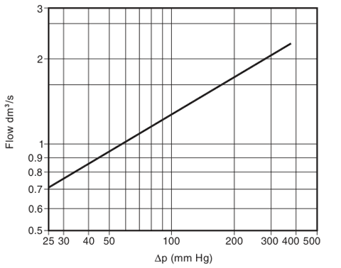
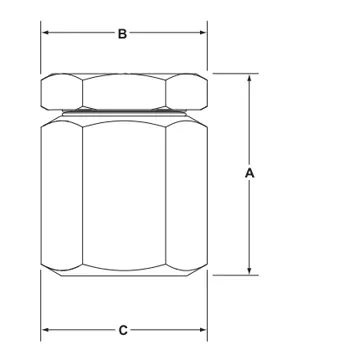
Approximate dimensions are in millimetres and weight is in kilograms.
| Size | A | B (A/F) | C | Kv | Weight |
|---|---|---|---|---|---|
| 1/2 inch | 52 | 36 | 36 | 0.52 | 0.33 kg |
Install the VB21 vertically with the system connection at the bottom. On steam systems, position the vacuum breaker at the highest point in the system where it will not be flooded with condensate. Refer to IM-P019-05 for complete safety, installation and maintenance instructions.
Ordering example: 1 off Spirax Sarco VB21 vacuum breaker having 1/2 inch screwed BSP connections.
This conversion retains the portions of IM-P019-05 that apply to the standard VB21: intended use, construction, connections, operating limits, installation, commissioning, operating sequence, maintenance and essential safety requirements. Material specific only to other models has been excluded.
Check the Installation and Maintenance Instructions, product nameplate and applicable technical information before use. The VB21 is designed for steam, air and water or condensate in Group 2 service. Use with another fluid may be possible only after Spirax Sarco confirms suitability for the proposed application.
| Product | Group 1 gases | Group 2 gases | Group 1 liquids | Group 2 liquids |
|---|---|---|---|---|
| VB21 | - | SEP | - | SEP |
The product complies with the requirements of the EU Pressure Equipment Directive and the UK Pressure Equipment (Safety) Regulations. Products classified as SEP are not required to carry the directive mark.
The VB21 is a purpose-designed stainless steel vacuum breaker for general-purpose condensing vapour, steam or liquid systems at pressures up to 21 barg (304 psig). A manufacturer's Typical Test Report is available when requested at the time of order.
| Connection | Size and form |
|---|---|
| System connection | 1/2 inch screwed BSP or NPT |
| Air inlet connection | 1/8 inch screwed BSP or NPT |
Specify a consistent BSP or NPT connection form at order placement. Do not infer thread compatibility from nominal size alone.
| Body design conditions | PN25 |
|---|---|
| PMA, maximum allowable pressure | 25 barg at 120 °C (362 psig at 248 °F) |
| TMA, maximum allowable temperature | 400 °C at 13 barg (752 °F at 188 psig) |
| Minimum allowable temperature | -48 °C (-54 °F) |
| PMO, maximum operating pressure for saturated steam | 21 barg (304 psig) |
| TMO, maximum operating temperature | 400 °C at 13 barg (752 °F at 188 psig) |
| Minimum operating temperature | 0 °C (32 °F) |
| Maximum cold hydraulic test pressure | 38 barg (551 psig) |
The pressure and temperature limits are conditional points on the published envelope, not independent ratings that can be combined freely. The system operating point must remain outside the prohibited region shown above.
Observe the safety requirements before starting installation. Check the nameplate and confirm that the material, pressure and temperature limits suit the intended system.
Provide frost protection where a non-self-draining installation may be exposed below freezing. The published minimum operating temperature is 0 °C (32 °F), even though the allowable material limit extends lower.
After installation or maintenance, restore the system in a controlled manner and confirm that the complete plant functions correctly. Test any alarms and protective devices affected by the work. Check threaded joints under operating conditions and verify that the atmospheric inlet remains unobstructed.
The VB21 protects steam plant and process equipment against vacuum while allowing condensate to drain effectively from pipework and storage vessels. Its documented flow coefficient is Kv 0.52, and a differential pressure of 4.6 mm Hg is required to open the valve.
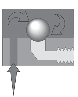
The precision-ground stainless steel valve is held firmly on its seat during normal operating conditions, providing tight shut-off while the system remains above the air inlet pressure.
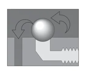
As steam begins to condense, system pressure falls. The valve remains on its upper seat until pressure in the upper chamber falls below the air inlet pressure, which is normally atmospheric pressure.
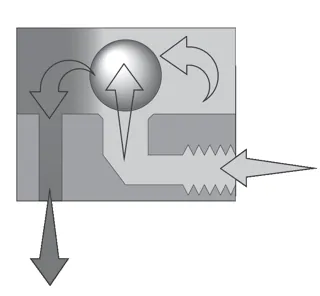
When a vacuum starts to form, the valve lifts immediately from its seat. Air is drawn through the upper chamber into the system, replacing the volume lost through condensation and preventing vacuum formation.
The VB21 is a non-maintainable product. It has no serviceable internal components and no spare parts are available. If the valve fails to close correctly under positive pressure or fails to admit air as system pressure falls, isolate the system and replace the complete unit.
Before removal, isolate all pressure and vent safely to atmosphere. Allow the unit to cool, then take care with residual fluid because the connected system may not be self-draining. Use a replacement with the correct pressure capability and thread standard, and restate any certification requirement when ordering.
The product is recyclable when handled with due care and in accordance with local recycling and disposal requirements. Review current Spirax Sarco product-compliance information for substances of concern. When returning a used unit, provide written details of hazardous contamination residues or mechanical damage, together with relevant safety data, so the product can be handled safely.