
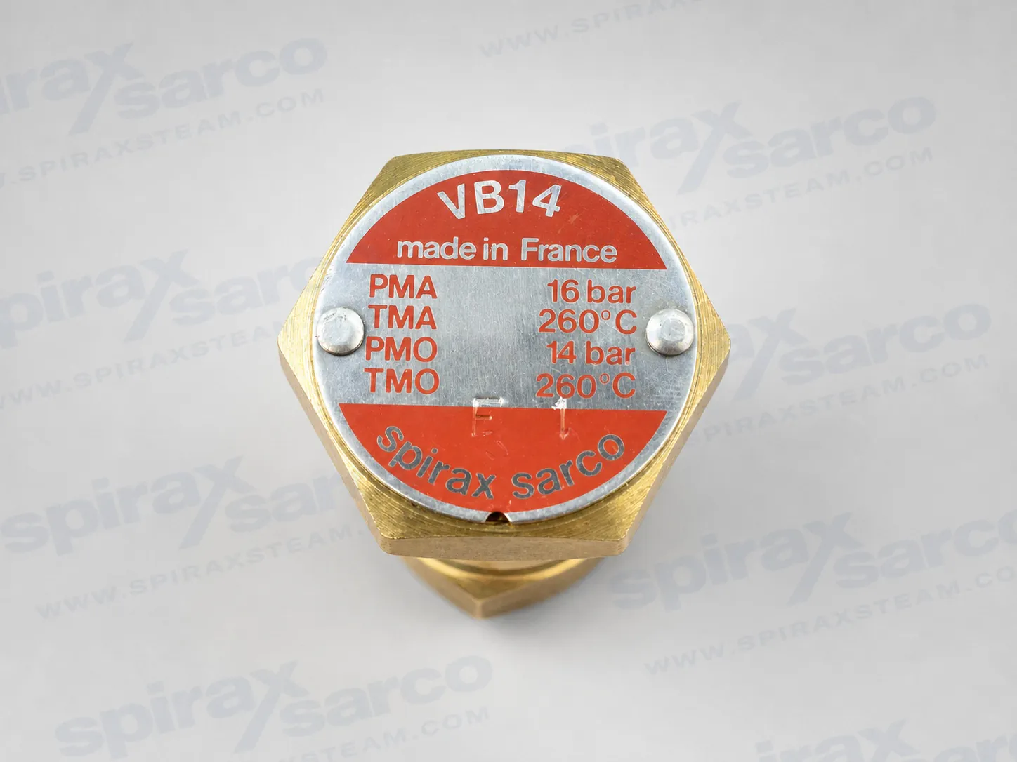
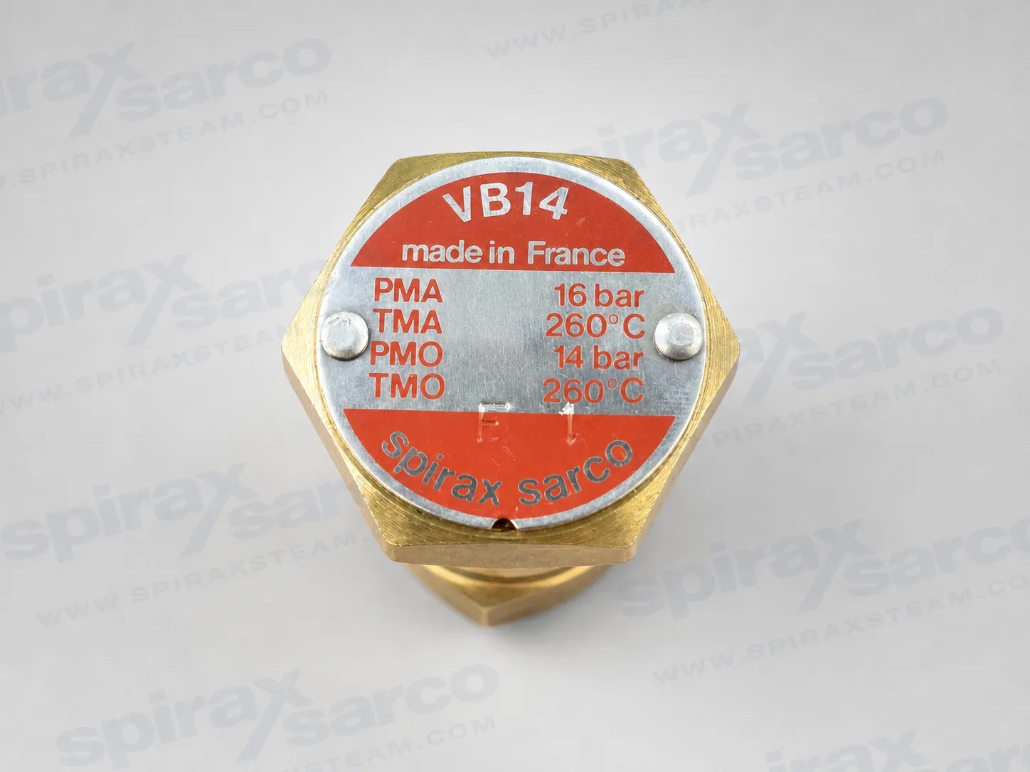
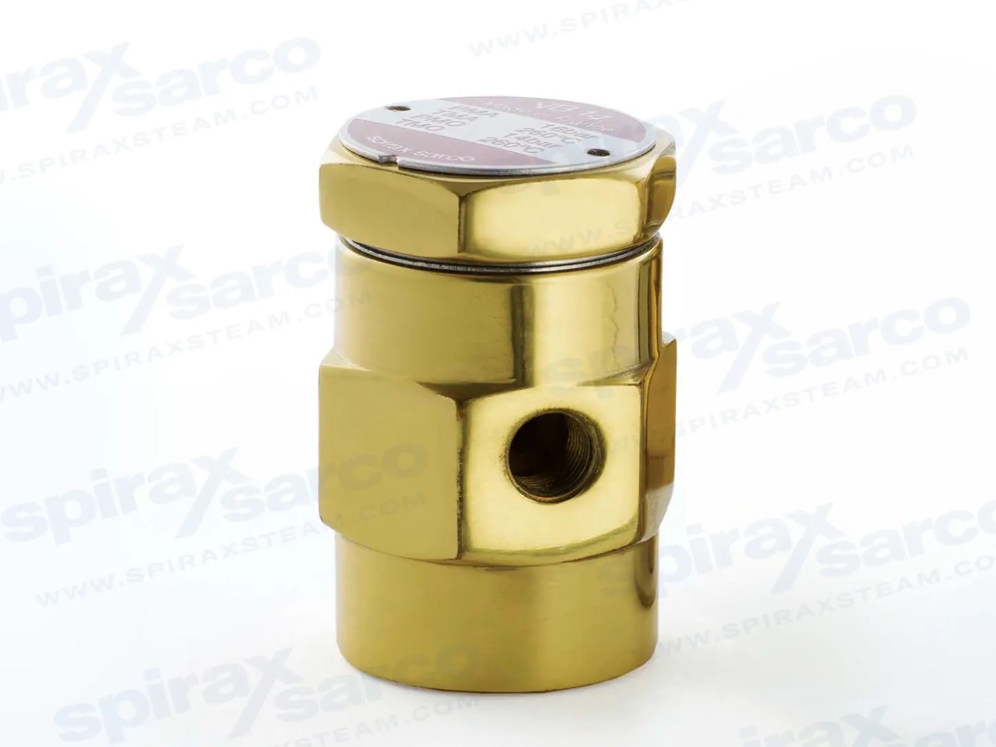
Spirax Sarco VB14 selection and use
The Spirax Sarco VB14 vacuum breaker is a compact brass device for condensing steam and liquid systems. When equipment cools after shutdown, steam condenses into a much smaller volume and can create vacuum. The VB14 admits air when the internal pressure falls below the air-inlet pressure, helping heat exchangers, coils, vessels and pipework drain and operate correctly.
The VB14 sits within the wider Spirax Sarco vacuum breaker range, but this page and its inquiry option cover the VB14 model only.
- Construction: Brass body and cover with stainless steel valve components.
- Duty: General-purpose vacuum protection for condensing vapour, steam and liquid systems.
- Connections: ½-inch system connection and ⅛-inch air inlet; BSP or NPT versions are available.
- Installation: Install vertically with the system connection at the bottom and the air inlet discharging to a safe location.
- Maintenance: The current installation guide identifies the VB14 as a non-maintainable product; replace the complete unit if it fails.
Product purpose and benefits
The VB14 is used on steam systems and heat exchangers that may retain steam after shutdown. As the vessel cools, condensate occupies far less volume than the original steam and vacuum conditions can develop. Admitting air prevents the vacuum from inhibiting drainage or equipment operation.
- Compact design for local installation.
- Brass pressure body.
- Stainless steel valve and seat.
- Vertical installation provides the intended operating orientation.
Sales-sheet pressure and temperature data
| Model | Maximum pressure | Temperature limit shown in datasheet 170007 |
|---|---|---|
| VB14 | 14 bar | 260 °C at 7 bar |
Connections, dimensions and mass
| Item | ½-inch VB14 |
|---|---|
| Air inlet, BSP | ⅛ inch |
| A | 55 mm |
| B | 34 mm |
| C | 34 mm |
| Mass | 0.35 kg |
Materials
| Part | VB14 material |
|---|---|
| Body | Brass |
| Cover | Brass |
| Valve | Stainless steel |
| Seat | Stainless steel |
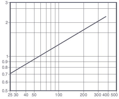
Air-flow characteristic
Function and typical applications
The VB14 admits air to condensing steam or liquid systems when vacuum formation could inhibit drainage or operation. Typical applications include steam inlets to air coils, heat exchangers, sparge systems, jacketed kettles, boiler feedwater tanks, chilled-water lines and liquid process lines.
Size, connections and construction
| System connection | ½ inch |
|---|---|
| Air inlet | ⅛ inch |
| Standard connection in TI-4-103-US | NPT |
| Option | BSP connections |
| Construction | Brass body with stainless steel valve components |
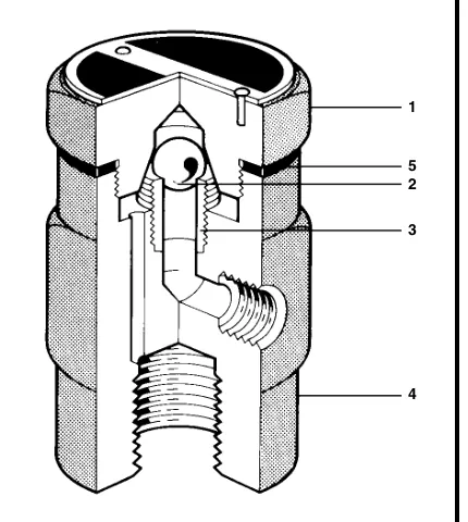
Construction materials
| No. | Part | Material |
|---|---|---|
| 1 | Cap | Brass, CU ZN 39 PB2 |
| 2 | Valve check ball | Stainless steel, Z 100 CD 17 |
| 3 | Valve seat | Stainless steel, Z10 CN 18 08 |
| 4 | Body | Brass, CU ZN 39 PB2 |
| 5 | Gasket | Nickel-reinforced exfoliated graphite |
Operating limits and characteristics
| Maximum operating pressure, PMO | 210 psig (14 bar g) |
|---|---|
| Maximum operating temperature | 500 °F (260 °C) |
| Maximum allowable pressure, PMA | 232 psig from 0 to 500 °F (16 bar g from 0 to 260 °C) |
| Maximum allowable temperature, TMA | 500 °F from 0 to 232 psig (260 °C from 0 to 14 bar g) |
| Maximum Cv | 0.625 |
| Vacuum required to open | 2 in H₂O (0.15 in Hg) |
Local regulations may restrict use below the quoted conditions. The limiting conditions apply to standard connections only.
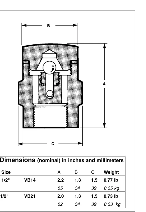
Nominal dimensions and mass
| Size | A | B | C | Mass |
|---|---|---|---|---|
| ½-inch VB14 | 2.2 in / 55 mm | 1.3 in / 34 mm | 1.5 in / 39 mm | 0.77 lb / 0.35 kg |
Specification guidance
Use a vacuum-breaking device on modulating or on/off heat exchangers and coils except where the system is designed for vacuum return. Install it on the supply side between the control valve and the equipment. The VB14 uses a hardened ball-check design with stainless steel working components and a brass body suitable for the stated operating conditions.
Installation
Install vertically with the cap at the top, normally at the highest point of the circuit. Large coils or equipment may require more than one unit. Fit an isolation valve where appropriate to facilitate servicing.
Maintenance note in TI-4-103-US
After isolating the device from system pressure, the cap can be removed to inspect the ball and seat areas for debris. The current installation guide should govern maintenance decisions and identifies the VB14 as a non-maintainable product.
Installation and Maintenance Guide
- Safety information
- Product information
- Installation
- Commissioning
- Operation
- Maintenance
- Spare parts
1. Safety information
Important: Safe operation can only be guaranteed when the product is properly installed, commissioned, used and maintained by qualified personnel in accordance with the operating instructions. Follow the general installation and safety instructions for pipeline and plant construction, and use the correct tools and safety equipment.
1.1 Intended use
Refer to the installation and maintenance instructions, nameplate and technical information to confirm that the VB14 is suitable for the intended application. The product falls within the SEP category for Group 2 gases and Group 2 liquids under the applicable EU and UK pressure-equipment requirements.
| Product | Group 1 gases | Group 2 gases | Group 1 liquids | Group 2 liquids |
|---|---|---|---|---|
| VB14 | — | SEP | — | SEP |
- The product is designed for steam, air or water/condensate in Group 2. Contact Spirax Sarco before considering another fluid.
- Check material suitability and all pressure and temperature limits. Provide a safety device if the product limits are lower than the system limits or a malfunction could cause dangerous overpressure or overtemperature.
- Determine the correct installation position and fluid-flow direction.
- Do not subject the product to external stresses imposed by the connected system. The installer is responsible for assessing and reducing those stresses.
- Remove protective covers from connections and, where applicable, protective film from nameplates before use on steam or other high-temperature duties.
1.2 Access
Provide safe access and, where necessary, a suitably guarded working platform. Arrange appropriate lifting equipment if required.
1.3 Lighting
Provide adequate lighting, particularly where detailed work is required.
1.4 Hazardous liquids or gases
Consider the current and previous contents of the pipeline, including flammable materials, substances hazardous to health and extreme temperatures.
1.5 Hazardous surroundings
Assess explosion-risk areas, oxygen deficiency, dangerous gases, extreme temperatures, hot surfaces, fire hazards, excessive noise and moving machinery.
1.6 The system
Assess how the proposed work affects the complete system and personnel. Isolation must not disable vents, protective devices, controls or alarms. Operate isolation valves gradually to avoid system shock.
1.7 Pressure systems
Isolate all pressure and vent it safely to atmosphere. Consider double isolation and the locking or labelling of closed valves. Do not assume that the system is depressurised merely because a pressure gauge reads zero.
1.8 Temperature
Allow sufficient time after isolation for the temperature to return to a safe level.
1.9 Tools and consumables
Confirm that suitable tools and consumables are available before starting work. Use only genuine replacement products where applicable.
1.10 Protective clothing
Assess the need for protection against chemicals, high or low temperature, radiation, noise, falling objects, and hazards to the eyes and face.
1.11 Permits to work
Work must be carried out or supervised by a competent person. Installation and operating personnel must be trained in correct use. Follow formal permit-to-work systems where present; otherwise ensure that a responsible person understands the work and arrange a safety assistant or warning notices where necessary.
1.12 Handling
Assess manual-handling risks by considering the task, person, load and work environment, and use an appropriate handling method.
1.13 Residual hazards
The external surface can become very hot. At the VB14 maximum allowable condition, surface temperature may approach 260 °C (500 °F). The product is not self-draining, so take care during removal.
1.14 Freezing
Protect the product from frost damage when it may be exposed to temperatures below freezing.
1.15 Disposal
The product is recyclable unless stated otherwise. Check current product-compliance information and follow local recycling and disposal regulations.
1.17 Returning products
When returning a product, provide written information about contamination residues, mechanical damage, hazards and required precautions, including relevant safety data sheets.
2. General product information
2.1 Description
The VB14 is a small, purpose-designed brass vacuum breaker for general applications on condensing vapour, steam or liquid systems at pressures up to 14 bar g (203 psi g).
Standards: The product complies with the relevant EU Pressure Equipment Directive and UK Pressure Equipment (Safety) Regulations.
Certification: A manufacturer’s Typical Test Report is available. State all certification and inspection requirements when placing the order. The installation guide refers to technical information sheet TI-P019-02 for further data.
2.2 Sizes and pipe connections
| Connection | VB14 |
|---|---|
| System connection | ½-inch screwed BSP or NPT |
| Air inlet connection | ⅛-inch screwed BSP or NPT |
2.3 Pressure and temperature limits
| Body design condition | PN16 |
|---|---|
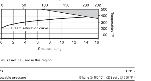
| PMA, maximum allowable pressure | 16 bar g at 180 °C (232 psi g at 356 °F) |
| TMA, maximum allowable temperature | 260 °C at 7 bar g (500 °F at 101 psi g) |
| Minimum allowable temperature | -196 °C (-321 °F) |
| PMO, maximum operating pressure for saturated steam | 14 bar g (203 psi g) |
| TMO, maximum operating temperature | 260 °C at 7 bar g (500 °F at 101 psi g) |
| Minimum operating temperature | 0 °C (32 °F) |
| Maximum cold hydraulic test pressure | 24 bar g (348 psi g) |
3. Installation
Before installation: Observe all safety information in Section 1 and confirm suitability against the instructions, nameplate and technical data.
- Check material, pressure and temperature limits. Fit a safety device if the product’s maximum operating limit is below the system limit.
- Determine the correct installation position and fluid-flow direction.
- Remove all protective covers and any applicable nameplate film before high-temperature service.
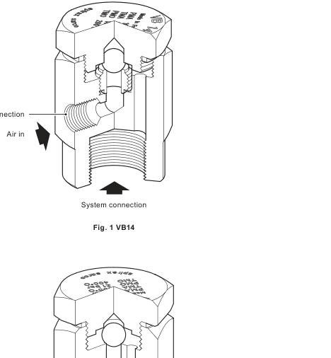
- Always install vertically with the system connection at the bottom.
The air inlet discharges to atmosphere. Lead it to a safe location because discharged fluid may reach 100 °C (212 °F).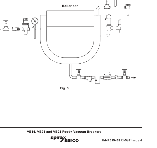
4. Commissioning
After installation or maintenance, confirm that the system is fully functional and test all alarms and protective devices.
5. Operation
The VB14 protects steam plant and process equipment against vacuum while allowing condensate to drain effectively from pipework and storage vessels. The valve has a Kv of 0.52 and requires a differential pressure of 4.6 mmHg to open.
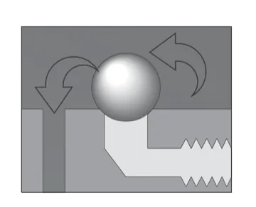
Normal operation
The precision-ground stainless steel ball is held firmly on its seat, providing tight shut-off.
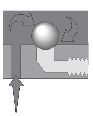
Cooling
Steam begins to condense and the pressure falls. The ball remains on its upper seat until pressure in the upper chamber drops below the air-inlet pressure, which is usually atmospheric.
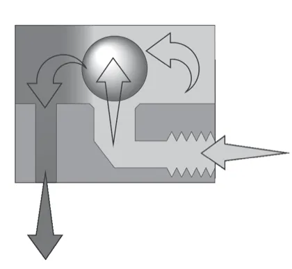
At the point of vacuum
The ball lifts from its seat and air is drawn through the upper chamber, preventing vacuum from forming.
6. Maintenance
Before maintenance: Observe the safety information in Section 1.
The VB14 is a non-maintainable product. Replace the complete unit in the event of failure.
7. Spare parts
No spare parts are available.
Ordering example
1 off Spirax Sarco VB14 vacuum breaker with ½-inch screwed BSP connections.