
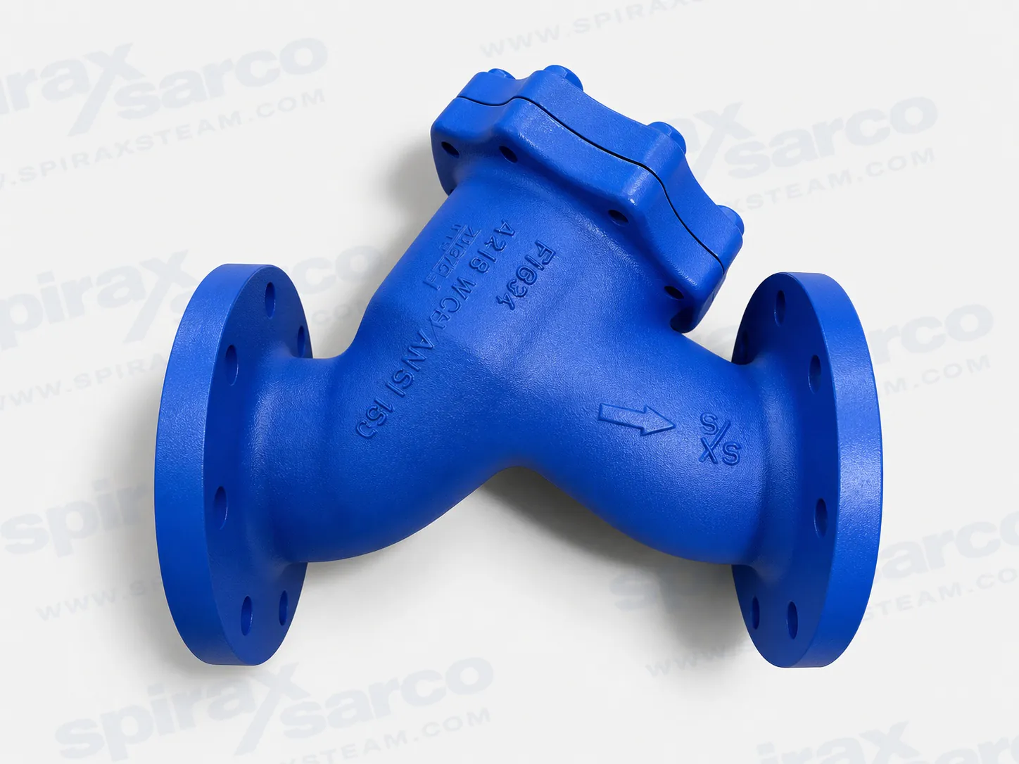
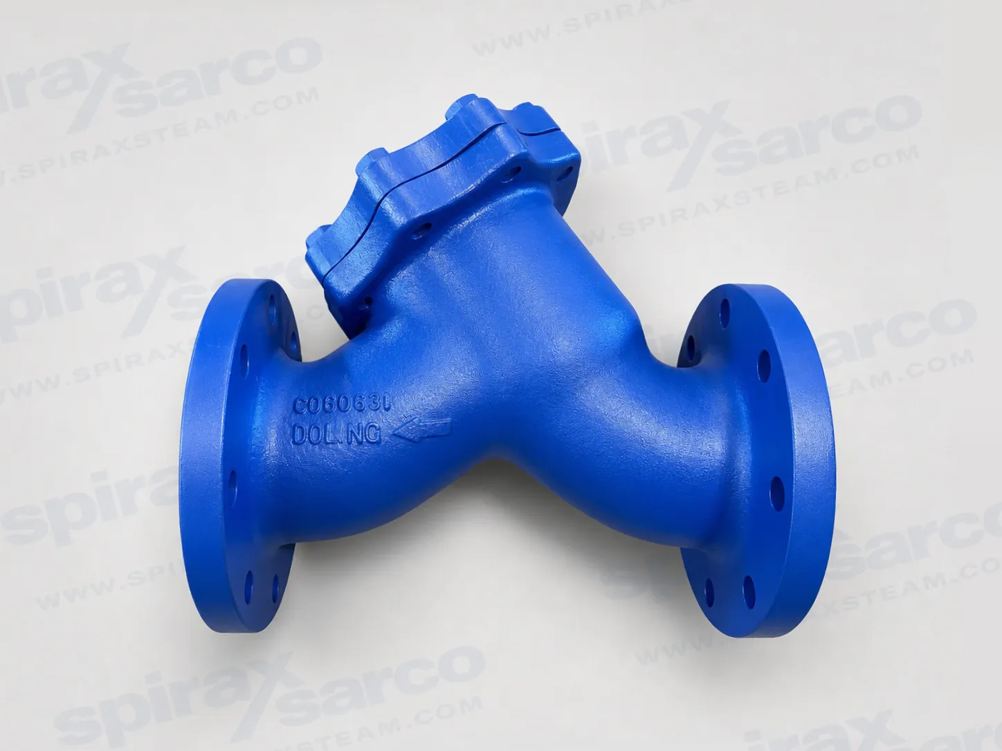
FIG34
Fig 34 Carbon Steel Y-type Strainer
Integrally flanged carbon steel Y-type strainer for DN15 to DN400 pipelines, with EN, ASME and JIS/KS flange options and selectable stainless-steel or Monel screens.
Fig 34 carbon steel Y-type strainer
The Spirax Sarco Fig 34 is an integrally flanged carbon steel Y-type strainer designed to remove rust, scale and other debris from pipelines. Its documented range spans DN15 to DN400, with EN, ASME and JIS/KS flange options selected according to size, material standard and required pressure class.
The screen specification scales with the line size: the standard stainless-steel screen uses 0.8 mm perforations from DN15 to DN80, 1.6 mm perforations from DN100 to DN200 and 3 mm perforations from DN250 to DN400. Alternative perforations, mesh sizes and Monel screens are available for applications that need a different balance between debris retention and pressure drop.
Range and selection
- DN15-DN200, EN material: EN 1092 PN40 flanges.
- DN15-DN200, ASTM material: ASME Class 150, ASME Class 300 and JIS/KS 20 flanges.
- DN250-DN400: EN 1092 PN16, PN25 or PN40; ASME B16.5 Class 150 or 300; and JIS/KS 10 or 20.
- Service envelope: pressure and temperature limits depend on flange and material configuration; use the applicable tables and curves below rather than a single headline rating.
For installation, align the body arrow with the flow direction. In steam or gas service the strainer pocket should lie in the horizontal plane; in liquid service it should point downwards. The screen and cap or cover gasket are available as service parts.
EN material, DN15 to DN200
Technical Information: TI-P064-01, CMGT Issue 14.
The Fig 34 is a carbon steel integrally flanged Y-type strainer in EN material. It complies with the European Pressure Equipment Directive 2014/68/EU. A manufacturer's Typical Test Report is standard; EN 10204 3.1 certification for body and cap is available by order.
Sizes, screens and connections
Sizes: DN15, DN20, DN25, DN32, DN40, DN50, DN65, DN80, DN100, DN125, DN150 and DN200. Standard flange: EN 1092 PN40.
| Screen | Specification | Size range |
|---|---|---|
| Standard stainless steel | 0.8 mm perforations | DN15-DN80 |
| Standard stainless steel | 1.6 mm perforations | DN100-DN200 |
| Optional stainless steel | 1.6 mm or 3.0 mm; mesh 40, 100 or 200 | As specified |
| Optional Monel | 0.8 mm, 1.6 mm or 3.0 mm; mesh 100 | As specified |
| Strainer size | Blowdown valve | Drain valve |
|---|---|---|
| DN15 | ¼ in | ¼ in |
| DN20-DN25 | ½ in | ½ in |
| DN32-DN40 | 1 in | ¾ in |
| DN50-DN125 | 1¼ in | ¾ in |
| DN150-DN200 | 2 in | ¾ in |
Pressure and temperature limits
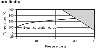
| Body design condition | PN40 |
|---|---|
| PMA | 40 bar g at 50 °C |
| TMA | 400 °C at 23.8 bar g |
| Minimum allowable temperature | -29 °C |
| PMO | 40 bar g at 50 °C |
| TMO | 400 °C at 23.8 bar g |
| Vacuum service | Safe under full vacuum conditions |
| Cold hydraulic test pressure | 69 bar g |
Materials
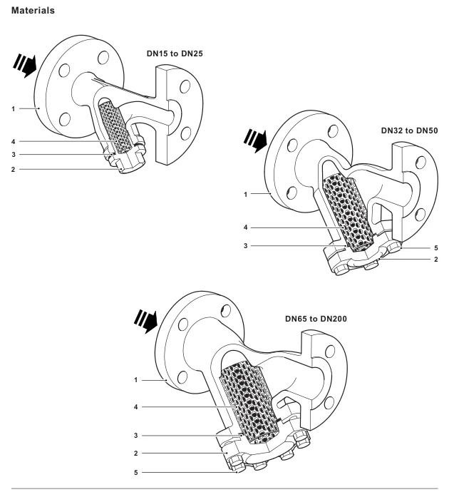
| No. | Part | Material |
|---|---|---|
| 1 | Body | Carbon steel 1.0619 |
| 2 | Cap, DN15-DN50 | Forged steel C22.8 |
| 2 | Cap, DN65-DN200 | Carbon steel 1.0619 |
| 3 | Cap gasket | Reinforced exfoliated graphite |
| 4 | Strainer screen | Stainless steel ASTM A240 316L |
| 5 | Bolts | Stainless steel ASTM A193 B7 |
Flow coefficients
| Screen | DN15 | DN20 | DN25 | DN32 | DN40 | DN50 | DN65 | DN80 | DN100 | DN125 | DN150 | DN200 |
|---|---|---|---|---|---|---|---|---|---|---|---|---|
| Perforations 0.8/1.6/3.0 mm | 5 | 8 | 13 | 22 | 29 | 46 | 72 | 103 | 155 | 237 | 340 | 588 |
| Mesh 40/100 | 5 | 8 | 13 | 22 | 29 | 46 | 72 | 103 | 155 | 237 | 340 | 588 |
| Mesh 200 | 4 | 6 | 10 | 17 | 23 | 37 | 58 | 83 | 124 | 186 | 268 | 464 |
Cv (UK) = Kv × 0.963; Cv (US) = Kv × 1.156.
Dimensions and weights
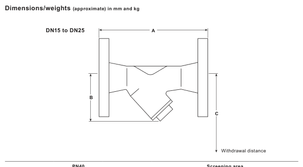
| Size | A mm | B mm | C mm | Screening area cm² | Weight kg |
|---|---|---|---|---|---|
| DN15 | 130 | 70 | 110 | 27 | 2.1 |
| DN20 | 150 | 80 | 130 | 43 | 2.9 |
| DN25 | 160 | 95 | 150 | 73 | 3.8 |
| DN32 | 180 | 130 | 235 | 135 | 6.5 |
| DN40 | 200 | 146 | 260 | 164 | 9.0 |
| DN50 | 230 | 180 | 320 | 251 | 10.5 |
| DN65 | 290 | 200 | 325 | 327 | 17.5 |
| DN80 | 310 | 205 | 330 | 361 | 24.0 |
| DN100 | 351 | 255 | 405 | 545 | 30.0 |
| DN125 | 400 | 315 | 510 | 843 | 49.0 |
| DN150 | 480 | 345 | 560 | 1117 | 68.0 |
| DN200 | 600 | 440 | 710 | 1909 | 128.0 |
Installation, ordering and service parts
Install in the body-arrow flow direction. For steam or gases, keep the pocket in the horizontal plane; for liquids, point it downwards. For full procedures see Installation and Maintenance Instructions IM-S60-18. The product is recyclable when disposed of with due care.
Available spares are the strainer screen and a packet of three cap gaskets. State the strainer size, screen material and required perforation or mesh when ordering.
Recommended tightening torques
| Size | Quantity | Fastener | Torque N m |
|---|---|---|---|
| DN15 | 1 | 22 mm / M28 | 50-55 |
| DN20 | 1 | 27 mm / M32 | 60-66 |
| DN25 | 1 | 27 mm / M42 | 100-110 |
| DN32-DN40 | 4 | 19 mm / M12 × 30 | 20-24 |
| DN50 | 6 | 19 mm / M12 × 35 | 20-24 |
| DN65 | 8 | 19 mm / M12 × 35 | 20-24 |
| DN80 | 8 | 19 mm / M12 × 35 | 30-35 |
| DN100 | 8 | 24 mm / M16 × 45 | 50-55 |
| DN125 | 8 | 30 mm / M20 × 50 | 70-77 |
| DN150 | 8 | 30 mm / M20 × 55 | 80-88 |
| DN200 | 12 | 36 mm / M24 × 65 | 120-130 |
ASTM material, DN15 to DN200
Technical Information: TI-P064-02, CMGT Issue 15.
This integrally flanged carbon steel Y-type strainer is offered in ASTM material and removes rust, scale and other pipeline debris. It complies with the European Pressure Equipment Directive 2014/68/EU. A manufacturer's Typical Test Report is standard; EN 10204 3.1 certification for body and cap is available by order.
Sizes, screens and connections
Sizes: DN15-DN200 (½-8 in). Standard flanges: ASME Class 150, ASME Class 300 and JIS/KS 20.
| Screen | Specification | Size range |
|---|---|---|
| Standard stainless steel | 0.8 mm perforations | DN15-DN80 |
| Standard stainless steel | 1.6 mm perforations | DN100-DN200 |
| Optional stainless steel | 1.6 mm or 3.0 mm; mesh 40, 100 or 200 | As specified |
| Optional Monel | 0.8 mm, 1.6 mm or 3.0 mm; mesh 100 | As specified |
| Strainer size | Blowdown valve | Drain valve |
|---|---|---|
| DN15 | ¼ in | ¼ in |
| DN20-DN25 | ½ in | ½ in |
| DN32-DN40 | 1 in | 1 in |
| DN50-DN125 | 1¼ in | 1¼ in |
| DN150-DN200 | 2 in | ¾ in |
Pressure and temperature limits
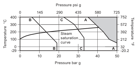
| Body design condition | PN50 / ASME 300 |
|---|---|
| PMA | 50 bar g at 37.7 °C (725 psi g at 100 °F) |
| TMA | 398.8 °C at 34.8 bar g (750 °F at 505 psi g) |
| Minimum allowable temperature | -29 °C (-20.2 °F) |
| PMO | 50 bar g at 37.7 °C |
| TMO | 398.8 °C at 34.8 bar g |
| Vacuum service | Safe under full vacuum conditions |
| Cold hydraulic test pressure | 78 bar g (1131 psi g) |
Materials
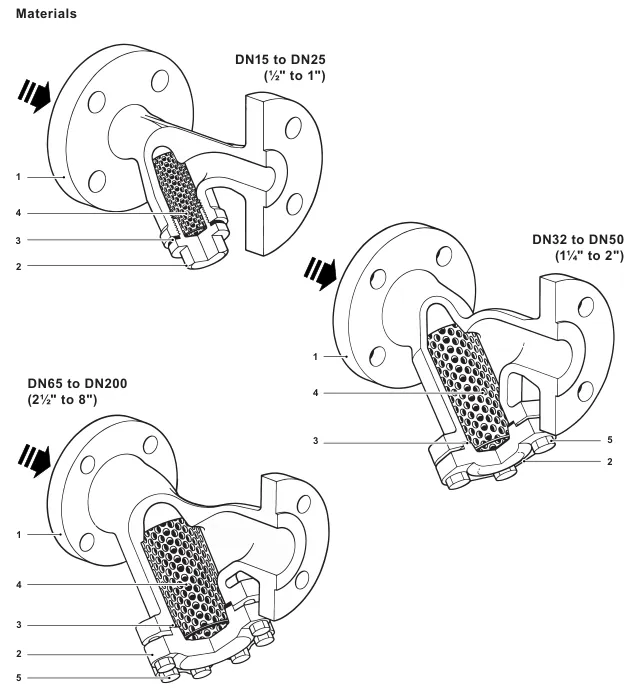
| No. | Part | Material |
|---|---|---|
| 1 | Body | Carbon steel ASTM A216 WCB |
| 2 | Cap, DN15-DN50 | Forged steel A105N |
| 2 | Cap, DN65-DN200 | Carbon steel ASTM A216 WCB |
| 3 | Cap gasket | Reinforced exfoliated graphite |
| 4 | Strainer screen | Stainless steel ASTM A240 316L |
| 5 | Bolts | Carbon steel ASTM A193 B7 |
Flow coefficients
| Screen | DN15 | DN20 | DN25 | DN32 | DN40 | DN50 | DN65 | DN80 | DN100 | DN125 | DN150 | DN200 |
|---|---|---|---|---|---|---|---|---|---|---|---|---|
| Perforations 0.8/1.6/3.0 mm | 5 | 8 | 13 | 22 | 29 | 46 | 72 | 103 | 155 | 237 | 340 | 588 |
| Mesh 40/100 | 5 | 8 | 13 | 22 | 29 | 46 | 72 | 103 | 155 | 237 | 340 | 588 |
| Mesh 200 | 4 | 6 | 10 | 17 | 23 | 37 | 58 | 83 | 124 | 186 | 268 | 464 |
Dimensions and weights
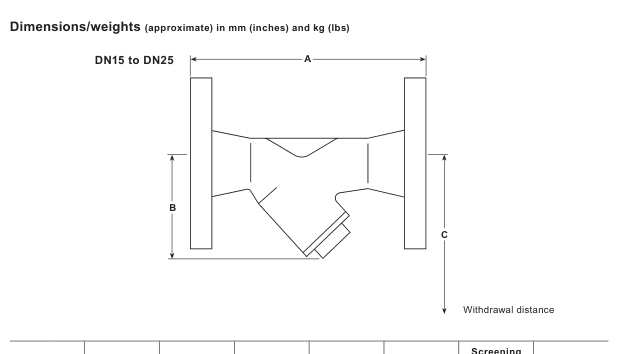
| Size | ASME 150 A mm | ASME 300 A mm | JIS/KS 20 A mm | B mm | C mm | Area cm² | kg |
|---|---|---|---|---|---|---|---|
| DN15 | 120 | 127 | 126 | 70 | 110 | 27 | 2.1 |
| DN20 | 144 | 150 | 150 | 80 | 130 | 43 | 2.9 |
| DN25 | 154 | 160 | 159 | 95 | 150 | 73 | 3.8 |
| DN32 | 180 | 180 | 178 | 130 | 235 | 135 | 6.5 |
| DN40 | 200 | 208 | 202 | 146 | 260 | 164 | 9.0 |
| DN50 | 230 | 240 | 232 | 180 | 320 | 251 | 10.5 |
| DN65 | 290 | 289 | 278 | 200 | 325 | 327 | 17.5 |
| DN80 | 310 | 311 | 297 | 205 | 330 | 361 | 24.0 |
| DN100 | 351 | 351 | 333 | 255 | 405 | 545 | 30.0 |
| DN125 | 401 | 401 | 383 | 315 | 510 | 843 | 49.0 |
| DN150 | 473 | 478 | 461 | 345 | 560 | 1117 | 68.0 |
| DN200 | 593 | 600 | 577 | 440 | 710 | 1909 | 128.0 |
Installation, warning and service parts
Install in the body-arrow flow direction. Keep the pocket horizontal for steam or gas and point it downwards for liquids. For full procedures see Installation and Maintenance Instructions IM-S60-18. The cap gasket contains a thin stainless-steel support ring that can cause injury if handled or disposed of carelessly.
Available spares are the strainer screen and a packet of three cap gaskets. State size, screen material, perforation or mesh, and flange connection when ordering.
Recommended tightening torques
| Size | Quantity | Fastener | Torque N m |
|---|---|---|---|
| DN15 | 1 | 22 mm | 50-55 |
| DN20 | 1 | 27 mm | 60-66 |
| DN25 | 1 | 27 mm | 100-110 |
| DN32-DN40 | 4 | 19 mm / M12 × 30 | 20-24 |
| DN50 | 6 | 19 mm / M12 × 35 | 20-24 |
| DN65 | 8 | 19 mm / M12 × 35 | 20-24 |
| DN80 | 8 | 19 mm / M12 × 35 | 30-35 |
| DN100 | 8 | 24 mm / M16 × 45 | 50-55 |
| DN125 | 8 | 30 mm / M20 × 50 | 70-77 |
| DN150 | 8 | 30 mm / M20 × 55 | 80-88 |
| DN200 | 12 | 36 mm / M24 × 65 | 120-230 |
Large-bore range, DN250 to DN400
Technical Information: TI-P168-07, CMGT Issue 6.
This integrally flanged Fig 34 removes rust, scale and other debris from large-bore pipelines. It complies with the European Pressure Equipment Directive 2014/68/EU and carries the CE mark when required. EN 10204 3.1 material certification for body and cover is available.
Sizes, screens, connections and Kv
Sizes: DN250, DN300, DN350 and DN400. Standard raised-face connections are EN 1092 PN16, PN25 or PN40; ASME B16.5 Class 150 or Class 300; and JIS/KS 10 or 20.
| Screen | Specification |
|---|---|
| Standard stainless steel | 3 mm perforations |
| Optional perforations | 0.8 mm, 1.6 mm or 5 mm |
| Optional mesh | 40, 100 or 200 |
| Optional Monel | Available on request |
| Screen | DN250 | DN300 | DN350 | DN400 |
|---|---|---|---|---|
| Perforated Kv | 950 | 1300 | 1800 | 2300 |
| Mesh Kv | 850 | 1100 | 1500 | 1900 |
The cover can be drilled for a 2 in blowdown valve and a 2 in drain valve.
Materials
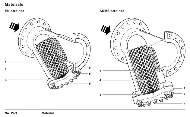
| No. | Part | Material |
|---|---|---|
| 1 | Body | Carbon steel EN 10213 1.0619+N / ASTM A216 WCB |
| 2 | Cover | Carbon steel EN 10213 1.0619+N / ASTM A216 WCB or ASTM A105N |
| 3 | Gasket | Reinforced exfoliated graphite |
| 4 | Screen | Stainless steel |
| 5 | Stud | Carbon steel ASTM A193 B7 |
| 6 | Nut | Carbon steel ASTM A194 2H |
EN pressure and temperature limits
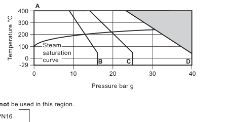
| Rating | PMA | TMA | PMO saturated steam | TMO |
|---|---|---|---|---|
| PN40 | 40 bar g at 50 °C | 400 °C at 23.8 bar g | 30.7 bar g at 237 °C | 400 °C at 23.8 bar g |
| PN25 | 25 bar g at 50 °C | 400 °C at 14.8 bar g | 20 bar g at 215 °C | 400 °C at 14.8 bar g |
| PN16 | 16 bar g at 50 °C | 400 °C at 9.5 bar g | 13.2 bar g at 196 °C | 400 °C at 9.5 bar g |
ASME pressure and temperature limits
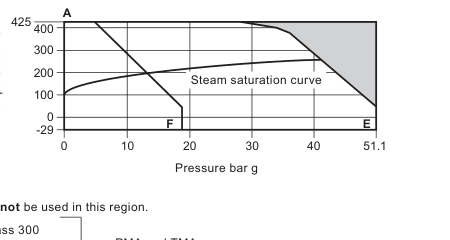
| Rating | PMA | TMA | PMO saturated steam | TMO |
|---|---|---|---|---|
| Class 300 | 51.1 bar g at 38 °C | 425 °C at 28.8 bar g | 41.5 bar g at 254 °C | 425 °C at 28.8 bar g |
| Class 150 | 19.6 bar g at 38 °C | 425 °C at 5.5 bar g | 13.6 bar g at 197 °C | 425 °C at 5.5 bar g |
JIS/KS pressure and temperature limits
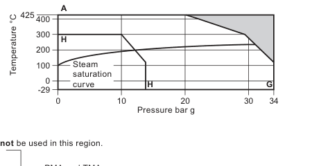
| Rating | PMA | TMA | PMO saturated steam | TMO |
|---|---|---|---|---|
| JIS/KS 20 | 34 bar g at 120 °C | 425 °C at 20.0 bar g | 30.1 bar g at 236 °C | 425 °C at 20.0 bar g |
| JIS/KS 10 | 14 bar g at 120 °C | 300 °C at 10.0 bar g | 12.4 bar g at 193 °C | 300 °C at 10.0 bar g |
Minimum allowable and operating temperature: -29 °C. The product is safe under full vacuum conditions. Maximum cold hydraulic test pressure is 1.5 × PMA.
Dimensions and weights
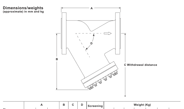
| Size | EN/JIS A mm | ASME 150 A mm | ASME 300 A mm | B EN/ASME mm | C EN/ASME mm | Screen area mm² EN/ASME | Weight range kg |
|---|---|---|---|---|---|---|---|
| DN250 | 730 | 622 | 622 | 515 / 560 | 957 / 1005 | 371800 / 371800 | 163-218 |
| DN300 | 850 | 699 | 711 | 570 / 640 | 1020 / 1098 | 439300 / 439300 | 214-344 |
| DN350 | 980 | 787 | 838 | 620 / 770 | 1205 / 1320 | 653400 / 593800 | 377-454 |
| DN400 | 1100 | 914 | 864 | 710 / 730 | 1340 / 1360 | 641400 / 641400 | 487-617 |
Installation, warning and service parts
Install in the body-arrow flow direction. Keep the pocket horizontal for steam or gas and point it downwards for liquids. For full procedures see Installation and Maintenance Instructions IM-S60-18. The cover gasket contains a thin stainless-steel support ring that can cause injury if mishandled.
Available spares are the strainer screen and a packet of three cover gaskets. State size, flange connection, screen material and required perforation or mesh when ordering.
Recommended cover tightening torques
| Size | Connection | Quantity | Fastener | Torque N m |
|---|---|---|---|---|
| DN250 | ASME Class 150 / EN | 16 | 1¼ in / ¾ in-10UNC | 160-180 |
| DN250 | ASME Class 300 | 16 | 1 7/16 in / 7/8 in-9UNC | 180-200 |
| DN300 | ASME Class 150 / EN | 16 | 1¼ in / ¾ in-10UNC | 200-220 |
| DN300 | ASME Class 300 | 18 | 1 7/16 in / 7/8 in-9UNC | 210-230 |
| DN350 | ASME Class 150 / EN | 20 | 1¼ in / ¾ in-10UNC | 220-240 |
| DN350 | ASME Class 300 | 22 | 1 7/16 in / 7/8 in-9UNC | 230-250 |
| DN400 | ASME Class 150 / EN | 22 | 1 7/16 in / 7/8 in-9UNC | 330-350 |
| DN400 | ASME Class 300 | 16 | 1 13/16 in / 1⅛ in-7UNC | 480-530 |