
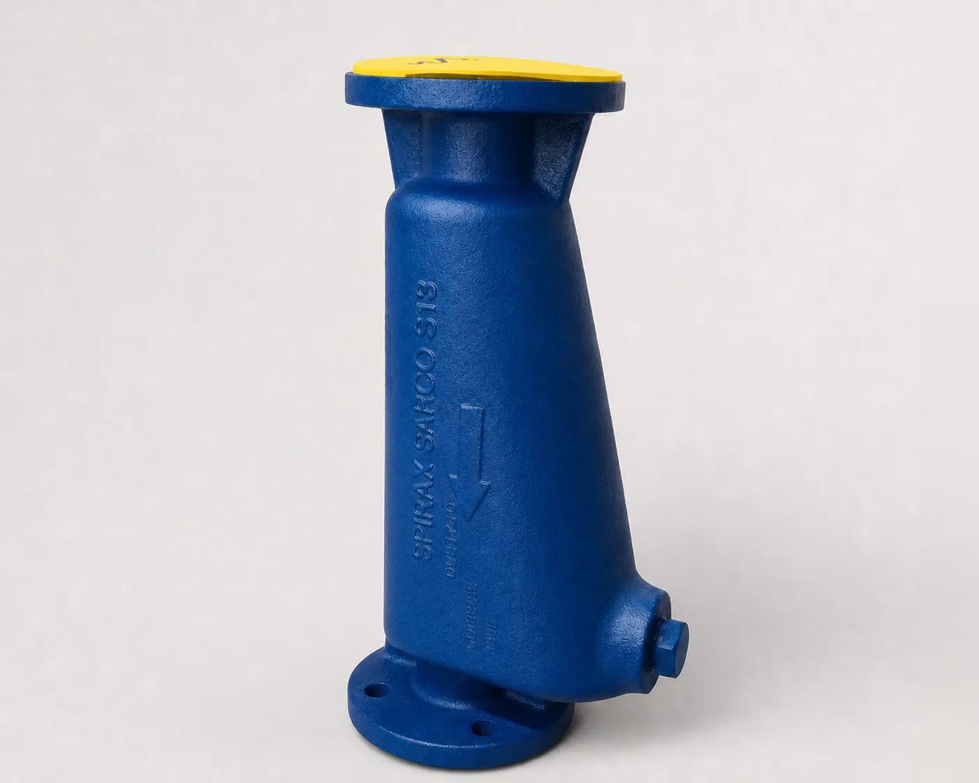
The Spirax Sarco S13 is a flanged SG iron baffle-type steam separator for removing entrained liquid from steam, compressed-air and gas systems. Covering DN40 to DN200 with multiple flange standards, it combines a dedicated drain connection with an accessible inspection plug for dependable moisture removal. Compare the wider Spirax Sarco steam separator range when selecting materials, pressure ratings or connection types for other duties.
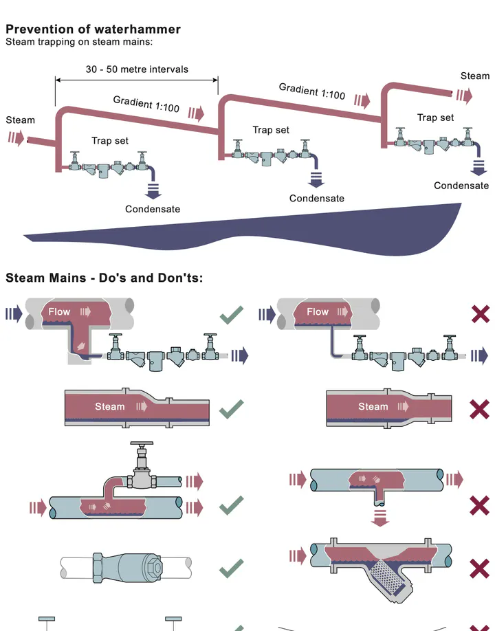
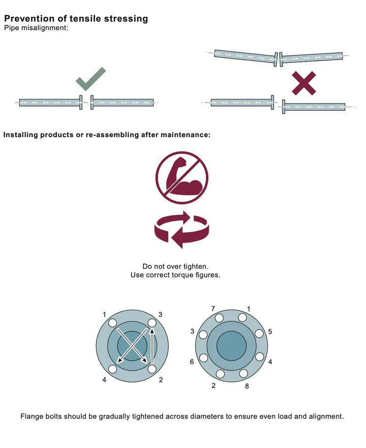
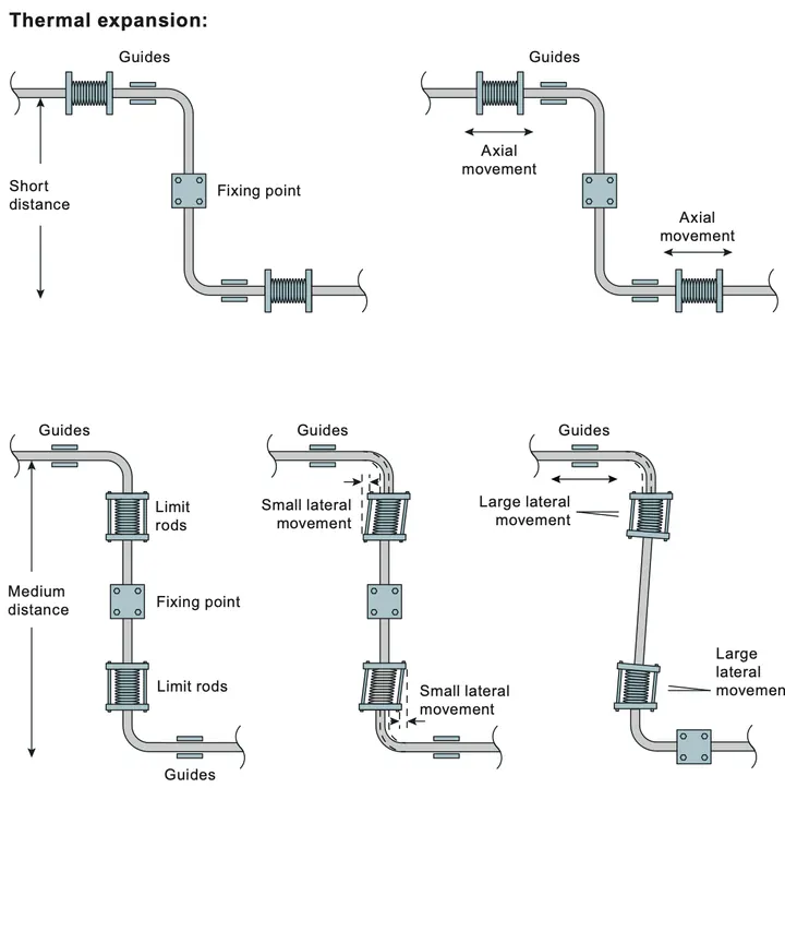
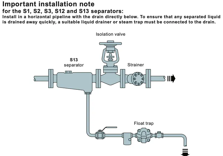
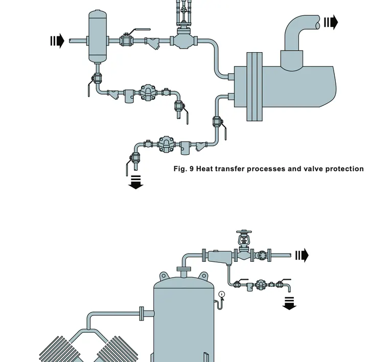
For effective drainage, install the S13 horizontally with the drain directly below and follow the appropriate steam-trap selection route for the drain set. Suitable pipeline strainers and filters can help protect downstream drainage equipment where solid contamination is present, while drier steam supports more predictable operation across the pressure-reducing valve range and other process equipment. The S13 separator is an SG iron baffle-type separator used for the removal of entrained liquids in steam, compressed-air or gas systems. Fitting insulation jackets increases separator performance. This product fully complies with the requirements of the EU Pressure Equipment Directive and the UK Pressure Equipment (Safety) Regulations, and is designed in accordance with ASME B31.3. This product is available with a manufacturer's Typical Test Report. All certification and inspection requirements must be stated when the order is placed. Important: An S13 may be supplied with a lower pressure rating than that cast into the body. Use the operating chart for the actual product limitation. For full details, see Installation and Maintenance Instructions IM-P023-55 supplied with the product. Installation: Install the separator in a horizontal pipeline with the drain directly below. Connect a suitable liquid drainer or steam trap to drain connection E so separated liquid is removed quickly. Disposal: The product is recyclable. No ecological hazard is anticipated when it is disposed of with due care. Ordering example: One DN50 Spirax Sarco S13 separator with SG iron body and flanged EN 1092 PN16 connections. Installation and Maintenance Instructions for Spirax Sarco baffle-type separators. Safe operation can only be guaranteed when these products are correctly installed, commissioned, used and maintained by qualified personnel in accordance with the operating instructions. General safety instructions for pipeline and plant construction, and the correct use of tools and safety equipment, must also be followed. Check the Installation and Maintenance Instructions, nameplate and Technical Information Sheet to confirm that the product is suitable for the intended application. The products are designed for steam and compressed air in Group 2 of the Pressure Equipment Directive. Provide safe access, a guarded working platform where necessary, and suitable lifting gear. Provide adequate lighting, especially for detailed work. Consider flammable or hazardous substances and temperature extremes in the pipeline. Consider explosion risk, oxygen deficiency, dangerous gases, hot surfaces, fire, noise and moving machinery. Assess the effect of isolation and other work on the complete system, controls, alarms and protective devices. Isolate and safely vent pressure. Consider double isolation and lock or label closed valves. A zero gauge reading does not prove depressurisation. Allow temperature to normalise after isolation to prevent burns. Use suitable tools and consumables and only genuine Spirax Sarco replacement parts. Use protection appropriate to chemical, temperature, radiation, noise, falling-object, eye and face hazards. Competent personnel must carry out or supervise work. Follow the permit-to-work system and post warning notices where required. Assess lifting and handling risks for large or heavy products and use an appropriate method. External surfaces may reach 300 °C (572 °F). Many products are not self-draining; take care when removing or dismantling them. Protect non-self-draining products against frost damage. The products are recyclable when handled with due care. Check local rules and current Spirax Sarco product-compliance information. Provide written information and safety data sheets for contamination or damage that may create health, safety or environmental risks. Cast iron is brittle. If a cast-iron product is dropped and may be damaged, do not use it unless the manufacturer has inspected and pressure-tested it. Follow good steam-engineering practice to prevent waterhammer and tensile stress. All products covered by this guide are baffle-type separators used to remove entrained liquids from steam, compressed-air and gas systems. Insulation jackets are recommended to improve performance. S7 and S8 separators are designed and manufactured in accordance with EN 13445:2002, Unfired Pressure Vessels. Before installation, follow Section 1. Check body markings, nameplate and Technical Information Sheet. Verify materials and pressure and temperature limits; establish the correct position and flow direction; remove protective covers and nameplate film; and apply insulation where required. Install horizontally with the drain below and connect a suitable liquid drainer or float-type steam trap. If air may collect, connect a suitable air vent; otherwise replace the plastic transit plug with a carbon-steel Class 3000 lb plug. Install horizontally with the drain below. Use the support brackets to minimise piping loads. Connect a suitable liquid drainer or steam trap, preferably a float type. Fit an air vent where air can collect, or install the specified carbon-steel plug. After installation or maintenance, confirm that the system is fully functional and test all alarms and protective devices. Separators gather small droplets of entrained liquid and separate them from the gas or vapour flow. The heavier droplets strike the internal baffles, move to the drain connection and leave the system through a steam trap, or through a liquid drainer in air and gas systems. Before maintenance, follow Section 1. S1, S2, S3, S12 and S13 contain no internal components that require routine maintenance. There are no spare parts required or available for these components.Description
Standards
Certification
Sizes and pipe connections
Materials
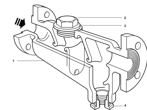
No. Part Material Specification 1 Body SG iron BS EN 1563 / EN-JS1030 / A395 2 Plug Carbon steel 1.0460 (C22.8) / A105N 3 Gasket Reinforced exfoliated graphite — 4 Drain reducing bush Forged carbon steel ASTM A105 Pressure and temperature limits
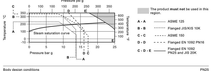
Condition Connection rating Limit PMA — maximum allowable pressure JIS/KS 10K 14 bar g at 120 °C (203 psi g at 248 °F) PN16 16 bar g at 120 °C (232 psi g at 248 °F) PN25 and JIS/KS 20K 25 bar g at 120 °C (363 psi g at 248 °F) ASME 125 13.8 bar g at 65 °C (200 psi g at 149 °F) ASME 150 17.2 bar g at 38 °C (250 psi g at 100 °F) TMA — maximum allowable temperature JIS/KS 10K 300 °C at 10 bar g (572 °F at 145 psi g) PN16 350 °C at 11.2 bar g (662 °F at 162 psi g) PN25 and JIS/KS 20K 350 °C at 17.5 bar g (662 °F at 254 psi g) ASME 125 232 °C at 8.6 bar g (450 °F at 125 psi g) ASME 150 343 °C at 8.6 bar g (650 °F at 125 psi g) Minimum allowable temperature All ratings −10 °C (14 °F) PMO — maximum operating pressure for saturated steam JIS/KS 10K 12.3 bar g (178 psi g) PN16 13.7 bar g (198 psi g) PN25 and JIS/KS 20K 21.3 bar g (309 psi g) ASME 125 10.1 bar g (146 psi g) ASME 150 13.9 bar g (202 psi g) TMO — maximum operating temperature JIS/KS 10K 300 °C at 10 bar g (572 °F at 145 psi g) PN16 350 °C at 11.2 bar g (662 °F at 162 psi g) PN25 and JIS/KS 20K 350 °C at 17.5 bar g (662 °F at 254 psi g) ASME 125 232 °C at 8.6 bar g (450 °F at 125 psi g) ASME 150 343 °C at 8.6 bar g (650 °F at 125 psi g) Minimum operating temperature All ratings −10 °C (14 °F). Consult Spirax Sarco for lower temperatures. Maximum cold hydraulic test pressure JIS/KS 10K 20.4 bar g (296 psi g) PN16 24.0 bar g (348 psi g) PN25 and JIS/KS 20K 37.5 bar g (544 psi g) ASME 125 20.7 bar g (300 psi g) ASME 150 25.8 bar g (374 psi g) Dimensions, weight and volume
Metric dimensions
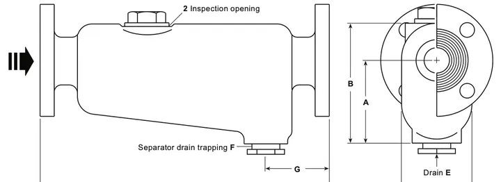
Size A mm B mm C mm D mm E mm F mm G mm Weight kg Volume L DN40 / 1½ 111 156 89 365 12.7 25.4 94 14 1.6 DN50 / 2 146 205 117 456 12.7 25.4 98 25 3.2 DN65 / 2½ 178 249 146 406 19.0 38.1 98 28 4.6 DN80 / 3 178 252 152 483 19.0 38.1 98 36 6.5 DN100 / 4 223 315 197 692 25.4 38.1 118 60 13.5 DN125 / 5 226 397 381 706 25.4 38.1 121 128 38.5 DN150 / 6 226 397 381 706 25.4 38.1 121 130 42.5 DN200 / 8 308 502 426 762 38.1 38.1 140 190 68.0 Imperial dimensions
Size A in B in C in D in E F G in Weight lb Volume gal DN40 / 1½ 4.37 6.14 3.50 14.4 ½ 1 3.70 30.9 0.42 DN50 / 2 5.75 8.07 4.61 18.0 ½ 1 3.86 55.1 0.84 DN65 / 2½ 7.00 9.80 5.75 16.0 ¾ 1½ 3.86 61.7 1.21 DN80 / 3 7.00 9.92 5.98 19.0 ¾ 1½ 3.86 79.4 1.72 DN100 / 4 8.78 12.4 7.76 27.2 1 1½ 4.64 132.3 3.57 DN125 / 5 8.90 15.6 15.0 27.8 1 1½ 4.76 282.2 10.2 DN150 / 6 8.90 15.6 15.0 27.8 1 1½ 4.76 286.6 11.2 DN200 / 8 12.1 19.8 16.8 30.0 1½ 1½ 5.51 418.9 18.0 Recommended tightening torques
Inspection plug item Sizes Spanner Thread Torque 2 DN40–DN65 46 A/F M56 150–165 N m (110–121 lbf ft) 2 DN80–DN200 60 A/F M72 190–210 N m (140–155 lbf ft) Safety, installation and maintenance
1. Safety information
1.1 Intended use
Product Pressure rating Size range Group 2 gases Group 2 liquids S1 16 bar g DN15–DN20 / DN25 / DN32–DN40 SEP / 1 / SEP SEP S2 16 bar g DN32–DN40 / DN50 SEP / 1 SEP S3 16 bar g DN40 / DN50–DN80 / DN100–DN150 / DN200 SEP / 1 / 2 / 1 SEP S5 and S6 50 bar g DN15 / DN20–DN25 / DN32–DN50 SEP / 1 / 2 SEP S7 and S8 14, 20, 23 or 25 bar g DN65–DN350, category varies with rating and size SEP–4 SEP S12 25 bar g DN32–DN40 / DN50 SEP / 1 SEP S13 25 bar g DN40 / DN50–DN80 / DN100–DN125 / DN150–DN200 SEP / 1 / 2 / 2 SEP 1.2 Access
1.3 Lighting
1.4 Pipeline contents
1.5 Surrounding hazards
1.6 The system
1.7 Pressure systems
1.8 Temperature
1.9 Tools
1.10 Protective clothing
1.11 Permits to work
1.12 Handling
1.13 Residual hazards
1.14 Freezing
1.15 Disposal
1.16 Returning products
1.17 Working safely with cast-iron products on steam
2. General product information
Type Material Pressure rating Sizes Connections TI reference S1 SG iron PN16 ½, ¾ and 1 in Screwed TI-P023-02 S2 Cast iron PN16 1¼, 1½ and 2 in Screwed TI-P023-07 S3 Cast iron PN16 DN40–DN200 Flanged TI-P023-24 S5 Carbon steel PN50 / ASME 300 DN15–DN50 Screwed and flanged TI-P023-11 S6 316L austenitic stainless steel PN50 / ASME 300 DN15–DN50 Screwed and flanged TI-P023-12 S7 Carbon steel PN16 and PN40 DN65–DN350 Flanged TI-P138-03 S8 Austenitic stainless steel PN16 and PN40 DN65–DN350 Flanged TI-P138-10 S12 SG iron PN25 1¼, 1½ and 2 in Screwed TI-P023-25 S13 SG iron PN25 DN40–DN200 Flanged TI-P023-26 3. Installation
3.5 S5 and S6
3.6 S7 and S8
4. Commissioning
5. Operation
6. Maintenance
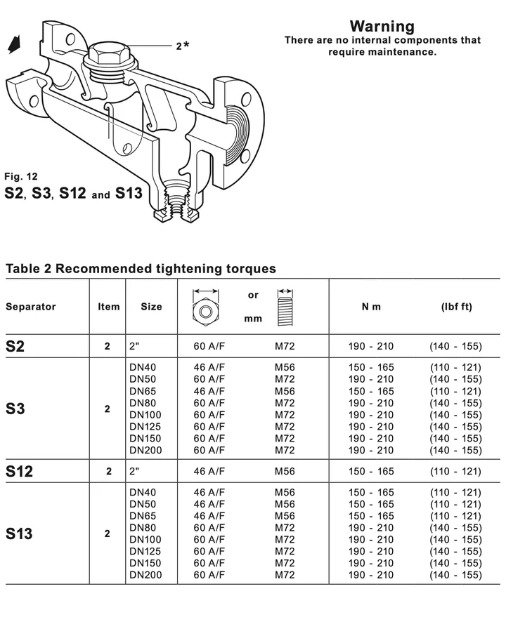
Separator Item Sizes Spanner Thread Torque S13 2 DN40–DN65 46 A/F M56 150–165 N m (110–121 lbf ft) S13 2 DN80–DN200 60 A/F M72 190–210 N m (140–155 lbf ft) 7. Spare parts