
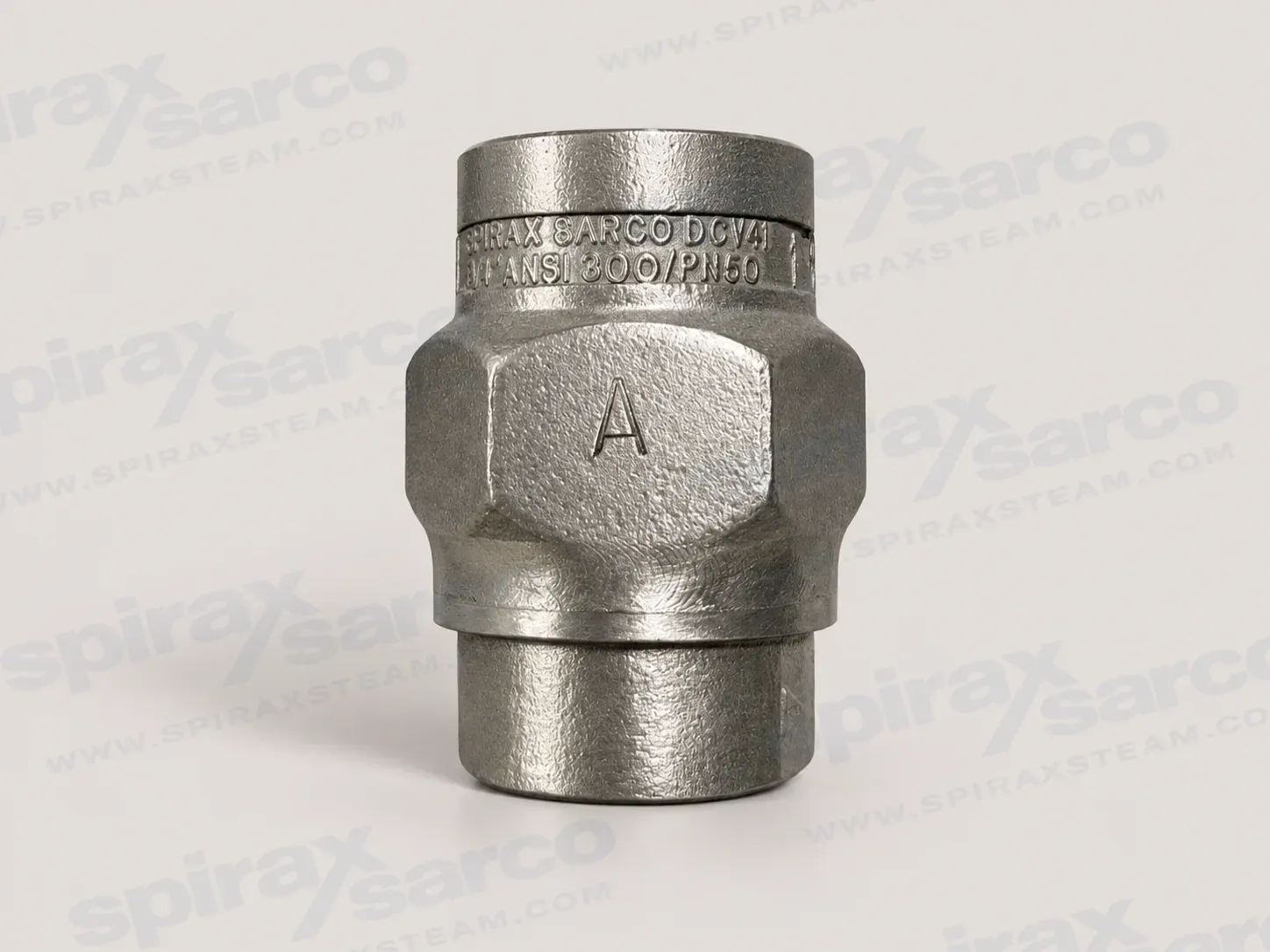
DCV41
DCV41 Austenitic Stainless Steel Disc Check Valve
DCV41 is an austenitic stainless steel disc check valve for preventing reverse flow in process lines, hot water, steam and condensate systems, with screwed or socket-weld connections and documented metal, Viton and EPDM seat options.
Spirax Sarco DCV41 selection overview
Spirax Sarco DCV41 is an austenitic stainless steel disc check valve for preventing reverse flow in process lines, hot-water systems, steam systems and condensate systems. The valve opens when forward fluid pressure moves the disc away from its seat, then closes as the flow falls so that reverse flow is resisted before it can develop. This simple, self-acting response makes the DCV41 a practical choice where a pipeline needs compact one-way protection without an actuator or an external control signal.
The valve is available with screwed or socket-weld ends in sizes from 1/2 inch to 2 inches. The standard construction uses a stainless steel body, metal seat, disc and spring. Screwed versions can be specified with a Viton seat for documented oil and gas applications or an EPDM seat for documented water applications. The choice of seat, spring and connection is important: the soft-seat options are not available with socket-weld ends, and the allowable temperature depends on the selected seat and spring rather than on the nominal size alone.
What the DCV41 does in a pipeline
A disc check valve responds to the pressure and direction of the process fluid. During forward flow, the pressure differential opens the disc. When flow stops, the spring closes the disc before the flow can reverse. This action helps protect equipment upstream from unwanted backflow and helps maintain the intended flow path through a process or utility line. It is useful in steam and condensate systems, hot-water circuits and other compatible industrial services where the fluid falls within the documented operating boundary.
The design does not require a handwheel, actuator, instrument air supply or electrical signal. That reduces the number of external components that need to be selected and maintained. It also means that correct sizing, a suitable opening pressure and an appropriate installation direction are essential. A check valve is not a shut-off valve for isolation, and it should not be selected as a substitute for a valve intended to provide positive isolation during maintenance.
Stainless steel construction and seat choices
The body and standard metal seat are identified as austenitic stainless steel ASTM A351 CF3M. The disc is ASTM A276 316 stainless steel. The standard and heavy-duty springs are austenitic stainless steel to BS 2056 316 S42, while the high-temperature spring uses Nimonic 90. This material combination gives the standard metal-seat valve a coherent corrosion-resistant construction for the documented services, but material compatibility must still be checked against the actual fluid, concentration, contaminants and temperature.
The standard metal seat conforms to EN 12266-1 Rate E. Where a tighter shut-off is needed, a screwed soft-seat version can provide the documented Rate A result when a differential pressure exists. Viton is the specified soft-seat choice for oil and gas applications, with a maximum operating temperature of 205 °C. EPDM is the specified choice for water applications, with a maximum operating temperature of 120 °C. These application statements do not replace a chemical-compatibility review; they define the documented selection direction and the temperature limits that must be respected.
Spring options and operating temperature
The standard spring is intended for the ordinary metal-seat operating envelope, where the maximum operating temperature is 300 °C. A high-temperature spring raises the documented metal-seat maximum operating temperature to 400 °C, subject to the pressure-temperature envelope. A version without a spring can also operate to 400 °C, but it has a lower opening pressure and must be installed in a vertical line with upward flow. A heavy-duty spring is available at approximately 700 mbar opening pressure for boiler feedwater check applications when used with the documented EPDM seat arrangement.
Pressure and temperature are linked. The pressure shell has PN50 design conditions, with a maximum allowable and maximum operating pressure of 49.6 bar g at 38 °C. The maximum allowable temperature is 400 °C at 29.4 bar g. These figures describe the documented pressure shell and operating boundaries; they do not mean that every spring and seat combination can be used at every point in that range. The selected option must be checked against the complete pressure-temperature chart and the relevant minimum temperature range.
Applications and boundaries
The DCV41 is intended for steam, compressed air, water and other industrial fluids in the applicable Group 2 service categories, provided the materials and operating conditions are suitable. Typical engineering uses include preventing condensate or water from returning into equipment, stopping reverse flow in steam distribution branches, protecting sections of process piping and maintaining one-way flow around pumps or other plant items. The valve is also safe for use under full vacuum conditions according to the technical information.
There are important limits. The valve is not suitable for heavily pulsating flow, such as a location close to a compressor, because repeated rapid movement can affect the behaviour and service life of a disc check valve. The valve is non-maintainable and has no available spares; the fully welded construction means that replacement is the service approach. If a system requires a repairable check valve, frequent inspection access or a special damping arrangement, that requirement should be resolved before selecting this model.
Connection and size selection
Choose among screwed BSP T Rp connections to ISO 7-1, screwed NPT connections to ASME B 1.20.1 and socket-weld connections to ASME B 16.11 Class 3000. The available nominal sizes are 1/2, 3/4, 1, 1 1/4, 1 1/2 and 2 inches. For a soft-seat selection, use a screwed connection because the technical sheet excludes socket-weld ends for those options. For a metal-seat selection, choose the connection standard that matches the line and confirm the welding, threading and pressure-class requirements with the installation design.
Nominal size alone is not a capacity selection. The published Kv values increase from 4.4 for 1/2 inch to 35 for the 1 1/2 and 2 inch sizes. Use the actual flow, fluid density, available differential pressure and acceptable pressure loss to choose the size. The technical pressure-loss chart is based on water at 20 °C and spring-loaded valves with horizontal flow. For another fluid, convert its actual volume flow to the equivalent water volume flow using the documented density relationship before reading the chart. Steam, compressed air and gas pressure-loss information requires a separate engineering check.
Installation and ordering checks
Before installation, verify the material, maximum and minimum pressure and temperature, connection type, seat material, spring option and direction of flow. The arrow on the valve body must point in the actual forward-flow direction. Spring-loaded versions can be installed in any plane when correctly aligned. A no-spring version requires a vertical flow line with flow from bottom to top. The opening pressure also depends on the spring and direction: the standard and high-temperature spring values are documented as 25, 22.5 and 20 mbar in the three indicated flow directions, while no-spring values are lower and size dependent.
Safe installation requires the same discipline as any pressure-system work. Isolate and vent pressure safely, allow hot surfaces to cool, assess the pipeline contents and use suitable protective clothing and access equipment. Check the system for external stresses and provide a safety device if the product operating limit is lower than the system limit. Open isolation valves slowly during commissioning and test alarms and protective devices after the installation is complete.
At order stage, identify the model, nominal size, connection standard, seat, spring option and any requirement for EN 10204 3.1 certification. The manufacturer can provide special testing for lower-temperature operation at extra cost, but that requirement must be agreed before ordering. For a broader comparison of published check-valve choices, start with the Spirax Sarco check valve range. If the application points toward a separately specified disc-check model, the published DCV3 disc check valve page provides an independent selection path; it is not part of this DCV41 product scope.
Why choose the DCV41
When a Spirax Sarco DCV41 matches the fluid, pressure-temperature envelope, line connection and flow requirement, it provides a clear one-way protection function in a stainless steel body with several controlled seat and spring choices. Its value is strongest when the selection is made from the complete operating conditions rather than from size or material alone. Confirm the process fluid, required leakage class, opening pressure, orientation, pulsation level and replacement strategy before the valve is installed.
Description
The DCV41 is an austenitic stainless steel disc check valve with screwed or socket-weld end connections. Its function is to prevent reverse flow on a wide variety of fluids for applications in process lines, hot-water systems, steam systems and condensate systems.
For oil and gas applications a Viton seat is available. For water applications an EPDM seat is available. Soft-seat versions provide zero leakage or bubble-tight shut-off, meeting EN 12266-1 Rate A when a differential pressure exists. Soft-seat options are not available with socket-weld ends. The standard metal-seat valve conforms to EN 12266-1 Rate E.
A heavy-duty spring can be specified for boiler feedwater check applications with the documented seat arrangement. A high-temperature spring version is available for operation up to 400 °C within the pressure-temperature envelope.
Sizes and pipe connections
Available sizes are 1/2, 3/4, 1, 1 1/4, 1 1/2 and 2 inch.
- Screwed BSP T Rp to ISO 7-1 and BS 21 female parallel.
- Screwed NPT to ASME B 1.20.1.
- Socket weld to ASME B 16.11 Class 3000.
Operation
Fluid pressure opens the disc in the forward direction. The spring closes the disc as soon as the flow ceases and before reverse flow occurs.
The valve is not suitable for heavily pulsating flow, such as close to a compressor.
Standards and certification
- The product complies with the requirements of the European Pressure Equipment Directive 2014/68/EU.
- Standard shut-off conforms to EN 12266-1 Rate E.
- Soft-seat versions meet EN 12266-1 Rate A when differential pressure exists.
- Certification to EN 10204 3.1 is available. State certification and inspection requirements when placing the order.
Materials
| No. | Part | Material | Specification |
|---|---|---|---|
| 1 | Body | Austenitic stainless steel | ASTM A351 CF3M |
| 2 | Seat | Austenitic stainless steel | ASTM A351 CF3M |
| 3 | Disc | Austenitic stainless steel | ASTM A276 316 |
| 4 | Standard spring | Austenitic stainless steel | BS 2056 316 S42 |
| 4 | Heavy-duty spring | Austenitic stainless steel | BS 2056 316 S42 |
| 4 | High-temperature spring | Nickel alloy | Nimonic 90 |
Pressure and temperature limits
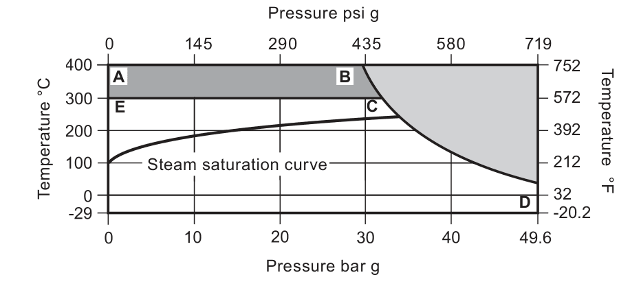
On the chart, A-B-D represents the high-temperature spring and no-spring selections; E-C-D represents the standard spring selection. Do not use the prohibited region. Special testing for lower-temperature operation can be provided at extra cost.
| Designation | Description | Limit |
|---|---|---|
| PN | Body design condition | PN50 |
| PMA | Maximum allowable pressure | 49.6 bar g at 38 °C (719 psi g at 100 °F) |
| TMA | Maximum allowable temperature | 400 °C at 29.4 bar g (752 °F at 426 psi g) |
| Minimum allowable | Minimum allowable temperature | -29 °C (-20.2 °F) |
| PMO | Maximum operating pressure | 49.6 bar g at 38 °C (719 psi g at 100 °F) |
| TMO | Metal seat with standard spring | 300 °C (572 °F) |
| TMO | Metal seat with high-temperature spring | 400 °C (752 °F) |
| TMO | Metal seat without spring | 400 °C (752 °F) |
| TMO | Viton seat | 205 °C (401 °F) |
| TMO | EPDM seat | 120 °C (248 °F) |
| Minimum operating | Metal seat | -29 °C (-20.2 °F) |
| Minimum operating | Viton seat | -25 °C to +205 °C (-13 °F to +401 °F) |
| Minimum operating | EPDM seat | -40 °C to +120 °C (-40 °F to +248 °F) |
| Vacuum | Full vacuum service | Safe under full vacuum conditions |
| Hydraulic test | Maximum cold hydraulic test pressure | 76 bar g (1102 psi g) |
The pressure and temperature limits are conditional. Special testing for lower-temperature operation can be provided at extra cost; consult the manufacturer before ordering.
Dimensions and approximate weights
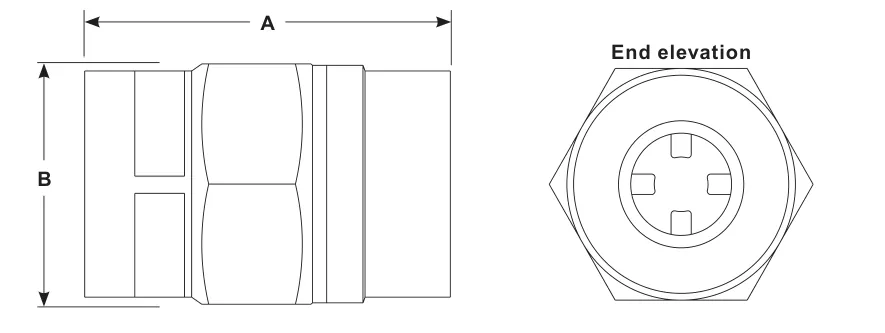
| Size | A socket weld | A screwed | B A/F | Weight |
|---|---|---|---|---|
| 1/2 inch | 50 (1.97) | 51 (2.01) | 34 (1.34) | 0.2 (0.44) |
| 3/4 inch | 55 (2.17) | 57 (2.24) | 41 (1.61) | 0.3 (0.66) |
| 1 inch | 67 (2.64) | 68 (2.68) | 50 (1.97) | 0.5 (1.1) |
| 1 1/4 to 2 inch | 100 (3.94) | 100 (3.94) | 80 (3.15) | 2.0 (4.4) |
Kv values
| Size | 1/2 inch | 3/4 inch | 1 inch | 1 1/4 inch | 1 1/2 inch | 2 inch |
|---|---|---|---|---|---|---|
| Kv | 4.4 | 7.5 | 12 | 30 | 35 | 35 |
For conversion: Cv (UK) = Kv x 0.963. Cv (US) = Kv x 1.156.
Opening pressures
Differential pressures at zero flow for standard and high-temperature springs are shown below in mbar (mpsi).
| Flow direction | All sizes |
|---|---|
| Upward | 25 (0.36 psi) |
| Horizontal | 22.5 (0.33 psi) |
| Downward | 20 (0.29 psi) |
Where a lower opening pressure is required, a valve without a spring can be installed in a vertical pipe with bottom-to-top flow.
| Without spring, upward flow | 1/2 inch | 3/4 inch | 1 inch | 1 1/4 to 2 inch |
|---|---|---|---|---|
| Opening pressure, mbar | 3.0 (0.044 psi) | 2.5 (0.036 psi) | 4.0 (0.058 psi) | 6.5 (0.094 psi) |
Heavy-duty springs have an opening pressure of approximately 700 mbar (10.2 psi).
Pressure loss diagram
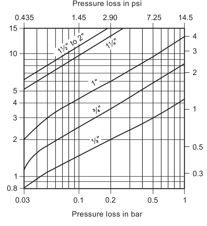
The pressure-loss chart applies to an open, spring-loaded valve at 20 °C (68 °F) with horizontal flow. With vertical flow, insignificant deviations occur only within the range of partial opening. The curves are valid for water at 20 °C (68 °F).
For another fluid, calculate the equivalent water volume flow and use that value in the graph:
Vw = sqrt(ρ / 1000) x V
Vw is equivalent water volume flow in l/s or m3/h, ρ is fluid density in kg/m3, and V is fluid volume flow in l/s or m3/h. Pressure-loss information for steam, compressed air and gases is available separately from the manufacturer.
Option markings and applications
| Body marking | Spring | Seat |
|---|---|---|
| N | High-temperature spring | Standard metal seat |
| W | Without spring | Standard metal seat |
| WV | Without spring | Viton seat |
| WE | Without spring | EPDM seat |
| H | Heavy-duty spring | Standard metal seat |
| HV | Heavy-duty spring | Viton seat |
| HE | Heavy-duty spring | EPDM seat |
| V | Standard spring | Viton seat |
| E | Standard spring | EPDM seat |
| No marking | Standard spring | Metal disc and seat |
Viton seats are documented for oil and gas applications and EPDM seats for water applications. Soft-seat options are for screwed connections only.
How to order
Specify the quantity, DCV41 model, nominal size, connection type, spring and seat selection, and any certification or inspection requirements. An example is one DCV41 in an austenitic stainless steel body with a 1/2 inch screwed BSP connection, Viton soft seat and body certification to EN 10204 3.1.
Safety, installation and maintenance summary
Fit the valve in accordance with the flow-direction arrow. A spring-loaded valve can be installed in any plane. A valve without a spring must be installed in a vertical flow line with flow from bottom to top. Refer to the Installation and Maintenance Instructions for the complete safety and installation requirements.
The valve is non-maintainable and no spares are available. If a Viton component has been exposed to approximately 315 °C (599 °F) or higher, it may have decomposed and formed hydrofluoric acid; follow the disposal precautions in the installation instructions.
Installation and Maintenance Guide
- Safety information
- General product information
- Installation
- Commissioning
- Operation
- Maintenance
- Spare parts
Read the safety information before installation, commissioning, use or maintenance. This guide must be used with the product name-plate and TI-P601-18.
1. Safety information
Safe operation can only be guaranteed when the product is properly installed, commissioned, used and maintained by qualified personnel in compliance with these operating instructions. General installation and safety instructions for pipeline and plant construction, and the proper use of tools and safety equipment, must also be followed.
1.1 Intended use
Use the Installation and Maintenance Instructions, name-plate and Technical Information Sheet to check that the DCV41 is suitable for the intended application. The product is designed for steam, compressed air, water and other industrial fluids in the applicable Group 2 categories of the European Pressure Equipment Directive 2014/68/EU.
| Product size | Group 2 gases | Group 2 liquids |
|---|---|---|
| DN15 to DN25 | SEP | SEP |
| DN32 | SEP | SEP |
| DN40 to DN50 | Category 1 | SEP |
- Check material suitability, pressure and temperature, including the maximum and minimum values.
- If the product operating limits are lower than the system limits, provide a safety device to prevent dangerous overpressure or overtemperature.
- Determine the correct installation situation and fluid-flow direction.
- Consider external stresses from the connected system and take precautions to minimise them.
- Remove protection covers from connections and protective film from name-plates before installation where appropriate.
- Confirm fluid compatibility with the equipment materials before use.
1.2 to 1.12 Access, hazards and working controls
- Provide safe access and a guarded working platform where necessary. Arrange suitable lifting equipment for heavy products.
- Provide adequate lighting, especially for detailed or intricate work.
- Identify the pipeline contents and any previous contents, including flammable or hazardous substances and extreme temperatures.
- Assess explosion risk, lack of oxygen, dangerous gases, hot surfaces, fire hazards during welding, excessive noise and moving machinery.
- Consider the effect of isolation or other work on the complete system. Isolation valves must be opened and closed gradually to avoid system shocks.
- Isolate pressure and safely vent the system to atmospheric pressure. Consider double isolation, bleed arrangements and locking or labelling of closed valves. Do not assume that the system is depressurised because a gauge reads zero.
- Allow temperature to normalise after isolation. Use protective clothing, including eye protection, when required by the hazard assessment.
- Have suitable tools and consumables available. Use only genuine replacement parts if replacement parts are specified for the wider system.
- Assess protection against chemicals, high or low temperature, radiation, noise, falling objects and eye or face hazards.
- All work must be carried out or supervised by a competent person. Follow any permit-to-work system and provide warning notices or a safety assistant where needed.
- Assess manual-handling risks and use an appropriate handling method for the load and working environment.
1.13 to 1.16 Residual hazards, freezing, disposal and returns
- In normal use the external surface may be very hot; at the maximum permitted operating conditions some surfaces may reach 300 °C (572 °F).
- The product is not necessarily self-draining. Take care when dismantling or removing it from an installation.
- Protect the product against frost damage where it may be exposed to temperatures below freezing.
- The product is recyclable. Follow national and local disposal regulations and the current product-compliance information.
- If a Viton component has been exposed to a temperature approaching 315 °C (599 °F) or higher, it may have decomposed and formed hydrofluoric acid. Avoid skin contact and inhalation of fumes. Follow the specified disposal controls.
- When returning a product, provide written information about contamination residues, mechanical damage and any identified hazardous substances, including relevant safety data sheets.
2. General product information
2.1 Description
The DCV41 is an austenitic stainless steel disc check valve with screwed or socket-weld end connections. It prevents reverse flow in process lines, hot-water systems, steam systems, condensate systems and other compatible services. Viton seats are available for documented oil and gas applications, and EPDM seats are available for documented water applications. Soft seats are for screwed connections only.
Standard shut-off conforms to EN 12266-1 Rate E. Soft-seat versions provide Rate A shut-off when differential pressure exists. A heavy-duty spring is available for boiler feedwater check applications with the documented seat arrangement. A high-temperature spring is available for operation up to 400 °C within the pressure-temperature limits.
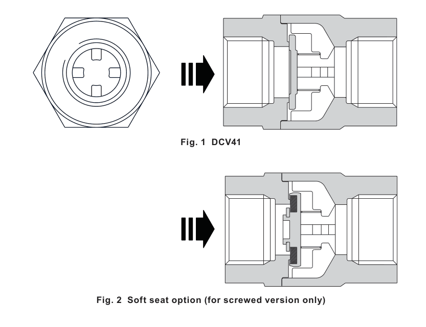
Option markings
| Body marking | Spring | Seat |
|---|---|---|
| N | High-temperature spring | Standard metal seat |
| W | Without spring | Standard metal seat |
| H | Heavy-duty spring | Standard metal seat |
| V | Standard spring | Viton seat |
| E | Standard spring | EPDM seat |
| No identification | Standard spring | Metal disc and seat |
Further combinations are identified in the technical information and on the product marking. Special testing for lower-temperature operation can be provided at extra cost; consult the manufacturer.
2.2 Sizes and pipe connections
Available sizes are 1/2, 3/4, 1, 1 1/4, 1 1/2 and 2 inch. Connections are screwed BSP T Rp to ISO 7-1, screwed NPT to ASME B 1.20.1, or socket weld to ASME B 16.11 Class 3000.
2.3 Pressure and temperature limits
| Condition | Limit |
|---|---|
| Body design condition | PN50 |
| PMA / PMO | 49.6 bar g at 38 °C (719 psi g at 100 °F) |
| TMA | 400 °C at 29.4 bar g (752 °F at 426 psi g) |
| Minimum allowable temperature | -29 °C (-20 °F) |
| TMO, metal seat and standard spring | 300 °C (572 °F) |
| TMO, high-temperature spring or no spring | 400 °C (752 °F) |
| TMO, Viton seat | 205 °C (401 °F) |
| TMO, EPDM seat | 120 °C (248 °F) |
| Minimum operating, metal seat | -29 °C (-20 °F) |
| Minimum operating, Viton seat | -25 °C to +205 °C (-13 °F to +401 °F) |
| Minimum operating, EPDM seat | -40 °C to +120 °C (-40 °F to +248 °F) |
| Cold hydraulic test | 76 bar g (1102 psi g) maximum design test pressure |
The product is safe under full vacuum conditions. Check the complete pressure-temperature relationship for the selected seat and spring before use.
3. Installation
Before installation, observe all safety information in Section 1. Use the name-plate and Technical Information Sheet to confirm suitability.
- Check materials, pressure and temperature and their maximum values. If the product operating limit is lower than the system limit, ensure that a safety device is included to prevent overpressurisation.
- Determine the correct installation situation and direction of fluid flow.
- Remove protective covers from all connections.
- Fit the DCV41 in accordance with the arrow showing the correct flow direction. When fitted with a spring it can be installed in any plane. When supplied without a spring it must be fitted in a vertical flow line with flow from bottom to top.
- Do not use a disc check valve where heavily pulsating flow exists, such as close to a compressor.
3.5 Kv values
| Size | 1/2 inch | 3/4 inch | 1 inch | 1 1/4 inch | 1 1/2 inch | 2 inch |
|---|---|---|---|---|---|---|
| Kv | 4.4 | 7.5 | 12 | 30 | 35 | 35 |
For conversion: Cv (UK) = Kv x 0.97. Cv (US) = Kv x 1.17.
3.6 Opening pressures in mbar
Differential pressures at zero flow for standard and high-temperature springs:
| Flow direction | 1/2 inch | 3/4 inch | 1 inch | 1 1/4 to 2 inch |
|---|---|---|---|---|
| Upward | 25 | 25 | 25 | 25 |
| Horizontal | 22.5 | 22.5 | 22.5 | 22.5 |
| Downward | 20 | 20 | 20 | 20 |
Where a lower opening pressure is required, a valve without a spring can be installed in a vertical pipe with bottom-to-top flow.
| Without spring, upward flow | 1/2 inch | 3/4 inch | 1 inch | 1 1/4 to 2 inch |
|---|---|---|---|---|
| Opening pressure, mbar | 3 | 2.5 | 4 | 6.5 |
4. Commissioning
After installation, ensure that the system is fully functioning. Test alarms and protective devices. Open isolating valves slowly.
5. Operation
Disc check valves open under fluid pressure and close by spring force as soon as flow ceases and before reverse flow occurs.
6. Maintenance
This product is non-maintainable.
7. Spare parts
This product is non-maintainable. It has a fully welded construction and therefore no spares are available.
7.1 How to order a new product
Example: one DCV41 in an austenitic stainless steel body with a 1/2 inch BSP T Rp screwed connection, certification to EN 10204 3.1 for the body and a Viton soft seat.