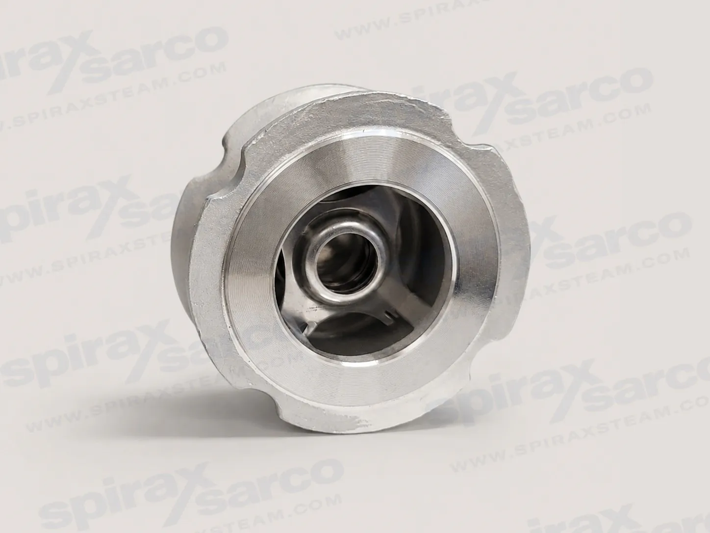
Spirax Sarco DCV4 stainless steel disc check valve
The Spirax Sarco DCV4 is a compact, wafer-pattern disc check valve for process pipework, hot-water circuits, steam services and condensate systems. It mounts between ANSI 150 or ANSI 300 flanges and covers DN15, DN20, DN25, DN40, DN50, DN80 and DN100. Its austenitic stainless steel pressure-retaining parts make it a practical choice where an engineer needs reverse-flow protection in a short face-to-face envelope, with the installation geometry based on EN 558 Part 2, Series 52.
DCV4 is not one universal configuration for every fluid and temperature. The metal-seated standard arrangement is intended for steam service, while fluorocarbon and EPDM soft-seat options address different media and temperature ranges. Spring selection also changes the operating envelope and permitted orientation. A sound selection therefore starts with the actual fluid, pressure, temperature, required opening differential, flange class and pipe orientation rather than the nominal size alone.
How the wafer disc mechanism works
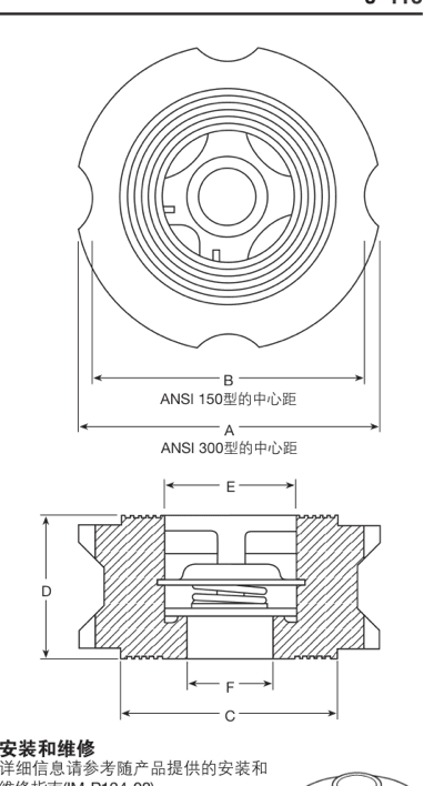
Forward fluid pressure acts on the disc and opens the flow path. As forward flow falls, spring force moves the disc towards its seat before reverse flow can develop. This direct axial movement gives the Spirax Sarco DCV4 a compact form between mating flanges and avoids the long body associated with many conventional check-valve arrangements. The result is useful where installation length matters, provided the selected spring and seat are compatible with the duty.
The spring is also central to orientation and opening behaviour. A spring-loaded DCV4 may be installed in any orientation when the body arrow follows the intended flow direction. A no-spring valve has a much lower opening differential, but it is restricted to vertical pipework with upward flow. The technical information lists typical zero-flow opening differentials for vertical-up, horizontal and vertical-down installations, so orientation should be fixed before the final spring arrangement is ordered.
Materials, seats and spring choices
The Spirax Sarco DCV4 valve body is ASTM A351 CF3M austenitic stainless steel and the standard metal disc is ASTM A276 316 stainless steel. The spring retainer is 316 stainless steel, while the standard spring is a 316 stainless steel component and the high-temperature spring is Nimonic 90 nickel alloy. This defined material set supports traceable engineering review; EN 10204 3.1 material certification can be requested when it is specified with the order.
The standard metal seat is the starting point for steam. A fluorocarbon soft seat is available for oil, air and gas duties within its verified temperature range of -15 to 250 degrees C. The EPDM soft seat is intended for water service and is limited to -29 to 150 degrees C. These options must not be treated as interchangeable: chemical compatibility, temperature and the required shut-off performance all need to be checked for the actual medium.
Spring choices include the standard spring, a high-temperature spring and a no-spring arrangement. The standard spring has a maximum operating point of 300 degrees C at 31.5 bar g. The high-temperature and no-spring arrangements can reach 400 degrees C at 29 bar g. Those figures describe pressure-temperature boundary points rather than separate maximums that can be combined freely. A heavy-spring option is also identified at approximately 700 mbar opening differential; its suitability should be confirmed against the intended hydraulic duty before ordering.
Operating envelope and sizing context
The Spirax Sarco DCV4 body is designed to ASME 300 conditions. The published maximum allowable and maximum operating pressure is 49 bar g at 37 degrees C, while the maximum allowable temperature is 400 degrees C at 29 bar g. The minimum permitted temperature for the body and standard metal disc is -29 degrees C. The cold hydraulic test pressure is 76 bar g. Selection must remain inside the complete pressure-temperature envelope for the chosen spring and seat, not just below one headline pressure or temperature value.
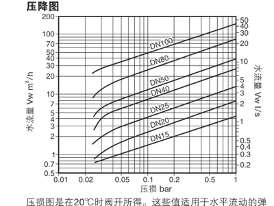
Published Kv values rise from 4.4 at DN15 to 150 at DN100. They are useful for preliminary comparison, but valve size should be checked against the required flow, available differential pressure and the source pressure-drop information. The published pressure-drop curves are based on water at 20 degrees C with the valve open and a spring-loaded valve in horizontal flow. For other fluids, the technical sheet requires conversion to equivalent water flow before the graph is used.
The valve is not suitable for severely pulsating flow, including locations close to a compressor. This is a service boundary rather than an installation preference. Where pulsation, rapid cycling or an unusually low opening pressure is expected, the duty should be reviewed before DCV4 is specified.
Application and installation planning
Typical qualifying duties include preventing reverse flow in process lines, hot-water circuits, steam mains and condensate return pipework. The stainless steel body and multiple seat options broaden the range of compatible services, but they do not replace a fluid-compatibility assessment. Steam generally points to the standard metal seat; water may lead to EPDM; oil, air or gas may lead to the fluorocarbon option. Temperature and chemical exposure can rule out an otherwise attractive soft seat.
The installer must provide the mating flanges, bolts or studs and nuts. The valve must be centred between compatible ANSI 150 or ANSI 300 flanges, and the flow arrow must agree with the intended direction. Spring-loaded configurations allow more freedom in pipe orientation; no-spring configurations do not. The technical source also states that no spare parts are available, so lifecycle planning should treat the valve as a replaceable assembly rather than assume an internal repair kit will be available.
Products containing fluorocarbon components require special end-of-life care. If such material has been exposed near 315 degrees C or above, it may decompose and form hydrofluoric acid. Skin contact and inhalation must be avoided, and disposal must follow the manufacturer's safety guidance. This warning matters even if the normal selected operating range is lower, because it addresses abnormal thermal exposure and safe handling after service.
What to confirm before ordering
Nominal size: DN15, DN20, DN25, DN40, DN50, DN80 or DN100.
Mating flange class: ANSI 150 or ANSI 300.
Fluid, operating pressure and temperature across the full duty cycle.
Metal, fluorocarbon or EPDM seat, including chemical compatibility and leakage expectation.
Standard, high-temperature, heavy or no-spring arrangement and the required opening differential.
Pipe orientation and flow direction, especially for a no-spring valve.
Whether EN 10204 3.1 material certification or optional leakage testing is required.
Engineers comparing this model with other Spirax Sarco disc check valves should use the fluid, flange standard, pressure-temperature envelope, seat material and opening differential as the main selection criteria. The DCV4 page covers only DCV4; related models are separate products and are not included in this page's inquiry scope.