AE30 Liquid system automatic air exhaust valve

AE30

AE30 Liquid system automatic air exhaust valve

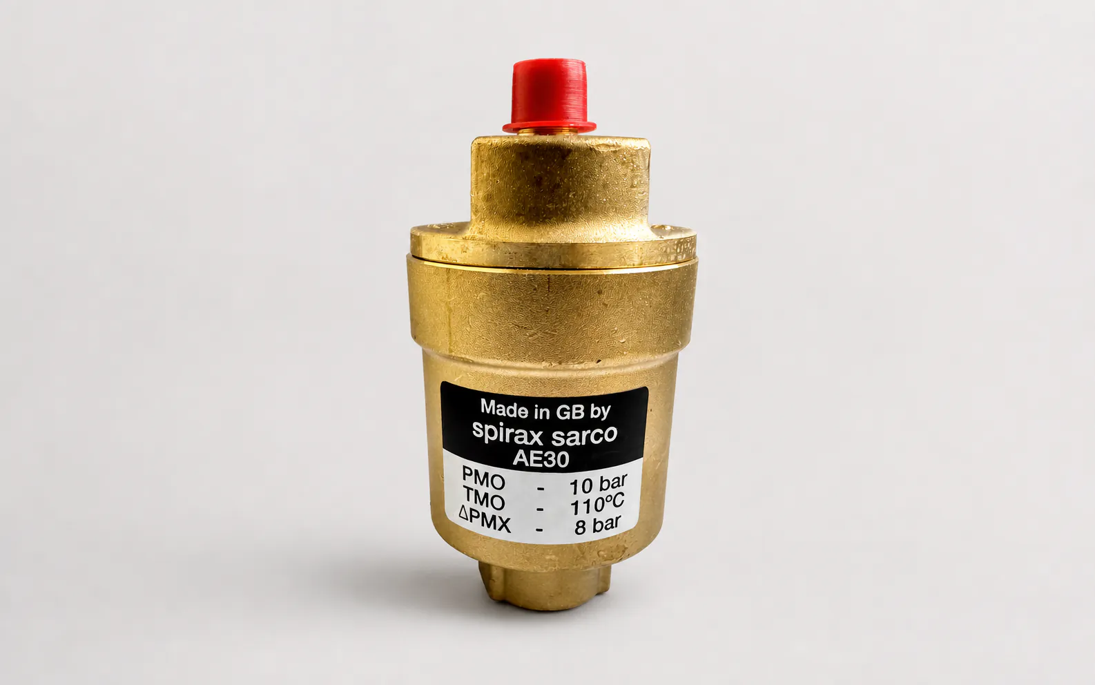
The AE30 series automatically removes air from hot- and cold-water liquid systems. View models and connections, pressure/temperature limits, free air capacity, installation, commissioning, maintenance, spares and ordering information.

Specification

AE30 Key points for selection and use

Spirax Sarco AE30 is for hot and cold water liquid systems automatic air vents for liquid systems, can automatically remove accumulated air at high points in the system. AE30A and AE30C come with check valves, AE30B and AE30C are equipped with a three-way locking mechanism.

  • Applicable systems:For hot and cold water liquid systems, the minimum liquid specific gravity is 0.926.

  • Work restrictions:The maximum working pressure is 10 bar g (110℃), the maximum working temperature is 110℃, and the maximum working pressure difference is 8 bar g (110℃).

  • Installation direction:The valve body must be installed vertically with the inlet at the bottom, and the outlet should be led to a safe and visible discharge position; please contact us if you need engineering support installation and commissioning services.

  • Maintenance safety:Before disassembly, the equipment must be isolated, confirm that the pressure has been completely released, and wait for the temperature to drop to a safe range; maintenance requirements can be found in repair and maintenance services.

Introduction

AE30 Automatic air vent valve designed for use with liquid systems. The valve body and bonnet are made of a special copper alloy that is zinc-free and corrosion-resistant (DZR).

Available models

AE30

Air exhaust valve

AE30A

Air exhaust valve with check valve

AE30B

Air exhaust valve with lock

AE30C

Air exhaust valve with check valve and lock

The AE30B and AE30C feature a unique three-way locking system that ensures the valve is open, closed or used as a regular ball valve. Spirax Sarco can provide special keys to control the operation of this valve.

Standard

This product complies with the European Pressure Equipment Directive 97/23/EC. Stencils available upon request.

Certificate

Manufacturer's test reports are available for this product. If you need a certificate, please indicate this when ordering.

Caliber and pipe connections

AE30, AE30A: Inlet 1/2" internal thread, outlet 1/4" external thread BSP or NPT.

AE30B, AE30C: inlet 1/2" external thread, outlet 1/4" external thread BSP.

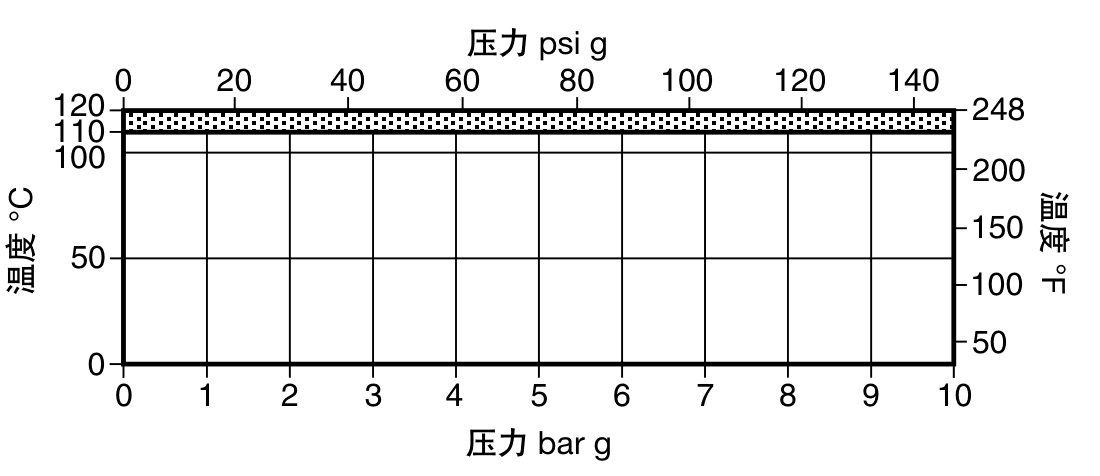
pressure/temperature control

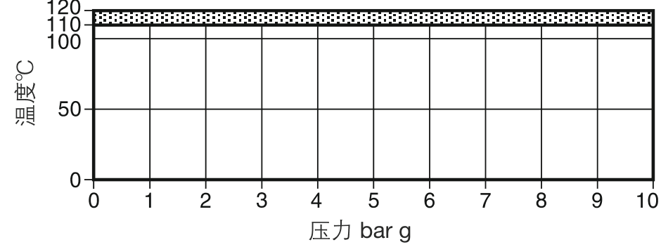
Pressure temperature control range chart

Shaded areas indicate areas where use of this product may cause damage to internal components.

Valve body design conditions

PN10

PMA - maximum allowable pressure

10 bar g @ 120℃

TMA - maximum allowable temperature

120℃ @ 10 bar g

minimum allowable temperature

-10℃

PMO maximum working pressure

10 bar g @ 110℃

TMO maximum operating temperature

110℃

PMX maximum working pressure difference

8 bar g @ 110℃

Minimum operating temperature

0℃

Design maximum cold hydraulic test pressure

15 bar g

Minimum liquid specific gravity

0.926

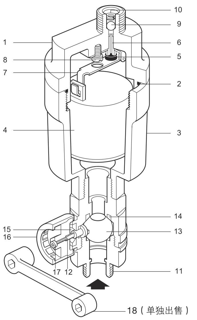
AE30 Automatic air exhaust valve sectional structure diagram

Optional accessories

Locking Key 18 (sold separately).

Material

serial number

parts

Material

1

valve cover

DZR Copper Alloy, BS 2872 CZ 132

2

Bonnet O-ring

Green fluorinated rubber 75

3

valve body

DZR Copper Alloy, BS 2872 CZ 132

4

float

Acetal co hostafom / stainless steel

5

Valve cone

EPDM or pure Viton (IRHD 50-55)

6

valve seat

Stainless steel, BS 970 431 S29

7

Bracket/Bar Assembly

Stainless steel, BS1449 304 S11

8

Bolt

Stainless steel,BS 4183 18/8

9

Check valve

Stainless Steel, ANSI 440B

10

circlip

Stainless steel, BS 970 302 S25

11

Lock body

DZR Copper Alloy, BS 2872 CZ 2132

12

Lock stem

Cr.DZR Carbide, BS 2874 CZ 2132

13

ball

Cr.DZR Carbide, BS 2874 CZ 2132

14

seal

Pure PTFE

15

Stem seal

Pure PTFE

16

outer cover

polyethylene

17

Bolt

steel

18

lock key

Ductile Iron, BS 2789

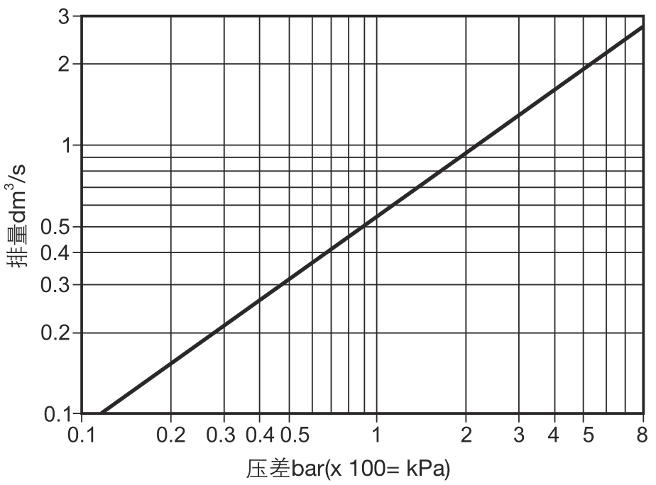
free displacement

Air temperature 16℃

Free displacement curve at air temperature 16℃

If the air temperature is not 16℃, it can be corrected by multiplying the displacement in the figure by the following formula.

289 / (273 + T) (T is the actual temperature)

Assume that the air temperature is equal to the water temperature.

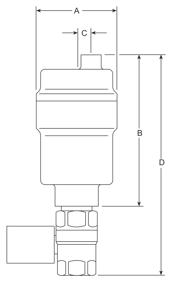
Dimensions/weight (Approximate) Unit: mm/kg

Model

A

B

C

D

weight

AE30, AE30A

56

105

10

-

0.7

AE30B, AE30C

56

105

10

155

0.9

AE30 Series Dimensions Diagram

Safety information, installation and maintenance

For detailed information, please refer to the installation and maintenance guide IM-P017-08 provided with the product.

Installation

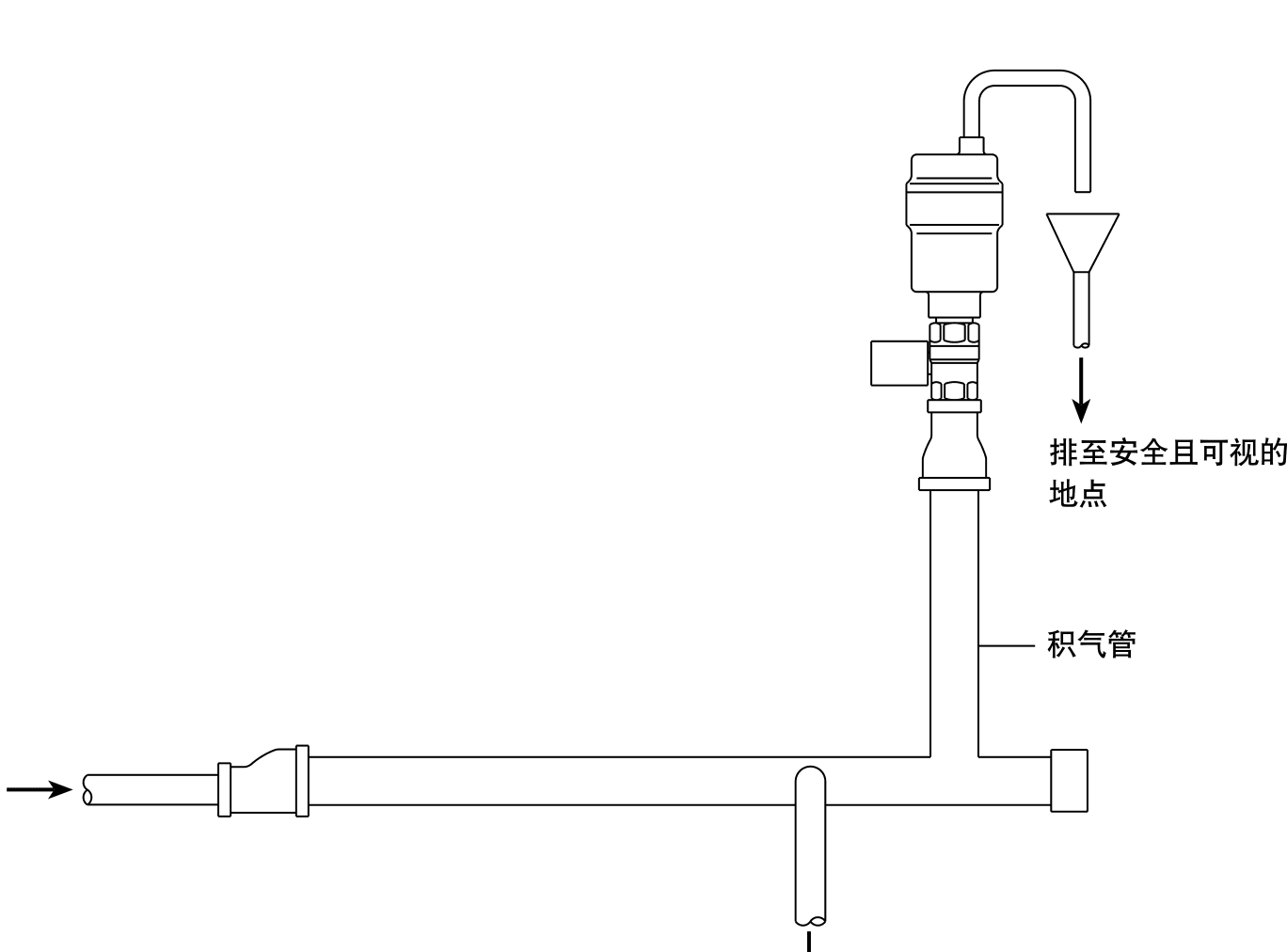
Automatic air bleed valves must be installed vertically with the inlet at the bottom. It is recommended that the outlet be connected to a drainage pipe and discharged to the trench.

order

Example: 1 - Spirax Sarco 1/2" AE30C Automatic air vent valve with check valve and locking device, BSP threaded connection.

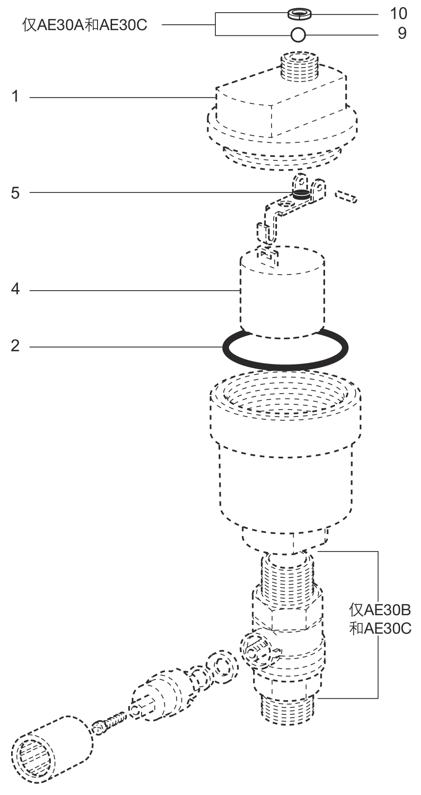
Spare parts

As shown in the figure, the solid line parts are available spare parts, and the dotted line parts are not included in the scope of supply.

Spare parts available

Maintenance components include: cone, float, bonnet O-ring, check ball, check circlip

2, 4, 5, 9, 10

Note

If you have the earlier products of the AE30 series AE30 and AE30CV which have an operating range of 0-3 bar, then the AE30, A, B and C spare parts will work but will not allow you to adjust their operating range to 0-8 bar pressure. But if you have AE30H and AE30HCV which work at 3-8 bar, you have to use earlier spare parts.

Order spare parts

Order spare parts according to the above table and indicate the caliber and model of the automatic air exhaust valve. Example: 1 - 1/2" Spirax Sarco AE30A Repair kit for automatic air exhaust valve.

AE30 Spare parts diagram

parts

mm or

Nm

1

30

10 - 12

8

Cabochon head M4 x 6

Data sources and scope of application

Technical verification basis:Spirax Sarco product technical information TI-P017-07, and installation and maintenance guide IM-P017-08.

Applicable models:AE30, AE30A, AE30B and AE30C. Data publisher: Spirax Sarco China; Page update date: 2026-07-12.

Selection, installation and maintenance should be based on actual system conditions and the latest version of the technical documents provided with the product.

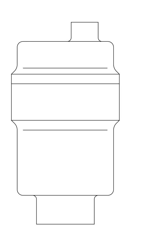
AE30 Schematic diagram of automatic air exhaust valve

1. Safety information

Compliance with the operating instructions and correct installation, commissioning, and maintenance by professional and qualified personnel are necessary conditions for the safe operation of this product. Installation must comply with installation and safety guidelines for piping and plant construction, and the correct use of tools and necessary safety equipment.

1.1 Scope of use

Refer to this guide, nameplate and technical documentation to ensure the product is suitable for the intended operating conditions. AE30 All models are classified under the Pressure Equipment Directive with "-" for Class 1 and Class 2 gases, and SEP for Class 1 and Class 2 liquids.

The product is designed for use with Pressure Equipment Directive Class 2 fluids including steam, air and water/condensate. Please consult Spirax Sarco for use with other fluids. Confirm that the material, maximum and minimum pressures, and temperatures are within the design range, and that the installation direction is correct.
1.2 Operability

Make sure there is enough operating space after the product is installed; prepare a safe working platform and lifting equipment if necessary.

1.3 Lighting

Ensure adequate lighting, especially when performing delicate or complex operations.

1.4 Hazardous fluids or gases in pipelines

Confirm the current or possible fluids in the pipeline in advance, and be wary of flammable, health-threatening, and high- and low-temperature substances.

1.5 Hazardous working environment

Evaluate risks such as explosions, lack of oxygen, hazardous gases, high and low temperatures, hot surfaces, welding fires, excessive noise, and moving equipment.

1.6 Working system

Before operating a shut-off valve or electrical switch, understand the entire system to make sure it will not put other system parts or personnel at risk. Slowly open and close the stop valve to prevent system shock.

1.7 Pressure system

Isolate and completely depressurize the system. Double stop valves can be used to isolate and lock or tag out; returning the pressure gauge to zero does not mean that the system has been completely depressurized.

1.8 Temperature

Separate the product and allow to cool to room temperature. When Viton reaches or exceeds 315°C, it will decompose to form hydrogen fluoride gas; when PTFE reaches or exceeds 260°C, toxic fumes will be produced. Avoid skin contact or inhalation, and prohibit smoking in areas where PTFE is handled.

1.9 Tools and spare parts

Prepare suitable tools and spare parts before operation and only use genuine Spirax Sarco spare parts.

1.10 Protective clothing

Equip operators and nearby personnel with protective clothing based on chemical substances, high and low temperatures, radiation, noise, falling objects, and eye and facial risks.

1.11 Work permit

All work must be done by or under the supervision of competent personnel. Comply with the on-site work permit system, arrange safety assistants when necessary and post warning instructions.

1.12 Transportation

Manual handling of large or heavy products can result in injuries, especially back injuries. Use appropriate handling procedures based on workload, personnel, heavy objects, and site conditions.

1.13 Waste heat

The surface of the product may be very hot during normal use, reaching 100°C at the maximum allowable operating temperature. The product is not self-draining and care must be taken when dismantling or moving it.

1.14 Freeze

Provides necessary frost protection for non-self-draining products when ambient temperatures fall below freezing.

1.15 Processing

Unless otherwise stated, products are recyclable. Viton should be buried in accordance with local regulations or incinerated under compliance conditions; PTFE can only be disposed of in accordance with approved methods and must not be incinerated. It should be stored in isolation and handed over to a garbage disposal station.

1.16 Returns

Returns must provide written information on residual contamination, mechanical damage and potential health, safety or environmental hazards, together with relevant health and safety data.

2. Product information

2.1 Introduction

The AE30 Series liquid system automatic air vents are designed for use in hot and cold water systems. The valve body and bonnet are made of a special copper alloy that has been treated to resist corrosion (DZR).

Model

Configuration

AE30

Standard air exhaust valve

AE30A

Standard air bleed valve with check valve

AE30B *

Standard air exhaust valve with locking

AE30C *

Standard air bleed valve with check valve and lock

AE30LV **

Standard air bleed valve with lightweight float

AE30LVA **

Standard air bleed valve with lightweight float and check valve

* The three-way locking system of the AE30B and AE30C can be locked in the normally open or normally closed position, or used as a normal ball valve. Locking levers are purchased separately.

** The lightweight float is suitable for liquids with a specific gravity of not less than 0.7. The Viton valve core is standard and has chemical corrosion resistance.

See TI-P017-07 and TI-P017-16 for additional technical information.

2.2 Caliber and pipe connection

AE30、AE30A、AE30LV、AE30LVA

Inlet 1/2" internal thread, outlet 1/4" external thread, BSP or NPT

AE30B、AE30C

Inlet 1/2" Male thread, Outlet 1/4" Male thread, BSP

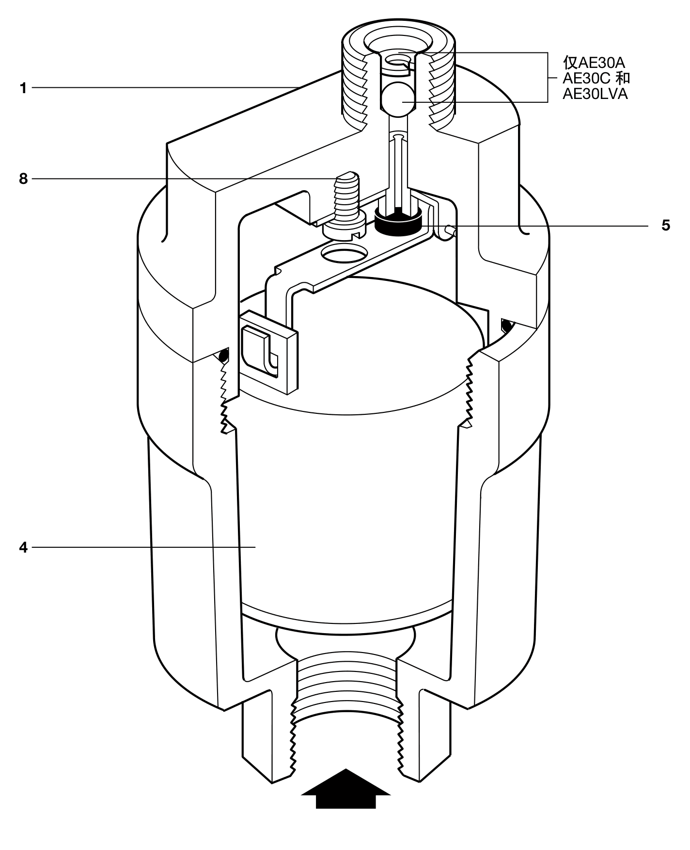
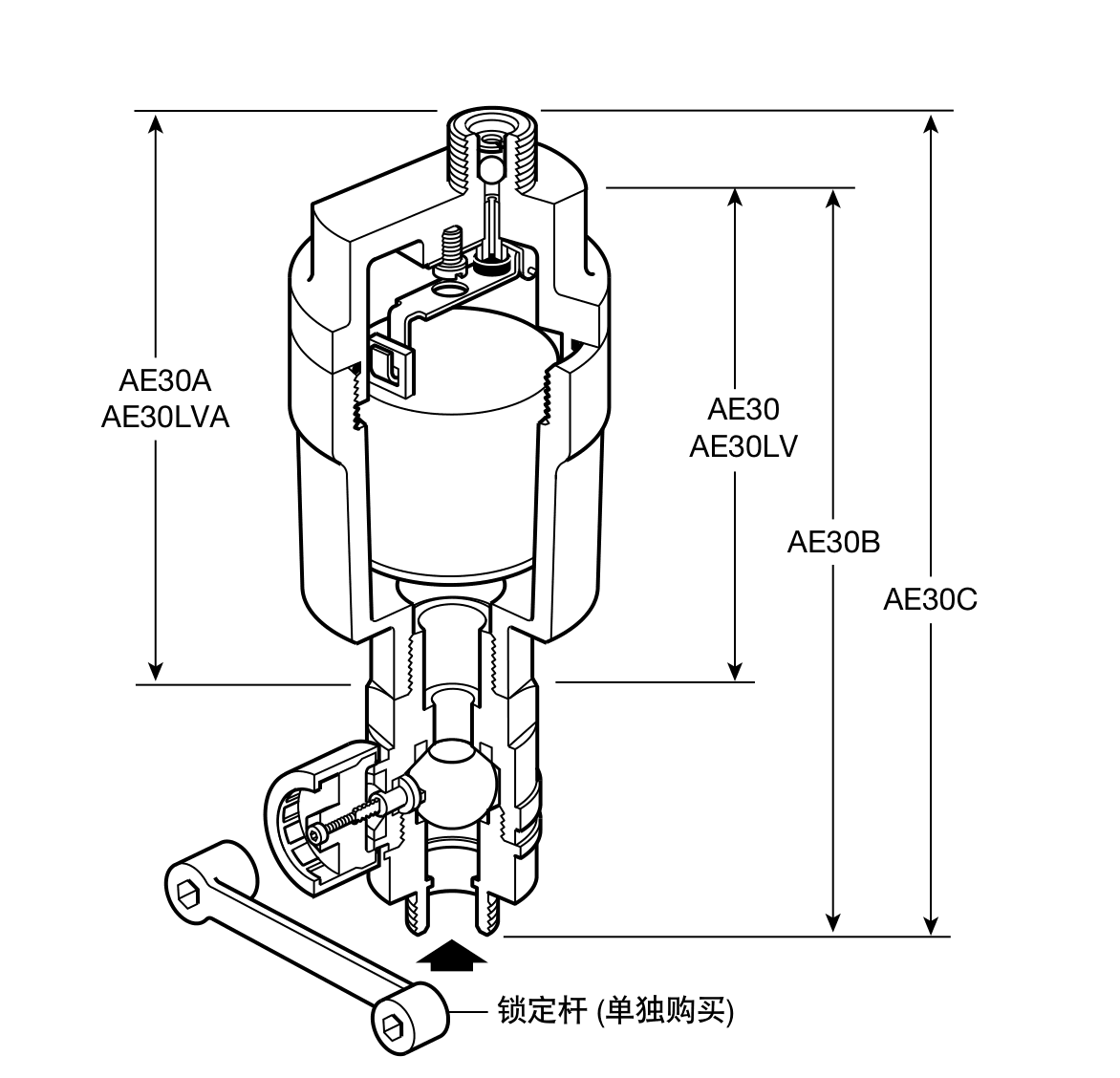
Schematic diagram of structure and height differences of AE30 series models
Figure 1 P0001⟫ Structure and differences among models

2.3 Pressure/Temperature Limitations

AE30 Pressure and temperature operating range chart
It is forbidden to use the shaded area, otherwise the internal parts may be damaged.

Valve body design conditions

PN10

PMA maximum allowable pressure

10 bar g @ 120°C

(145 psi g @ 248°F)

TMA maximum allowable temperature

120°C @ 10 bar g

(248°F @ 145 psi g)

minimum allowable temperature

-10°C

(14°F)

PMO maximum working pressure

AE30 10 bar g @ 110°C

(145 psi g @ 230°F)

AE30LV 10 bar g @ 110°C

(145 psi g @ 230°F)

TMO maximum operating temperature

110°C

(230°F)

DPMX Maximum working pressure difference

AE30 8 bar g @ 110°C

(116 psi g @ 230°F)

AE30LV 3 bar g @ 110°C

(43.5 psi g @ 230°F)

Minimum operating temperature

0°C

(32°F)

Design cold test water pressure

15 bar g

(217 psi g)

Minimum liquid specific gravity

AE30 0.926

AE30LV 0.7

3. Installation

Note:Read Section 1, "Safety Information" carefully before installation. Refer to this guide, nameplate and technical documentation to confirm that the product meets the required operating conditions.

  1. Check maximum values for material, pressure and temperature. If the maximum operating conditions of the product are lower than the system operating conditions, safety devices should be installed to prevent overpressure.

  2. Check whether the installation position and flow direction are correct.

  3. Before installing to steam or other high temperature systems, remove the interface protective sleeve and nameplate protective film.

  4. Automatic air bleed valves must be installed vertically with the inlet at the bottom. It is recommended that the discharge be routed to a safe, visible location with an outlet 1/4" BSP or NPT external thread.

AE30 Typical installation diagram of automatic air exhaust valve
Figure 2 Typical installation

4. Debugging

After installation or repair, make sure the system is functioning properly and test alarms and safety devices.

5. Run

The air bleed valve is open during startup, allowing air to be exhausted through the main valve. When the water arrives, the float rises and a lever mechanism closes the valve.

When more air arrives, the valve expels some of the water and the float drops and opens the valve. After the air is removed, the water level rises and the valve closes again.

When the system is operating under negative pressure, a check valve must be installed to prevent air from entering the system.

The locking type valve uses a standard ball valve with a locking body and has a three-way locking system:

  • working normally

  • locked in open position

  • locked in closed position

The ball valve can be adjusted by the locking lever during normal operation. After removing the plastic valve cover and screws, the valve stem can be rotated to lock the valve in the open or closed position.

6. Maintenance

6.1 Introduction

All work must be carried out by qualified personnel. Prepare the right tools before you start and only use Spirax Sarco spare parts. The air vent valve should be isolated from the pressure system and allowed to cool to room temperature before servicing.

The product has a long service life and usually only requires occasional cleaning of the valve core and seat.

6.2 Clean or replace the valve core and valve seat

  1. Unscrew the bonnet from the valve body (1).

  2. Remove the float (4) from the lever, unscrew the screw (8) in the center of the bonnet, and take out the mechanism.

  3. Remove the float and replace the valve core (5).

  4. Reinstall the mechanism, replace the float on the lever, and screw the assembly back onto the valve body to the recommended torque.

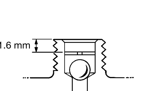
AE30A, AE30LVA and AE30C are equipped with check valves. The check valve is installed at the outlet of the exhaust valve and is held down by a circlip; the circlip should be located below the outlet plane 1.6 mm.

Check valve circlip installation depth 1.6 mm
Figure 3 Check valve installation position
AE30A Repair structure and part number
Figure 4 P0012⟫ Maintenance structure

part number

Tools/Threads

Torque Nm

(lbf ft)

1

30 A/F

10 - 12

7.0 - 8.6

8

Cabin head M4 × 6

2.5 - 2.8

1.8 - 2.0

7. Spare parts

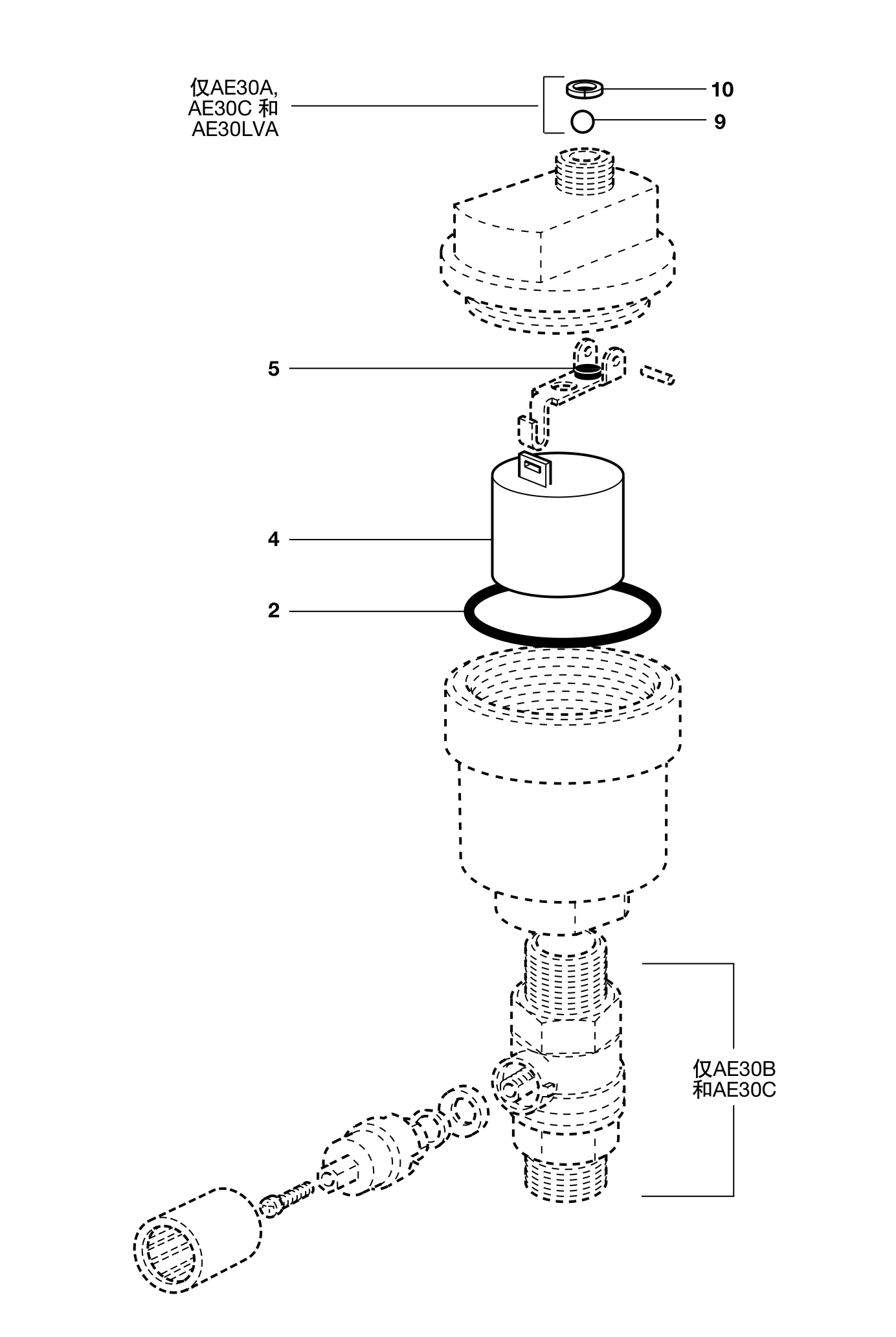
The solid lines in the figure show available spare parts, and the dotted lines are not included in the scope of supply.

Spare parts available

part number

Repair components: bonnet O-ring, float, valve cone, check valve ball, check valve circlip

2、4、5、9、10

Important tips

The AE30 and AE30CV earlier products have an operating range of 0-3 bar, AE30, A, B, C spare parts can be used, but the operating range cannot be adjusted to 0-3 bar. For AE30H and AE30HCV operating at 3-8 bar, older spare parts must be used.

How to order spare parts

Order spare parts as described in the table, and indicate the model and size of the automatic air exhaust valve.

Example:1 - 1/2" Spirax Sarco AE30A Automatic Air Bleed Valve Repair Kit.

AE30 series spare parts available, exploded view and part number
Figure 5 AE30 series spare parts available

Technical documentation

DocumentReferenceLanguageDownload
AE30TI-P017-07-ENEnglishDownload

Installation and maintenance

DocumentReferenceLanguageDownload
AE30IM-P017-08-ENEnglishDownload

Talk to our technical team

Contact Spirax Sarco for product selection, documentation or replacement guidance.