AE14 Automatic Air Vent for Liquid Systems

AE14

AE14 Automatic Air Vent for Liquid Systems

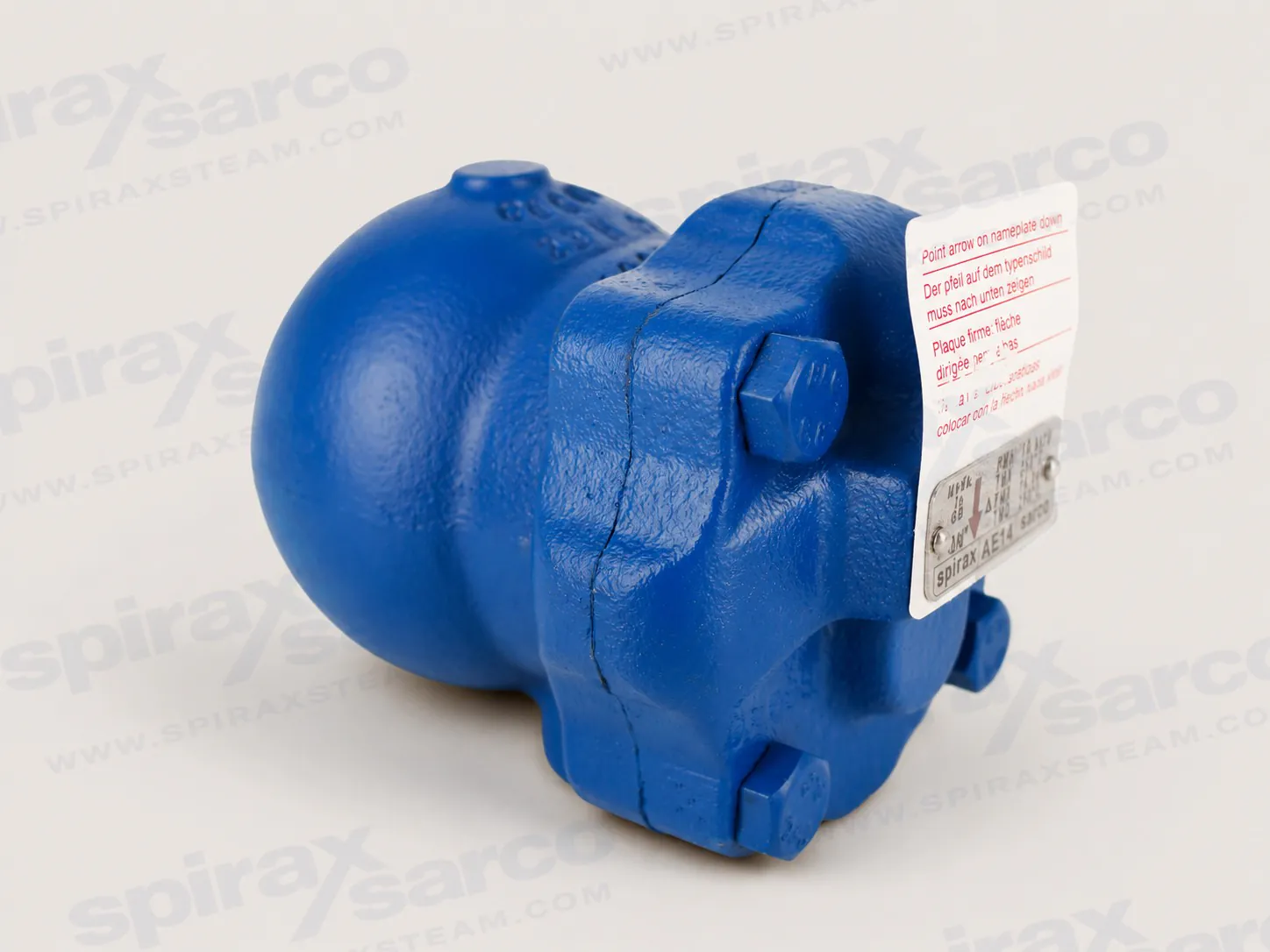
Spirax Sarco AE14 is a maintainable SG iron float-operated automatic air vent with a Viton valve head for removing air and gases from compatible liquid systems.

Specification

Spirax Sarco AE14 automatic air vent for liquid systems

The Spirax Sarco AE14 is a float-operated automatic air vent designed to remove air and other non-condensable gases from liquid systems. The standard AE14 combines an SG iron body and cover with a stainless steel float-and-lever mechanism and a Viton valve head. It is available in 1/2 inch and 3/4 inch screwed connections and is intended for installation at a high point where trapped air can collect. Once installed correctly, the mechanism operates automatically and requires no routine adjustment during start-up or normal service.

Air pockets in water and condensate systems can obstruct circulation, slow heat transfer, increase noise and make commissioning less predictable. Placing an AE14 above the point being vented gives accumulated gas a controlled escape path while the float mechanism closes the valve as water reaches the chamber. The result is a compact, maintainable solution for liquid services where manual venting would be inconvenient or inconsistent.

How the float mechanism works

The operating principle is direct. Air and gas entering the chamber allow the float to remain down, so the lever holds the valve head away from its seat and the gas can discharge. As liquid enters, the float rises and moves the lever until the Viton valve head closes tightly against the stainless steel seat. When another pocket of air reaches the vent, the liquid level falls, the valve reopens and the cycle repeats.

This level-responsive action explains why installation orientation matters. The Spirax Sarco AE14 must be mounted in a vertical plane with its inlet at the bottom so the float arm can rise and fall freely. Tilting the body or supporting it from an unsuitable connection can prevent the mechanism from following the liquid level correctly. The nameplate arrow must point downwards, and the unit should sit above the point from which air is being removed.

Construction and engineering value

The body and cover are SG iron to EN-GJS-400-15. The main seat, seat gasket, float, lever, pivot frame and assembly fasteners use specified stainless steels, while the standard AE14 valve head is Viton. A reinforced exfoliated graphite cover gasket completes the pressure-containing joint. This construction provides a robust serviceable body with corrosion-resistant working parts at the valve mechanism.

Maintainability is an important distinction for a permanently installed air vent. The cover can be removed after the vent has been isolated, depressurised and cooled, allowing access to the float, lever, valve head, seat and pivot components. Maintenance kits, seal kits and replacement valve heads are documented by the manufacturer. Correct spares must always be ordered against both the size and the exact automatic-air-vent type.

Operating envelope

The AE14 body has PN16 design conditions. The published maximum allowable pressure is 16 bar g at 110 C, and the maximum allowable temperature is 250 C at 13.6 bar g. For the standard Viton-seated AE14, the maximum operating pressure is 16 bar g and the maximum operating-temperature boundary is 200 C at 14.5 bar g. These are linked pressure-temperature points rather than separate limits that can be combined arbitrarily.

The minimum allowable and operating temperature is 0 C. The maximum differential pressure is 14 bar and the minimum liquid specific gravity is 0.6. A cold hydraulic test pressure of 24 bar g is stated in the technical information. Final selection therefore needs the actual operating pressure, temperature, fluid density and expected differential pressure, not only the pipe size.

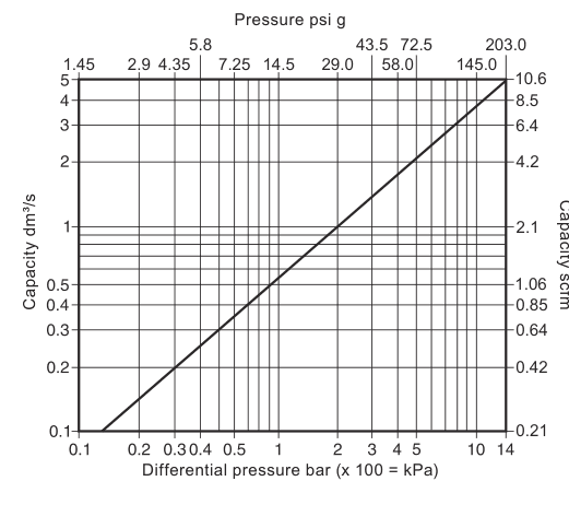
Published capacity is shown against differential pressure in the technical section below. The curve is useful when checking whether the vent can release the expected air load, but it should be read together with the complete operating envelope. A high nominal capacity does not override the pressure-temperature boundary, minimum density requirement or vertical installation rule.

Typical applications and limitations

The Spirax Sarco AE14 is intended for compatible Group 2 water and condensate duties. Typical positions include high points on hot-water circulation systems, water mains, liquid storage and process circuits where air can accumulate. It can also support commissioning by allowing trapped gas to leave as the system fills, then continue venting automatically during normal operation.

Application suitability depends on more than the word "water". The installer must confirm material compatibility, system pressure, temperature, liquid specific gravity and the consequences of a blocked or discharging vent. If the system can exceed the product limits, suitable protective equipment must prevent overpressure or overtemperature. The product is not intended to absorb external pipe stresses, so the surrounding pipework must be aligned and supported independently.

Discharge must be treated as a live process outlet. Air or gas released to atmosphere may reach 100 C, and entrained moisture may also be present. The outlet should be piped to a safe point where personnel and nearby equipment cannot be harmed. The vent is not self-draining in every condition, so frost protection is required where the installation may fall below freezing.

Connection and installation planning

Standard sizes are 1/2 inch and 3/4 inch with screwed BSP or NPT connections. Before installation, confirm that the connection standard matches the prepared pipework, remove all protective covers and check the flow direction. The air vent should be mounted above the vented point, vertically, with its inlet at the bottom. The discharge line should not impose a load that can distort or misalign the body.

Isolation is required for safe maintenance. The standard AE14 does not include an integral inlet stop valve, so the system design must provide external isolation that permits the vent to be depressurised and cooled before its cover is opened. Isolation valves must be operated gradually to avoid system shock, and a zero pressure-gauge reading must not be treated as proof that the isolated section is depressurised.

Commissioning and lifecycle considerations

After installation, verify that the system is fully functional and test any alarms or protective devices affected by the work. No operating adjustment is needed at the vent. During service, investigate leakage, failure to vent or abnormal noise by first checking installation orientation, isolation arrangements, system cleanliness and whether the operating conditions remain inside the published envelope.

Maintenance must be carried out by competent personnel using suitable tools and genuine replacement parts. The cover gasket and main-valve-assembly gasket contain thin stainless steel support rings that can cause injury if handled or discarded carelessly. Joint faces must be clean during reassembly, new gaskets used where specified, fasteners tightened to the published torques and the vent leak-tested as pressure is restored gradually.

Viton requires a specific end-of-life precaution. If a Viton component has been exposed to a temperature approaching 315 C or above, decomposition may form hydrofluoric acid. Skin contact and fume inhalation must be avoided, and disposal must follow applicable regulations and the manufacturer's safety instructions. This is an abnormal exposure warning, not an extension of the AE14 operating temperature range.

What to confirm before ordering

  • Exact model: standard AE14 with Viton valve head.
  • Connection size: 1/2 inch or 3/4 inch.
  • Thread standard: BSP or NPT, with a verified material code for the chosen version.
  • Fluid, operating pressure, temperature, differential pressure and liquid specific gravity.
  • Vertical mounting space, inlet-at-bottom orientation and a safe discharge route.
  • External isolation and access needed for future maintenance.
  • Whether EN 10204 2.2 material certification is required at the time of order.

Engineers comparing automatic air vents and air eliminators should use the actual medium, material compatibility, pressure-temperature range, connection, venting capacity and maintenance strategy as the primary selection criteria. This page and its enquiry options cover AE14 only.

Description and standards

AE14 is the standard float-operated automatic air vent for liquid systems, fitted with a Viton valve head. Its body and cover are SG iron and the complete unit is maintainable. The product complies with applicable EU Pressure Equipment Directive and UK Pressure Equipment (Safety) Regulations requirements and carries the required marking when applicable.

Material certification to EN 10204 2.2 is available. Certification and inspection requirements must be stated when the order is placed.

Sizes and connections

1/2 inch and 3/4 inch screwed BSP or NPT.

Materials

PartMaterialSpecification
BodySG ironEN-GJS-400-15
CoverSG ironEN-GJS-400-15
Cover boltsSteelBS 3692 Gr. 8.8
Cover gasketReinforced exfoliated graphite-
Main valve seatStainless steelBS 970 431 S29
Main valve seat gasketStainless steelBS 1449 304 S11
Main valve assembly screwsStainless steelBS 6105 Cl A2-70
Ball float and leverStainless steelBS 1449 304 S16
Valve headViton-
Pivot frameStainless steelBS 1449 304 S16
Pivot pinStainless steel-

Pressure and temperature limits

Body design conditionsPN16
PMA, maximum allowable pressure16 bar g (232 psi g) at 110 °C (230 °F)
TMA, maximum allowable temperature250 °C (482 °F) at 13.6 bar g (197.3 psi g)
Minimum allowable temperature0 °C (32 °F)
PMO, maximum operating pressure16 bar g (232 psi g)
TMO, maximum operating temperature200 °C (392 °F) at 14.5 bar g (210 psi g)
Minimum operating temperature0 °C (32 °F)
Maximum differential pressure14 bar (203 psi)
Maximum cold hydraulic test pressure24 bar g (348 psi g)
Minimum liquid specific gravity0.6

Selection note: pressure and temperature limits are conditional. Do not combine the maximum pressure and maximum temperature as an unrestricted operating point.

AE14 pressure-temperature operating envelope with B-D boundary
AE14 uses the B-D operating boundary shown in the official pressure-temperature chart.

Dimensions and approximate weight

SizesABCDEFGWeight
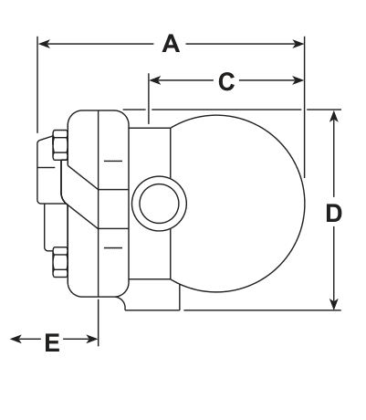
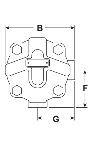
1/2 in and 3/4 in147 mm114 mm80 mm114 mm105 mm60 mm60 mm2.5 kg
AE14 side-view dimensional drawing with A, C, D and E dimensions
AE14 side-view dimensions: A, C, D and E.
AE14 end-view dimensional drawing with B, F and G dimensions
AE14 end-view dimensions: B, F and G.

Air capacity

AE14 air capacity curve plotted against differential pressure in bar and psi
Air capacity against differential pressure. Read the logarithmic axes in the units shown.

Ordering and spares

State the manufacturer, connection size, thread standard, AE14 model, SG iron body and Viton valve head. Available service items include a maintenance kit, seal kit and replacement valve-head packet. Order spares by the published description and state both the size and the exact automatic-air-vent type.

Installation and Maintenance Guide

  1. Safety information
  2. Installation
  3. Commissioning and operation
  4. Maintenance
  5. Recommended torques

1. Safety information

Safe operation depends on correct installation, commissioning, use and maintenance by qualified personnel. Follow the operating instructions, general pipeline and plant-construction requirements, and the site's rules for tools, protective equipment and permits to work.

Suitability and system conditions

  • Confirm from the nameplate and technical information that AE14 is suitable for the intended Group 2 water or condensate duty.
  • Check material compatibility and the complete pressure-temperature range. Fit protective equipment if a malfunction could create overpressure or overtemperature.
  • Determine the correct installation position and flow direction, and remove protective covers from all connections.
  • Do not use the product to carry external pipe stresses. Align and support the system independently.

Before starting work

Provide safe access, suitable lighting, lifting arrangements where needed and protection from surrounding hazards. Consider current and previous pipeline contents, hot surfaces, fire or explosion risk, oxygen deficiency, noise and moving equipment. Assess how isolation affects the entire system, including vents, controls, alarms and protective devices.

Isolate pressure and vent it safely to atmosphere. Consider double isolation, locking and labelling. A gauge reading zero is not proof that the system is depressurised. Allow temperature to normalise, wear suitable protective clothing and follow the permit-to-work system.

Gasket warning: the cover gasket and main-valve-assembly gasket contain thin stainless steel support rings that can cause injury if handled or discarded carelessly.

Viton warning: Viton exposed to a temperature approaching 315 °C (599 °F) or above may decompose and form hydrofluoric acid. Avoid skin contact and fume inhalation. Dispose of affected material only in accordance with the manufacturer's guidance and applicable regulations.

2. Installation

  1. Check the body materials and maximum and minimum pressure-temperature values against the system conditions.
  2. Confirm the intended vent point and the direction of flow.
  3. Remove all protective covers from the screwed connections.
  4. Fit the automatic air vent in a vertical plane above the point being vented, with the inlet at the bottom. The float arm must be able to rise and fall vertically and the nameplate arrow must point downwards.
  5. Pipe the discharge to a suitable safe point. Air or gas discharged to atmosphere may be at 100 °C (212 °F).
  6. Provide suitable external isolation for maintenance of the standard AE14.

Protect the vent from frost where it may be exposed below freezing. Do not allow the outlet pipe to impose excessive force or misalignment on the body.

3. Commissioning and operation

After installation or maintenance, ensure the system is fully functional and test any alarms or protective devices. Restore pressure gradually and inspect the vent and its joints for leakage.

The float-lever valve opens to air and gas and closes tightly to water. Once correctly installed, AE14 requires no start-up or running adjustment. The automatic action accommodates changing air loads as the liquid level in the chamber rises and falls.

4. Maintenance

Maintenance must be performed by a competent person. Isolate the vent from the pressurised system, vent the isolated section safely and allow it to cool. Use suitable tools and genuine replacement parts. Clean all joint faces before reassembly.

Replacing the valve head

  1. Remove the cover bolts and lift off the cover.
  2. Withdraw the pivot pin and release the float and lever from the pivot frame.
  3. Push out the old valve head, fit the replacement and reassemble the float and lever.
  4. Raise and lower the float several times to confirm that the valve head centres correctly on the seat.
  5. Refit the cover with a new cover gasket and tighten the bolts uniformly to the specified torque.
  6. Restore pressure slowly and check for leaks.

Replacing the main valve assembly

  1. Remove the cover, pivot pin, float and lever.
  2. Remove the main-valve-assembly screws and pivot frame.
  3. Unscrew the main valve seat and remove its gasket.
  4. Fit the new seat and gasket and tighten the seat to the specified torque.
  5. Reassemble the float and lever, then check that the valve head centres correctly as the float moves.
  6. Refit the cover with a new gasket, tighten uniformly, restore pressure gradually and leak-test the assembly.
PartTool / sizeTorque
Cover bolts17 A/F, M10 x 3047-50 N m
Main valve seat17 A/F50-55 N m
Main valve assembly screwsPozidrive, M4 x 62.5-3.0 N m

After any maintenance, ensure the complete system is functional and check all disturbed joints for leakage.

Technical information

DocumentReferenceLanguageDownload
AE14TI-P149-01-ENEnglishDownload

Installation and maintenance

DocumentReferenceLanguageDownload
AE14IM-P149-06-ENEnglishDownload

Talk to our technical team

Contact Spirax Sarco for product selection, documentation or replacement guidance.