Compare HV3 with other isolation options
Return to the wider isolation valve range when you need to compare HV3 stop valves with ball valves and bellows sealed shut-off families.

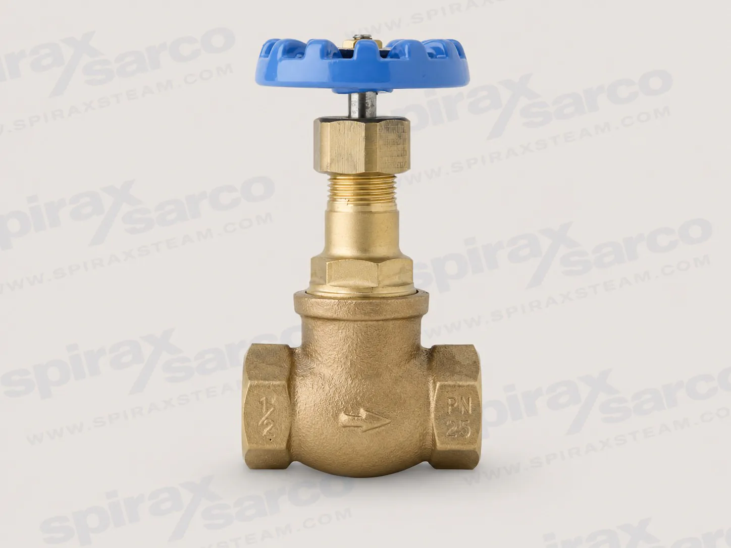
HV3
HV3 Bronze Globe Stop Valve
A PN25 gunmetal-bodied globe stop valve with screwed BSPP connections from ½ to 2 in for isolating compatible steam, water, oil and air services.
The Spirax Sarco HV3 stop valve is a manually operated, bronze-bodied globe valve for positive line isolation in steam, water, oil and air services. It is manufactured to BS 5154 Series A and is supplied with screwed BSPP parallel connections from ½ in to 2 in. The combination of a PN25 body design, a compact threaded installation and replaceable wearing parts makes the HV3 a practical choice where a general-purpose stop valve must be easy to specify, operate and maintain.
Spirax Sarco positions the HV3 primarily for general isolation duties and, in particular, for isolating steam trap sets. That role makes it relevant to many small-bore steam and condensate assemblies where operators need a clear manual shut-off point before inspection or maintenance. The same valve construction is also documented for compatible Group 2 industrial-fluid applications involving water, oil or compressed air. Selection must always confirm the actual fluid, pressure, temperature, connection and material compatibility rather than relying on nominal pipe size alone.
The globe-pattern flow path uses a handwheel-driven stem to move the valve member onto or away from its seat. This gives the operator a direct, familiar manual action and a visible indication of stem movement. The HV3 is intended as a stop valve: its primary job is to isolate the line so that downstream equipment can be operated or serviced under the site’s approved procedures. It should be opened and closed gradually to avoid system shock, and the surrounding system must provide any overpressure or overtemperature protection required by the application.
The design combines a gunmetal body and bonnet with an AISI 431 stainless-steel valve and seat. PTFE gland packing seals around the stem, while an aluminium handwheel provides manual operation. The stem material varies with size: ½–1 in valves use austenitic stainless steel to BS 970 303 S31, while 1¼–2 in valves use gunmetal to BS 1400 LG2. These details matter when checking corrosion resistance, temperature exposure and maintenance requirements for a particular service.
Routine service is supported by two defined spare groups: the valve-and-seat assembly and a packet of three gland-packing rings. This allows common sealing and shut-off components to be renewed without replacing the complete valve. The HV3 is identified by its blue handwheel; the official instructions specifically warn that its spares are model-specific. Always order against the HV3 description and valve size rather than matching parts by appearance.
The HV3 has maximum body design conditions of PN25. Its maximum allowable and maximum operating pressure are both 25 bar g at 170 °C. Its maximum allowable and maximum operating temperature are both 260 °C at 10.5 bar g, while the minimum allowable and operating temperature is -10 °C. The documented maximum cold hydraulic test pressure is 38 bar g.
These figures describe a pressure/temperature relationship, not independent limits that can be combined without reference to the envelope. At elevated temperature the permissible pressure reduces, and the shaded prohibited region on the official curve must not be entered. Confirm the actual design point against the curve and include a suitable safety device if failure or an upstream condition could expose the valve to pressure or temperature above its allowable limits.
All documented HV3 sizes use screwed BSPP parallel connections. The available nominal pipe sizes are ½, ¾, 1, 1¼, 1½ and 2 in. Kv rises with valve size, from 1.3 at ½ in to 28 at 2 in. The complete sequence is 1.3, 1.6, 4.2, 13.8, 19.7 and 28. Those coefficients help an engineer compare the valve’s hydraulic capacity with the required flow, but they do not replace a system pressure-drop calculation or the requirement to remain inside the pressure/temperature envelope.
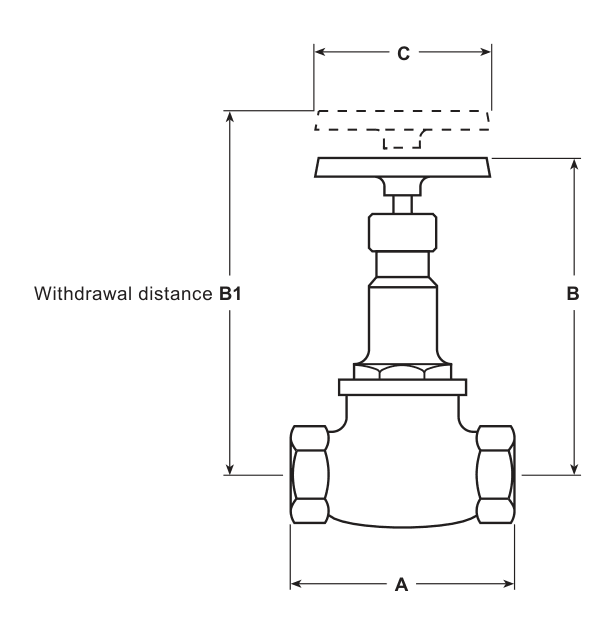
Physical space also changes with size. The technical information provides face-to-face dimension A, closed height B, withdrawal distance B1, handwheel width C and approximate mass for every connection size. Withdrawal distance is particularly important where the bonnet or internals must be removed in place. Allow operating and maintenance clearance around the handwheel and bonnet before finalising the pipe layout.
A common HV3 duty is manual isolation around a steam trap set. Installed at the appropriate locations and used under an approved isolation procedure, the valves allow the trap station to be separated from the live system before inspection or maintenance. If the broader project is still at the trap-selection stage, review the available steam trap technologies and applications before fixing the station arrangement.
The valve can also serve compatible water, oil and compressed-air lines within its documented material and operating limits. Because the instructions define the intended PED service as Group 2 fluids, applications outside that scope need specific engineering review. The HV3 should not be assumed suitable for hazardous media simply because pressure and temperature appear acceptable. Fluid classification, material compatibility, local regulations and the consequences of leakage must all be checked.
Within a complete station, upstream debris can damage the seating surfaces or operating mechanism. The installation manual therefore recommends a pipeline strainer upstream of the valve where abrasive particles may be present. Suitable options can be reviewed in the strainers and filters range. For projects comparing different shut-off principles, body materials or emission-control requirements, review the wider isolation valve range rather than assuming that one globe-valve design fits every service.
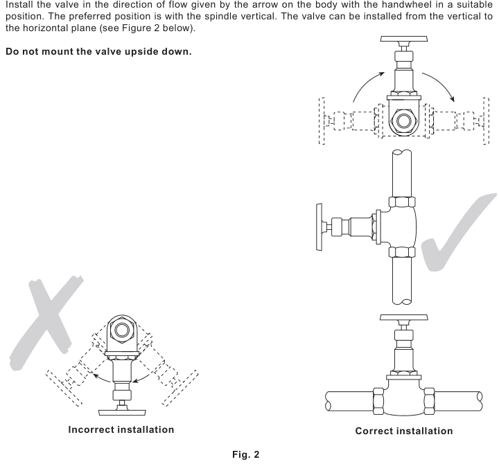
Install the valve so that flow follows the arrow cast on the body. The preferred arrangement has the spindle vertical. Installation between the vertical and horizontal plane is permitted, but the valve must not be mounted upside down with the handwheel below the body. Before installation, confirm size, pressure rating, construction materials and end connections; remove connection protection; clean out storage debris; and maintain pipeline cleanliness during assembly.
Wherever practical, leave enough space for safe operation and maintenance. After installation or maintenance, verify that the system is fully functional and test any alarms or protective devices. To open the valve fully, turn the handwheel anticlockwise until the stem reaches its maximum raised position, then turn the handwheel ⅛ to ¼ turn clockwise to remove backlash. This prevents an operator from trying to force a valve that is already fully open and damaging the stem or related components.
Regular scheduled inspection is especially important for isolation valves that are operated only occasionally. Before work, isolate the line, vent pressure safely to atmosphere and allow temperature to normalise. A zero pressure-gauge indication is not proof that the system is depressurised; use the site’s locking, labelling and permit-to-work controls, and consider double isolation with bleed where the risk assessment requires it.
The external surface may reach 260 °C at the upper operating limit, and the valve is not necessarily self-draining. Residual hot fluid, frost exposure and the previous contents of the pipeline must therefore be included in the maintenance plan. PTFE packing that approaches 260 °C can emit toxic fumes, and removed PTFE packing must be handled and disposed of by the approved method described in the installation instructions. Use the specified tightening torque for the valve size and component, then restore pressure slowly and check for leakage.
Before requesting an Spirax Sarco HV3, confirm the following information:
The order description should state the quantity, HV3 stop valve and BSP parallel connection size. If the service point is close to a published limit or uses a fluid not clearly covered by the documentation, provide the complete operating conditions for engineering review rather than selecting from pressure class alone. This keeps the Spirax Sarco HV3 specification aligned with the real duty and gives the installer the information needed to plan a safe, maintainable isolation point.
The HV3 is a bronze-bodied globe valve for steam, water, oil or air applications, manufactured to BS 5154 Series A.
½ in, ¾ in, 1 in, 1¼ in, 1½ in and 2 in screwed BSPP (parallel).
| Size | ½ in | ¾ in | 1 in | 1¼ in | 1½ in | 2 in |
|---|---|---|---|---|---|---|
| Kv | 1.3 | 1.6 | 4.2 | 13.8 | 19.7 | 28 |
For conversion: Cv (UK) = Kv × 0.963; Cv (US) = Kv × 1.156.
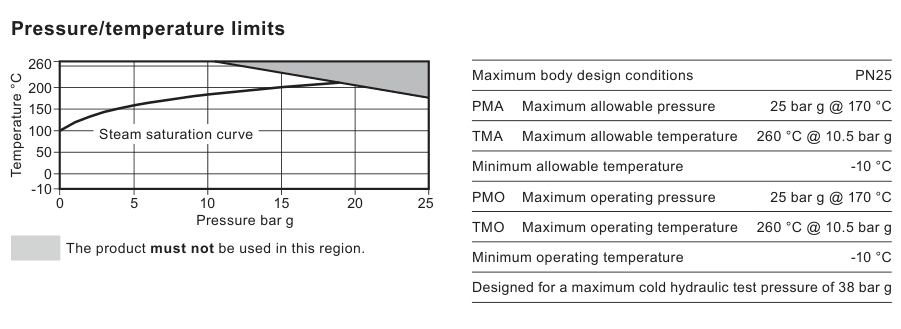
| Maximum body design conditions | PN25 |
|---|---|
| PMA — maximum allowable pressure | 25 bar g at 170 °C |
| TMA — maximum allowable temperature | 260 °C at 10.5 bar g |
| Minimum allowable temperature | -10 °C |
| PMO — maximum operating pressure | 25 bar g at 170 °C |
| TMO — maximum operating temperature | 260 °C at 10.5 bar g |
| Minimum operating temperature | -10 °C |
| Maximum cold hydraulic test pressure | 38 bar g |
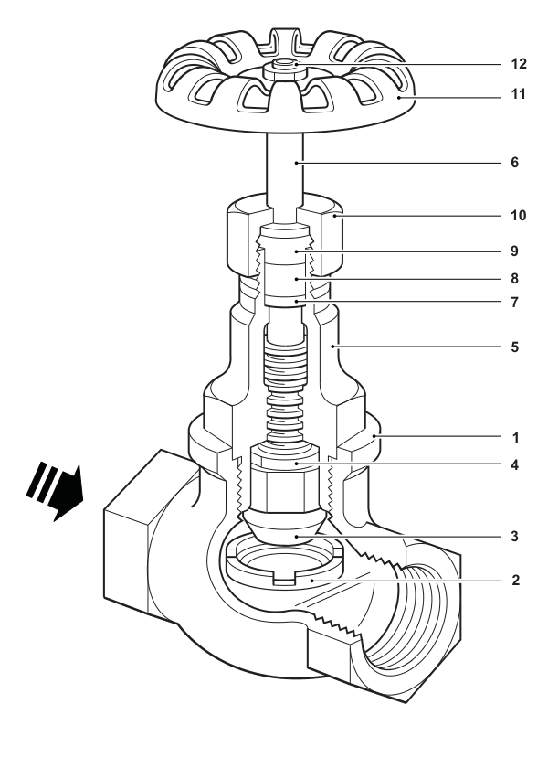
| No. | Part | Material | Standard |
|---|---|---|---|
| 1 | Body | Gunmetal | BS 1400 LG2 |
| 2 | Valve seat | Stainless steel | AISI 431 |
| 3 | Valve | Stainless steel | AISI 431 |
| 4 | Lock-nut | Gunmetal | BS 1400 LG2 |
| 5 | Bonnet | Gunmetal | BS 1400 LG2 |
| 6 | Stem, ½–1 in | Austenitic stainless steel | BS 970 303 S31 |
| 6 | Stem, 1¼–2 in | Gunmetal | BS 1400 LG2 |
| 7 | Washer | Gunmetal | BS 1400 LG2 |
| 8 | Gland packing | PTFE | — |
| 9 | Gland | Gunmetal | BS 1400 LG2 |
| 10 | Packing nut | Gunmetal | BS 1400 LG2 |
| 11 | Handwheel | Aluminium | DIN 1725 GK-A1 Si 1 |
| 12 | Handwheel nut | Brass | DIN 17660 MS63 |
| Size | A (mm) | B (mm) | B1 (mm) | C (mm) | Weight (kg) |
|---|---|---|---|---|---|
| ½ in | 67 | 102 | 110 | 60 | 0.60 |
| ¾ in | 80 | 110 | 125 | 60 | 0.86 |
| 1 in | 95 | 130 | 146 | 80 | 1.30 |
| 1¼ in | 112 | 144 | 160 | 100 | 2.08 |
| 1½ in | 132 | 144 | 160 | 100 | 2.86 |
| 2 in | 160 | 174 | 203 | 120 | 4.65 |
Install the valve in the direction of flow shown by the arrow on the body. The valve may be installed in any plane except with the handwheel below the valve body. For full safety, installation and maintenance requirements, follow IM-P060-04.
The product is recyclable. No ecological hazard is anticipated from disposal provided due care is taken. PTFE gland packing is subject to the specific handling and disposal requirements in the installation instructions.
State the quantity, HV3 stop valve and BSP parallel connection size. Example: one HV3 stop valve with 1½ in BSP parallel connections.
| Spare | Item numbers |
|---|---|
| Valve and seat assembly | 2, 3 |
| Gland packing, packet of three | 8 |
Model-specific spare warning: these spares apply only to the HV3, identified by its blue handwheel. They are not interchangeable with parts for the green-handwheel HV1 or red-handwheel HV2.
Safe operation can be guaranteed only when the product is properly installed, commissioned, used and maintained by qualified personnel in accordance with the operating instructions. Follow the general requirements for pipeline and plant construction and use the correct tools and safety equipment.
Check the nameplate, technical information and these instructions to confirm that the valve is suitable for the intended application. The HV3 is specifically designed for steam, compressed air, water and other industrial fluids in Group 2 of the applicable Pressure Equipment Directive classification. The manual records DN15–DN40 as SEP for Group 2 gases and liquids; DN50 is Category 1 for Group 2 gases and SEP for Group 2 liquids. Products classified as SEP do not carry the Directive marking.
Isolate pressure and vent it safely to atmosphere before work. Consider double isolation with bleed, together with locking or labelling closed valves. Do not assume that the system is depressurised because a pressure gauge reads zero. Allow sufficient time for temperature to normalise and protect against burns.
PTFE warning: gland packing exposed to a temperature approaching 260 °C or above can release toxic fumes. Enforce a no-smoking rule wherever PTFE is stored, handled or processed; tobacco contaminated by PTFE particles can cause polymer-fume fever when burned.
The valve is recyclable and presents no anticipated ecological hazard when handled with due care. Do not incinerate removed PTFE packing. Keep PTFE waste separate and use an approved disposal method. When returning a product, provide written details of contamination, residues or mechanical damage that could create a health, safety or environmental risk, including relevant safety data sheets.
The HV3 is a bronze-bodied globe stop valve for steam, water, oil or air applications to BS 5154 Series A. Available connections are ½, ¾, 1, 1¼, 1½ and 2 in screwed BSPP parallel, corresponding to nominal sizes DN15, DN20, DN25, DN32, DN40 and DN50. Refer to Technical Information Sheet TI-P060-01 for full materials, dimensions, weights and Kv values.
| Maximum body design conditions | PN25 |
|---|---|
| Maximum allowable pressure | 25 bar g at 170 °C (362.5 psi g at 338 °F) |
| Maximum allowable temperature | 260 °C at 10.5 bar g (500 °F at 152 psi g) |
| Minimum allowable temperature | -10 °C (14 °F) |
| Maximum operating pressure | 25 bar g at 170 °C (362.5 psi g at 338 °F) |
| Maximum operating temperature | 260 °C at 10.5 bar g (500 °F at 152 psi g) |
| Minimum operating temperature | -10 °C (14 °F) |
| Maximum cold hydraulic test pressure | 38 bar g (551 psi g) |
The valve must not be used in the prohibited region shown on the pressure/temperature curve in TI-P060-01.
Before installation: observe all safety information above.
After installation or maintenance, confirm that the complete system is functional. Test all associated alarms and protective devices before returning the equipment to normal service.
The HV3 is operated manually by its handwheel. To open fully, turn the handwheel anticlockwise until the stem reaches its highest position. Then turn the handwheel ⅛ to ¼ turn clockwise to remove backlash. This prevents an operator from trying to force open a valve that is already fully open and damaging the stem or other components.
Regular maintenance is the most effective way to support continued operation. Schedule inspections, especially where the valve is operated only occasionally. Before every maintenance task, isolate the valve and allow pressure and temperature to normalise.
| Item | Part | Size | Spanner size | N·m | lbf·ft |
|---|---|---|---|---|---|
| 2 | Seat | ½ in | — | 30 | 22 |
| 2 | Seat | ¾ in | — | 40 | 29 |
| 2 | Seat | 1 in | — | 45 | 32 |
| 2 | Seat | 1¼ in | — | 50 | 36 |
| 2 | Seat | 1½ in | — | 100 | 72 |
| 2 | Seat | 2 in | — | 150 | 107 |
| 5 | Bonnet | ½ in | 25.5 mm A/F | 100 | 72 |
| 5 | Bonnet | ¾ in | 30.5 mm A/F | 150 | 107 |
| 5 | Bonnet | 1 in | 37.0 mm A/F | 175 | 125 |
| 5 | Bonnet | 1¼ in | 42.0 mm A/F | 200 | 143 |
| 5 | Bonnet | 1½ in | 47.0 mm A/F | 250 | 179 |
| 5 | Bonnet | 2 in | 55.5 mm A/F | 380 | 272 |
| 10 | Packing nut | ½ in | 25.5 mm A/F | 20 | 14 |
| 10 | Packing nut | ¾ in | 25.5 mm A/F | 20 | 14 |
| 10 | Packing nut | 1 in | 25.5 mm A/F | 25 | 18 |
| 10 | Packing nut | 1¼ in | 30.5 mm A/F | 40 | 29 |
| 10 | Packing nut | 1½ in | 30.5 mm A/F | 40 | 29 |
| 10 | Packing nut | 2 in | 34.0 mm A/F | 45 | 32 |
| Available spare | Item numbers |
|---|---|
| Valve and seat assembly | 2, 3 |
| Gland packing, packet of three | 8 |
Important: these spares apply only to the HV3, identified by its blue handwheel. They are not interchangeable with the green-handwheel HV1 or red-handwheel HV2. Order by the available-spares description and state the HV3 valve size.
HV3 stop valves are often chosen as part of a practical shut-off arrangement that also depends on leakage expectations, indication and the wider valve strategy around the line.
Return to the wider isolation valve range when you need to compare HV3 stop valves with ball valves and bellows sealed shut-off families.
Use bellows sealed stop valves when external leakage control and lower-emission shut-off matter more than a general-purpose stop valve format.
Review gauges when the isolation point also needs clear operating indication for commissioning, troubleshooting or shutdown procedures.