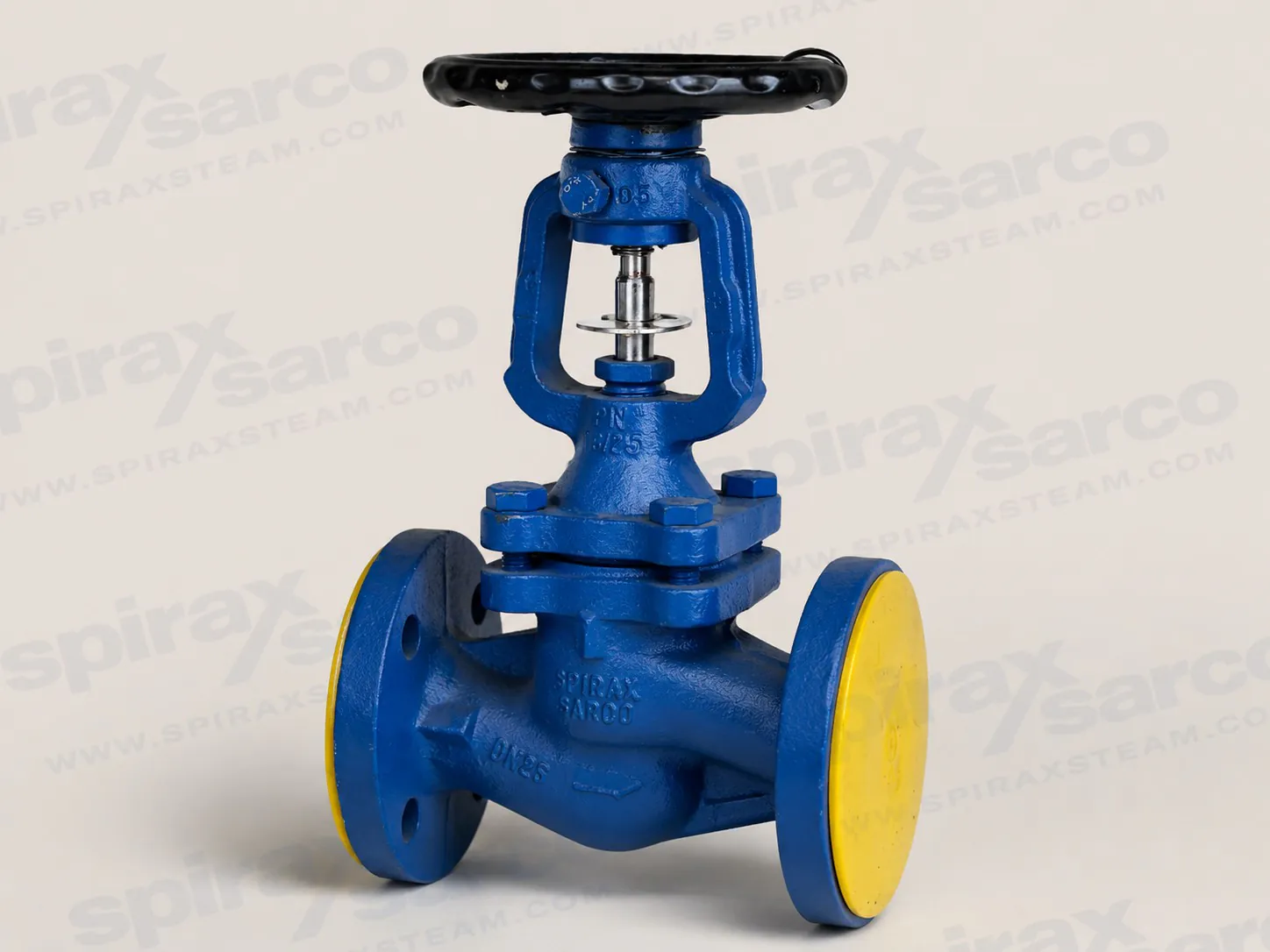
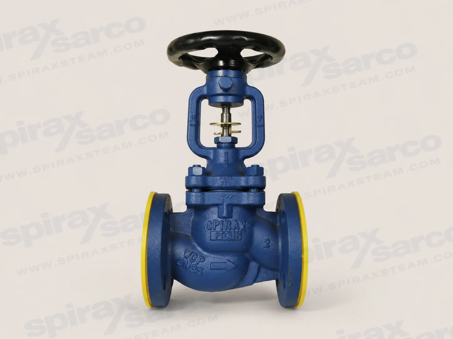
BSA1T bellows sealed stop valve
The Spirax Sarco BSA1T is a cast iron bellows sealed stop valve for manual isolation and limited throttling in steam, condensate, water, gas and compatible industrial fluid systems. Its standard throttling plug and locking device give the operator a controlled way to hold a repeatable position, while the twin-ply bellows keeps the stem sealing arrangement separated from the process medium. The result is a practical isolation valve for plant areas where external stem leakage, maintenance access and dependable shut-off all matter.
BSA1T is the cast iron, 16 bar branch of the BSA/BSAT range. The documented range includes DN15 to DN200 sizes, with flange and connection options shown in the technical information. This page covers BSA1T only. The ductile iron BSA2T and carbon steel BSA3T are different products with different pressure and material boundaries, so their specifications should not be substituted for a BSA1T selection.
Why the bellows sealed construction matters
A conventional packed valve relies on a stem gland that can need adjustment as packing settles or wears. The Spirax Sarco BSA1T instead uses a welded twin-ply bellows as the primary stem seal. When the valve is correctly selected and installed, the bellows arrangement reduces the normal path for stem leakage and supports a cleaner, safer isolation point. A bonnet seal and the handwheel operating mechanism complete the pressure boundary; they do not turn the valve into a maintenance-free component, so inspection and correct operating practice remain essential.
The valve is intended for duties where the line must be isolated repeatedly or remain closed for a maintenance period. Its manual handwheel provides direct feedback, and the locking device can help prevent an unintended change of position after commissioning. The design is especially useful on steam distribution, condensate return, hot-water circuits and process branches where a compact, robust stop valve is preferred over an actuated control valve.
Throttling plug and operating boundary
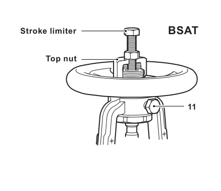
The "T" configuration identifies the throttling-plug version. BSA1T can therefore support limited manual throttling as well as shut-off, but it is not a substitute for a control valve. Throttling creates pressure drop, noise and wear; the technical data limits the differential pressure for this duty to 2.0 bar for DN15-DN80, 1.5 bar for DN100-DN125, 1.0 bar for DN150 and 0.8 bar for DN200-DN250. Only the DN15-DN200 range is relevant to BSA1T. Use the published Kv values and the actual system flow to check the operating point before ordering.
The flat-disc BSA range is intended for a different operating emphasis. If a project needs the throttling plug and locking device described above, specify BSA1T explicitly rather than a similarly named BSA model. If continuous automatic regulation, fast cycling or a tightly controlled set point is required, review a dedicated control valve instead.
Material, pressure and service selection
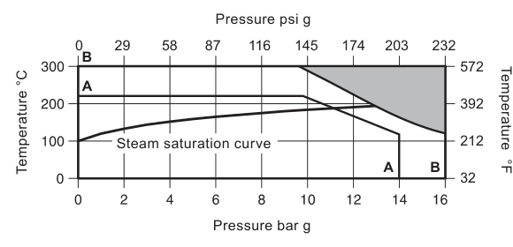
The BSA1T body is cast iron and its documented design pressure is 16 bar. The applicable pressure-temperature envelope, connection standard and size must be checked together; the headline pressure is not a permission to combine every size, flange and temperature without verification. The valve is documented for steam, compressed air, water, condensate and compatible liquids or gases. Chemical compatibility, solids content and temperature cycling still belong in the project review.
For steam isolation, the Spirax Sarco BSA1T bellows sealed stem helps reduce external leakage risk around hot equipment. In condensate and water systems, confirm that the selected connection and pressure class match the pipework and that the valve orientation permits safe drainage where required. Where solids could damage the seat, review suitable upstream strainers and filters. For gas or process-fluid service, check the medium against body, seat and gasket materials and confirm the required shut-off class with the order.
Sizing and ordering checks
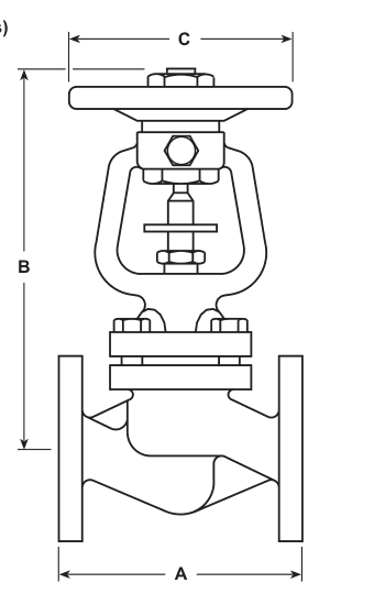
Spirax Sarco BSA1T selection starts with the medium, normal and maximum pressure, operating temperature, required flow and the intended function. Select DN15, DN20, DN25, DN32, DN40, DN50, DN65, DN80, DN100, DN125, DN150 or DN200 only after checking the available connection in the technical table. The general Kv values for the BSA/BSAT range are 4, 7, 12, 19, 30, 47, 77, 120, 193, 288, 410 and 725 for DN15 through DN200 respectively. These are reference flow coefficients, not a guarantee that every system will achieve the desired flow.
- Confirm BSA1T, not BSA1 or another BSA/BSAT model, on the purchase specification.
- Confirm nominal size, flange or pipe connection, pressure class and flow direction.
- Check pressure, temperature and material compatibility for the complete duty cycle.
- State any inspection or test-report requirement when ordering. BSA1T is documented as available with a manufacturer's Typical Test Report.
- If throttling is required, verify the maximum differential pressure and Kv at the intended handwheel position.
The valve complies with the applicable European Pressure Equipment Directive requirements when the documented connection conditions are met. Local regulations can restrict use below the quoted conditions, and all certification or inspection requirements must be stated at order placement.
For broader comparison, the bellows sealed stop valve range provides the correct category context. The BSA1T page remains limited to this cast iron throttling-plug model and does not include the specifications of adjacent products.