
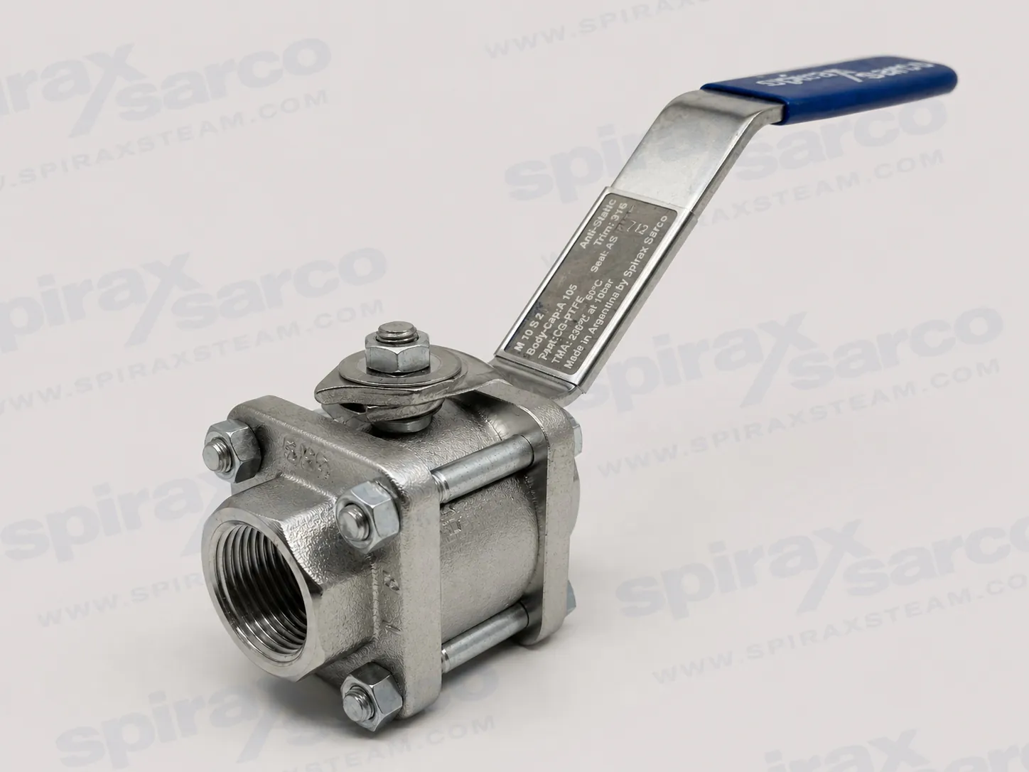
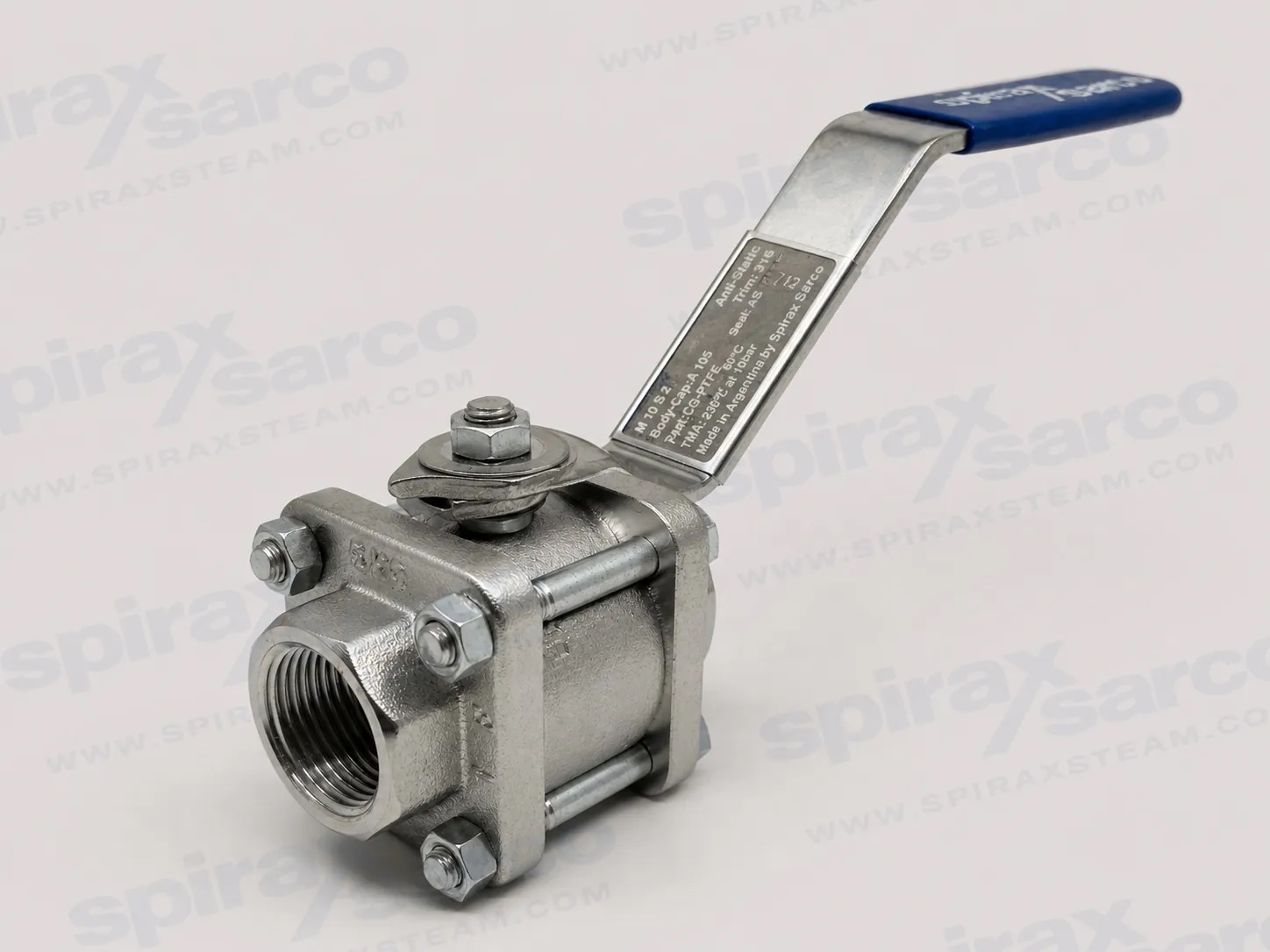
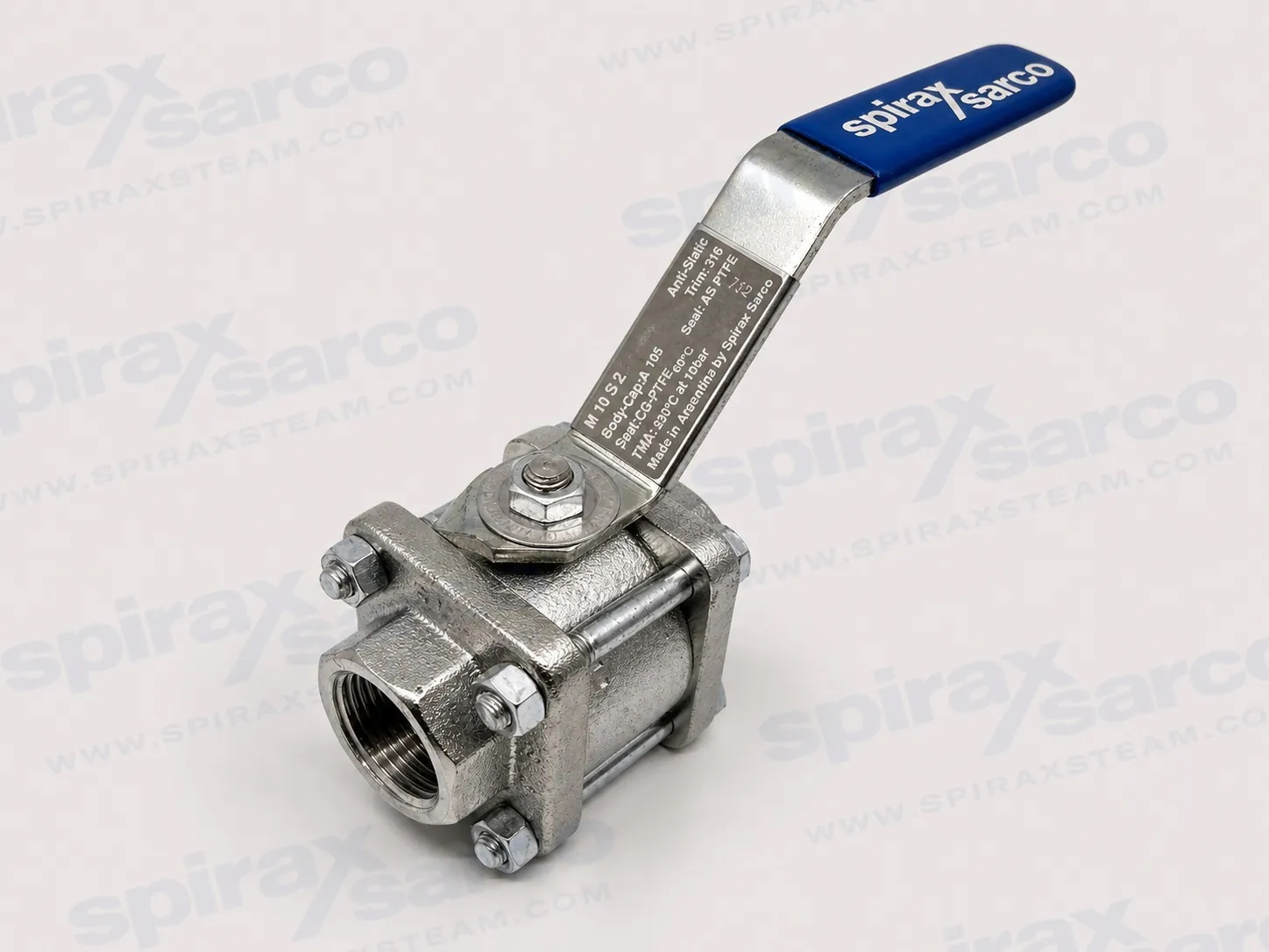
M10S three-piece ball valve
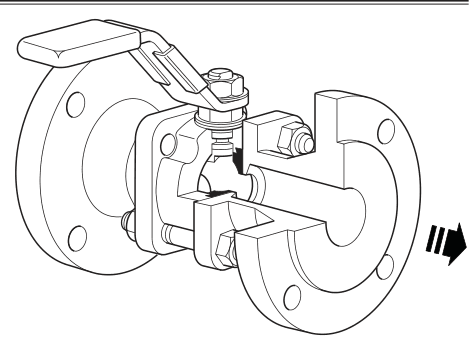
The Spirax Sarco M10S is a three-piece ball valve for positive isolation of steam and other industrial fluids. It is intended for on/off duty, not modulating control. Screwed and welded versions can be serviced without removing the valve from the pipeline, which helps limit disruption where routine seat or stem-seal work is required.
The range is available with full-bore or reduced-bore ports and with screwed, butt-weld, socket-weld and flanged connections. Select the ordered configuration against the applicable connection standard and the official pressure-temperature limits; flange standard and fluid service can impose lower operating limits than the body design condition.
For related isolation equipment, see the Ball valves category. The technical data below is based on Spirax Sarco TI-P133-06, CMGT Issue 22.
Spirax Sarco M10S product scope and connections
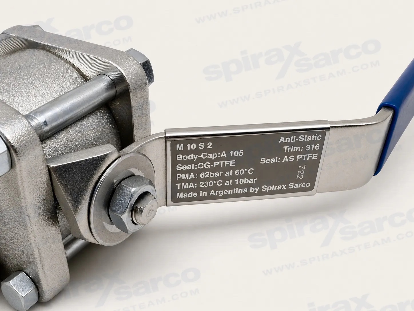
The M10S has a three-piece body, PDR 0.8 carbon/graphite-reinforced PTFE seats, and AISI 316 ball and stem components. It is available in full-bore and reduced-bore versions. Leakage testing is to ISO 5208 Rate A / EN 12266-1 Rate A, and the anti-static device complies with ISO 7121 and BS 5351.
The product is documented against the EU Pressure Equipment Directive and UK Pressure Equipment (Safety) Regulations, and is designed according to ASME B16.34, ASME B16.10 for applicable ASME flanged versions, and EN 558. EN 10204 2.2 and 3.1 certification is available when specified at order placement.
Port configuration | Nominal size | Flanged size | Documented connections |
|---|---|---|---|
Full bore | 1/4 in to 2 in | DN15 to DN50 | BSP, BSPT, NPT, BW Sch40/40S, SW, ASME Class 150/300 and EN 1092 PN40 as applicable |
Reduced bore | 1/2 in to 2 1/2 in | DN15 to DN65 | BSP, BSPT, NPT, BW Sch40/40S, SW, ASME Class 150/300 and EN 1092 PN40 as applicable |
M10S operating limits
Body design condition | PN100 |
|---|---|
Maximum allowable pressure (PMA) | 100 bar g at 60 C |
Maximum allowable temperature (TMA) | 260 C at 0 bar g |
Maximum operating pressure, saturated steam (PMO) | 17.5 bar g |
Maximum operating temperature (TMO) | 260 C at 0 bar g |
Minimum operating temperature | -29 C |
Maximum cold hydraulic test pressure | 150 bar g |
Gas-service restriction | 40 bar g maximum operating pressure |
Operating pressure is limited by the applicable pressure-temperature envelope and may be further restricted by the flange standard. Use the selected connection, port and service medium when confirming the final duty.
Selected construction materials
Part | Material |
|---|---|
Ball | AISI 316 stainless steel |
Stem | AISI 316 stainless steel |
Seat | Carbon/graphite-reinforced PTFE, PDR 0.8 |
Stem seal | Reinforced PTFE, anti-static |
Spring washers | AISI 301 stainless steel |
Name plates | AISI 430 stainless steel |
Flow and operating data
Port | 1/4 in | 3/8 in | 1/2 in | 3/4 in | 1 in | 1 1/4 in | 1 1/2 in | 2 in | 2 1/2 in |
|---|---|---|---|---|---|---|---|---|---|
Reduced-bore Kv | 2.5 | 6.8 | 6 | 10 | 27 | 49 | 70 | 103 | 168 |
Full-bore Kv | 2.5 | 6.8 | 17 | 36 | 58 | 89 | 153 | 205 | Not listed |
Reduced-bore operating torque, Nm | 2 | 2 | 2 | 3.5 | 13 | 21 | 30 | 40 | 45 |
Full-bore operating torque, Nm | Not listed | Not listed | 3.5 | 13 | 21 | 30 | 40 | 45 | Not listed |
For conversion, Cv (UK) = Kv x 0.963 and Cv (US) = Kv x 1.156. The published torque values apply to frequent operation at a 100 bar maximum differential pressure; torque can increase when a valve remains in a fixed position for a long period.
M10S installation, options and service
Confirm size, pressure rating, construction materials and end connection against the actual duty before installation. Avoid pipe misalignment, fit upstream strainers and filters where abrasive particles could damage the seats, and allow access for operation and maintenance. In steam service, fit a trapped drain pocket upstream and open the valve slowly to reduce waterhammer risk.
Only socket-weld and butt-weld connection versions may be welded. They must be dismantled before welding, with each end welded separately and the valve reassembled only after the ends have cooled. Do not weld threaded or flanged carbon-steel versions.
Option or service item | Documented provision |
|---|---|
Optional extras | Self-venting ball, 50 mm or 100 mm extended stems, lockable handle and fully degreased preparation by request |
Available spare parts | Seat and stem seal set |