
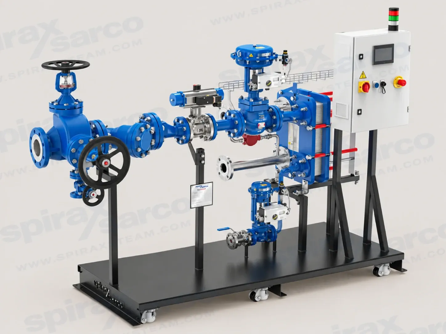
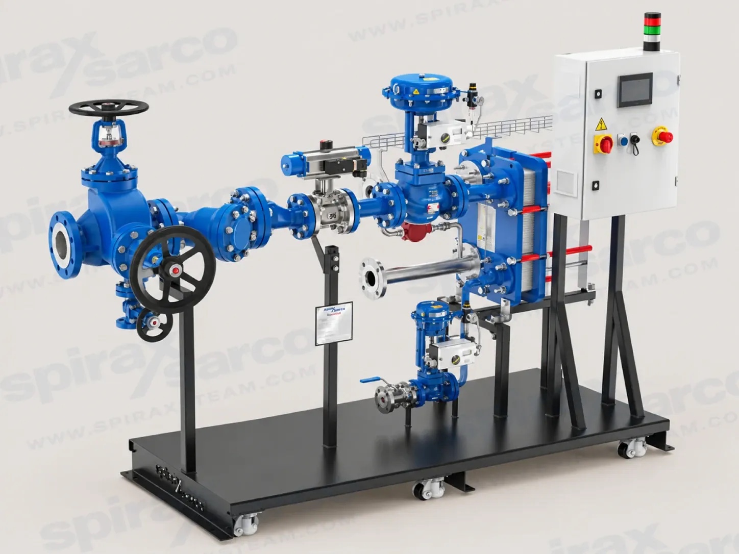
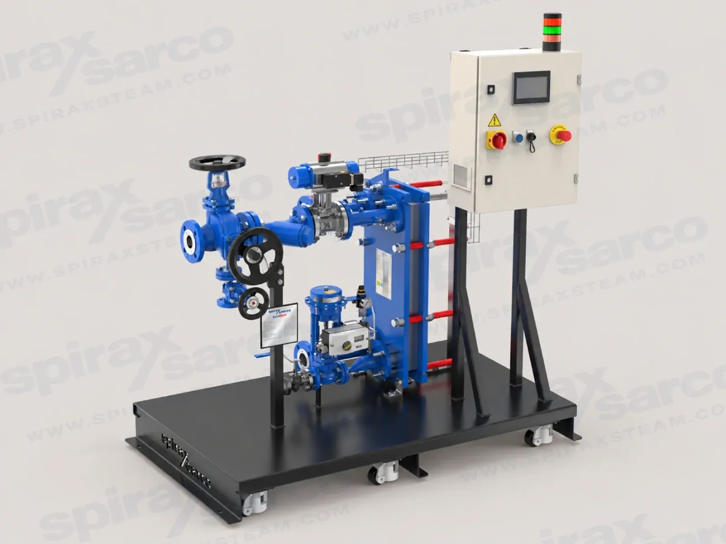
EasiHeat as a packaged heat exchanger system
Spirax Sarco EasiHeat is a compact, packaged steam-to-water heat exchanger system for projects that need controlled low-temperature hot water without assembling a complete heating package from individual components. The system is designed around the required heat load and is supplied as a configured, assembled and pressure-tested package. It combines the steam-side control arrangement, plate heat exchanger, condensate removal solution, sensors, controller, pipework and support frame into one coordinated unit.
The EasiHeat range covers approximately 70 kW to 3.45 MW of heating duty, subject to the selected heat exchanger, control arrangement and application conditions. That range makes it suitable for building services as well as industrial process water. The final package is engineered to the duty rather than selected only by a nominal model name, so the water temperatures, flow conditions, steam supply, condensate return and required safeguards must be confirmed before quotation.
Choose the application before the equipment
EasiHeat applications fall into three connected but distinct duties. HTG systems heat water in a closed circuit for space heating and similar building services. They are suited to comparatively stable load conditions, where the priority is dependable low-temperature hot water, controlled steam use and a package that can be commissioned within a plantroom. DHW systems serve open-circuit domestic hot water, including potable-water duties such as showers, washrooms and kitchens. Process hot water systems can serve open or closed circuits where the load changes significantly and the outlet temperature must remain controlled as demand moves.
The application boundary matters because the water-side material, condensate arrangement, control response and safety functions are selected around the duty. A DHW enquiry should define the required hot-water temperature, demand profile, hygiene strategy and any potable-water requirements. An HTG enquiry should define the flow and return temperatures, circulation arrangement, design load, weather compensation requirements and the relationship with the building control system. A process enquiry should describe the fluid quality, allowable temperature variation, peak and minimum load, operating schedule and consequences of an interrupted heat supply.
Where demand changes quickly, a steam control or dual-control arrangement can provide the fast temperature response required for accurate set-point control. Where load conditions are stable and energy recovery from the condensate is a stronger priority, condensate control may be appropriate. The correct choice is an engineering decision based on the full system, not a replacement for sizing the heat exchanger.
How the package transfers heat
The main heat exchanger is a gasketed plate heat exchanger selected for the specified duty. Steam condenses on the primary side and transfers energy through the plates to the secondary water circuit. The plate arrangement provides a high heat-transfer area in a compact volume, while the gasketed construction allows the heat-transfer surfaces to be inspected and cleaned when the unit is isolated and made safe. The number of plates, channel arrangement and gasket material are selected for the required duty, so they should not be inferred from the appearance of a demonstration unit.
A steam control system regulates the primary steam flow to respond to the hot-water temperature requirement. A condensate control system manages the condensate side and is designed to sub-cool condensate to approximately 95 °C, recovering more of the available energy within the package for suitable stable-load duties. Dual control combines steam and condensate control to support both rapid temperature response and greater use of the available steam energy. The condensate removal method therefore has a direct relationship with control performance, backpressure and the way the package connects to the site return system.
Every package includes a controller and sensors appropriate to its configuration. The panel provides a colour touch-screen interface for operating parameters and alarms, while a signal tower gives a visible indication of the package status. Where the selected configuration includes the relevant connections, operating data can be transferred to an existing control system and a limited period of operating data can be downloaded through the panel. These functions support commissioning and operation; they do not remove the need for competent design, isolation or maintenance.
What the packaged construction changes
A packaged heat exchanger system moves much of the coordination work from the site to the manufacturer. The heat exchanger, control valves, sensors, condensate equipment, ancillary pipework and control panel are arranged on a compact base frame. The package is delivered assembled and pressure tested, reducing the number of field joints and the amount of site assembly required. This can be valuable where a plantroom has a short shutdown window, limited access or a strong need for repeatable installation quality.
The frame provides a defined base for lifting and positioning, but the complete package must still be handled with suitable equipment. It must be lifted from the base and placed on a flat surface capable of supporting the loaded system. The installation guide requires sufficient clearance around the plate heat exchanger for safe disassembly, and the connecting pipework must be independently supported so that external stress is not transferred into the package.
Pipework and the support framework may be configured in carbon steel or stainless steel options according to the system and regional requirements. HTG water-side pipework is specified as carbon steel in the current technical information, while DHW water-side pipework is specified as stainless steel. Steam and condensate pipework are carbon steel in the standard material description, and the steam control valve, condensate pump-trap and condensate control valve use SG iron in the listed arrangement. Final materials remain a project selection item and must be confirmed against the quotation and nameplate.
Control response and energy use
Fast-reacting steam control is intended for fluctuating loads where outlet-temperature accuracy matters. The current technical information describes an indicative static set-point accuracy of ±1 °C, or ±2 °C where electric actuators are used, together with a dynamic response range of +5 °C/-10 °C. These figures describe the documented control performance under the stated conditions; they are not a guarantee for every installation. Water flow stability, sensor location, heat-exchanger sizing, valve authority, steam quality and commissioning all influence the result.
Condensate control is aimed at stable-load duties where reduced response speed is acceptable and energy recovery within the unit is important. Dual control is aimed at temperature-critical duties with rapid load changes, combining a fast primary-side response with condensate sub-cooling. The technical information also describes forward control using return-water temperature or water flow feedback, high-limit protection, integrity testing and optional uninterruptible power supply functions. These features are selected individually; their presence must be checked in the order documentation rather than assumed from the EasiHeat name alone.
Optional communications can connect selected package signals to a building management or plant control system. The available protocol depends on the control-panel configuration and may include BACnet, PROFINET, Modbus, PROFIBUS or EtherNet/IP variants. A project should define which data must be read, which commands may be sent remotely, and how an emergency stop, high-limit trip or loss of utility supply is handled. Remote visibility is an integration feature, not a substitute for local isolation and safe access.
Operating limits that shape selection
For the current EasiHeat technical information, the standard pipework design condition is PN16. The maximum saturated-steam design pressure to the heat exchanger is 9 bar g, the maximum water pressure is 9 bar g, the maximum water temperature is 105 °C, the maximum gasket temperature is 180 °C and the maximum ambient temperature is 50 °C. Higher-pressure design to 12 bar g and higher-temperature gaskets to 200 °C are available on request. These are design limits for the documented configuration and must be compared with the nameplate and project conditions.
The electrical panel is specified for a regional single-phase mains supply, for example 230 Vac at 50-60 Hz. The package has a listed power consumption of 400 W and an IP54 control-panel rating. Electric actuators are supplied from the panel at 24 Vac, while pneumatic actuation requires clean compressed air and the package documentation gives a maximum air supply of 9 bar g. The site design must provide the required isolator, earthing, air quality, cable routes and protection in accordance with national regulations.
Water quality is part of heat-exchanger selection and maintenance. Open systems with continual make-up water are exposed to scaling, and the installation instructions recommend assessing the local water quality. The documented guidance gives pH 6-8, chlorides below 10 ppm and total hardness below 200 ppm as recommended factors. These values do not replace a site water-treatment assessment. Scaling, corrosion and poor steam quality can reduce heat transfer, affect control stability and increase maintenance demand.
Space, connections and maintainability
The maximum package envelope depends on the selected plate type, package configuration and options. The technical information lists typical maximum dimensions up to 1,980 mm high, 2,600 mm long and 870 mm wide for one configuration. Largest connections listed for the range extend to DN200 on the steam side, DN100 on the water side and DN50 on the condensate side. The installation guide separately lists envelope figures for T6-P, TS6-M, T8-M and T10-M heat-exchanger arrangements. Connections are sized to order, so the largest published connection is not an automatic connection specification for a particular enquiry.
Insulation can reduce heat loss and protect personnel from hot surfaces. It is especially important where electric actuation is used, because the installation guide notes that actuator functionality can be impeded when hot components exceed 50 °C. Maintenance access must include the plate pack, control valves, sensors, filters, condensate equipment and electrical panel. The package should be positioned so that operators can isolate primary steam, condensate and secondary water safely, vent residual pressure, and allow the equipment to cool before work begins.
Ordering information to prepare
To size a Spirax Sarco EasiHeat package, provide the application type, design heat load, minimum and maximum water flow, water inlet and outlet temperatures, steam pressure and temperature, condensate return pressure, available electrical supply and pneumatic-air conditions. Also confirm whether the duty is open or closed circuit, whether the water is potable or process water, and whether the load is stable or rapidly changing.
The quotation should identify the control arrangement, heat-exchanger plate type, valve actuation, high-limit protection, manual isolation, recirculation, flow measurement, frame material, wheels, insulation, control-panel position, communications and any required integrity testing. If the system must report to a BMS, define the required signals and protocol before the panel is configured. If the package will be moved through a restricted doorway or lifted into an existing plantroom, confirm the actual envelope and lifting method rather than relying on a typical dimension.
For maintenance planning, record the selected components and their individual installation instructions with the package documentation. The EasiHeat guide is a system-level document and directs users to the relevant component instructions for valves, actuators, pumps, sensors and control equipment. A safe commissioning sequence includes cleaning the connected pipework, checking the design conditions, confirming water circulation, verifying the air and electrical supplies, testing the control response and confirming that safety devices operate before the system is placed into service.
A practical selection summary
A Spirax Sarco EasiHeat enquiry is strongest when it describes the complete thermal duty rather than only requesting a heat exchanger. DHW, HTG and process hot water have different load patterns and material considerations. Steam control, condensate control and dual control have different priorities for response and energy recovery. The frame, valves, instruments, safety functions, electrical supply and condensate route all affect the final package. Confirming these relationships early gives the design team a realistic basis for sizing, quotation, installation and future maintenance.
EasiHeat is therefore best understood as a configurable packaged system, not a single fixed-size appliance. The published limits, dimensions and options provide the selection framework, while the final nameplate, project documentation and manufacturer-approved configuration define the equipment supplied for a particular duty.
Description
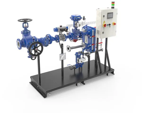
The EasiHeat range provides a compact, turn-key steam-to-water heating solution. Systems are sized for the required heating duty and are supplied fully assembled and pressure tested.
Applications
- HTG: closed-circuit space-heating applications with relatively stable load conditions.
- DHW: open-circuit heated potable-water applications, including showers, washrooms and kitchens.
- Process hot water: open- or closed-circuit heated water applications with high load fluctuations.
Control options
| Option | Function and documented benefit | Suitable application |
|---|---|---|
| Steam control | Fast-reacting temperature control with high set-point accuracy. The documented indicative accuracy is ±1 °C under static loads, or ±2 °C with EL actuators, and +5 °C/-10 °C under dynamic loads. | Fluctuating loads where temperature-control accuracy is important. |
| Condensate control | Designed to sub-cool condensate to approximately 95 °C, keeping more of the available steam energy within the unit. | Stable loads where reduced temperature response time is acceptable, such as heating. |
| Dual control | Combines fast-reacting steam control with condensate control and sub-cooling. | Temperature-critical control applications with rapid load changes. |
| Digital insights | Optional remote condition monitoring and performance insight intended to support efficiency, safety and maintenance decisions. | Applications where temperature control, performance monitoring or uninterrupted hot-water supply is important. |
Standard features
| Feature | Documented function |
|---|---|
| Gasketed plate heat exchanger | High efficiency and low volume-to-pressure ratio; plate count and gasket material are selected for the duty. The exchanger is maintainable and has reduced inspection requirements. |
| Control panel | Colour touch screen for operating parameters and alarms, light tower for status indication and optional communications. Seven days of data can be downloaded through USB. |
| Class VI shut-off | Control valves have steam-tight reversible seats. |
| Actuation supply | Pneumatic or electric actuators can be selected for control and isolation valves. |
| Pipework and support frame | Compact frame and baseplate for installation and mobility. Stainless steel grade 304 or carbon steel options and fitted wheels are available according to the package. |
| Insulation | Available on request and selected for the installation to improve energy efficiency and protect personnel. |
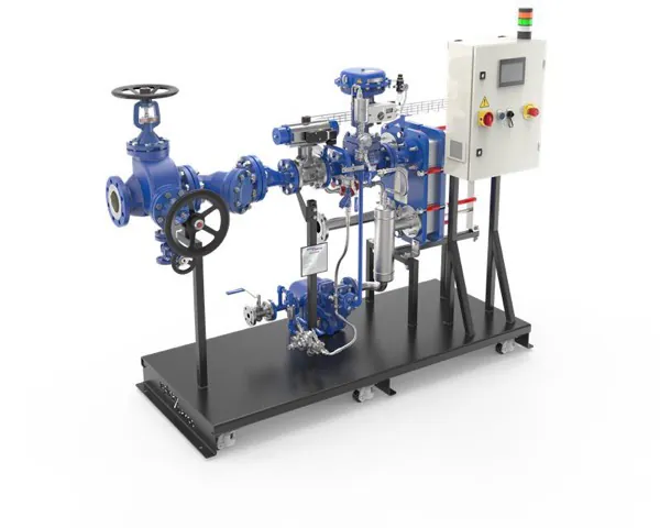
Configurable features
Safety features
| Feature | Purpose | Options |
|---|---|---|
| Fail-safe high limit | Automatically and safely shuts down the system to reduce scalding risk if a fault occurs. | Spirax standard, European EN14597, Italy INAIL or none. |
| Integrity test | Steam-side pressure test using compressed air to verify the heat exchanger gaskets and plates. | Yes or no; requires TA31, PA31 and valve-position feedback. |
| UPS | Provides a safe sequenced shutdown during power loss. | Yes or no. Mandatory for EL actuators where no independent high limit is fitted. |
| Manual steam isolation | Supports local maintenance procedures and processes. | Available on request. |
Advanced control and monitoring
- Forward thermal control can monitor return-water temperature, sequence shutdown and raise an undersized alarm; it requires TA11.
- Forward flow control can monitor return-water flow, sequence shutdown and raise a feedwater or undersized alarm; it requires FA11.
- Communications options include BACnet/IP, PROFINET, Modbus TCP/IP, BACnet MS/TP, PROFIBUS, Modbus RTU, BTL-certified BACnet variants and EtherNet/IP.
- Energy-consumption display, steam-supply failure alarm and condensate-outlet temperature alarm are available with the documented sensors and configuration.
- Optional digital functions include a Legionella risk indicator, gasket-wear detection, scaling detection and energy trending through a cloud platform.
Dimensions and connections
Dimensions are approximate. Piping connections are sized to order and depend on the load and heat exchanger size. Selected options may change the overall dimensions.
| Type | Valve actuation | H (mm) | L (mm) | W (mm) | Steam | Water | Condensate |
|---|---|---|---|---|---|---|---|
| EHDSC | EL or PN | 1980 | 2600 | 850 | DN200 | DN100 | DN50 |
| EHDDC | 950 | DN150 | - | DN25 | |||
| EHHSC | 870 | DN200 | - | DN50 | |||
| EHHDC | 850 | DN150 | - | DN25 | |||
| EHHCC | 870 | DN150 | - | DN25 |
| Type | Valve actuation | H (in) | L (in) | W (in) | Steam | Water | Condensate |
|---|---|---|---|---|---|---|---|
| EHDSC | EL or PN | 77 | 103 | 34 | 8 in | 4 in | 2 in |
| EHDDC | 38 | 6 in | - | 1 in | |||
| EHHSC | 35 | 8 in | - | 2 in | |||
| EHHDC | 34 | 6 in | - | 1 in | |||
| EHHCC | 35 | 6 in | - | 1 in |
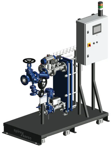
Pressure, temperature, electrical and material limits
| Item | Documented limit or description |
|---|---|
| Pipework design condition | PN16 |
| Maximum saturated steam design pressure to heat exchanger | 9 bar g; 12 bar g high-pressure design available on request. |
| Maximum water pressure | 9 bar g |
| Maximum water temperature | 105 °C |
| Maximum gasket temperature | 180 °C; 200 °C high-temperature gaskets available on request. |
| Maximum ambient temperature | 50 °C |
| Electrical panel supply | Regional single-phase mains supply, for example 230 Vac at 50-60 Hz. |
| Actuator supply | Electric: 24 Vac from the panel. Pneumatic: maximum 9 bar g. |
| Power consumption | 400 W |
| Control panel rating | IP54 |
| Steam and condensate pipework | Carbon steel |
| Steam control valve and condensate pump-trap | SG iron |
| Water-side pipework | HTG: carbon steel. DHW: stainless steel. |
| Condensate control valve | SG iron |
The current technical information supersedes older local sheets where limits differ. Always compare the package nameplate, quotation and site design conditions before operation.
EasiHeat nomenclature
The nomenclature is split into three groups. The example below illustrates how a selected package is described; values are not a universal configuration for every EasiHeat system.
| Position | Selection field | Documented values |
|---|---|---|
| 1 | Application type | EHDSC domestic hot water, steam-side control; EHDDC domestic hot water, dual control; EHHSC heating, steam-side control; EHHCC heating, condensate control; EHHDC heating, dual control. |
| 2 | Steam control valve size | 1 DN32 TS6-M; 2 DN40 TS6-M; 3 DN50 TS6-M; 4 DN65 TS6-M; 5 DN80 T8-M; 6 DN100 T10-M. |
| 3 | Steam control valve Kvs | 0 none, or a Kvs value from the EasiHeat sizing software. |
| 4-5 | Insulation and split range | N/L for none or lagged insulation; 0 for none or a split-range Kvs value. |
| 6-7 | Condensate control valve | 0 = none; 1 = DN15; 2 = DN20; 3 = DN25; 1.1, 2.1 and 3.1 are the corresponding large-inlet variants. Kvs is selected for the valve body. |
| 8-9 | Heat exchanger | Plate count selected for the sized exchanger and channel types LL, LW, MH, MW, HH or HW. |
| 10 | Gasket material | G1 = EPDMP; G2 = Heat-seal; G3 = WRAS EPDMW (UK only); G4 = EPDMP, G5 = Heat-seal or G6 = WRAS EPDMW for 12 bar g design where available. |
| 11-13 | Global variance, actuation and condensate removal | UK, EU, AS/UL, CA, KO, JA, CH, SI or MA variance; PN = pneumatic or EL = electric actuation; N = none, ST = steam trap, PT = pump trap or PTHC = high-capacity pump trap. |
| Position | Selection field | Documented values |
|---|---|---|
| 14-16 | High limit, manual steam isolation and recirculation | High limit N, SIHL, IHL or INAIL; manual isolation N, V1 = ball valve, V2 = BSA or V3 = DBB3; recirculation N or R. |
| 17-21 | Panel, frame, supports, panel location and extras | P1 = ABB PLC, P3 = Siemens PLC or B1 = process panel; SS = stainless steel or CS = painted carbon-steel frame; S = static supports or W = wheels; S = standard or M = mirror panel location; GP = gauge pack and/or AP = air preparation set. |
| 22-32 | Integrity, data, sensors, UPS and communications | Integrity N or T; data 00 or 01-09 gateway; valve feedback N or Y; TA11, TA31, TA41, TA01, PA31 and FA11 sensors N or Y; UPS N or Y; C0 = none, C1 = BACnet/IP, C2 = PROFINET, C3 = Modbus TCP/IP, C4 = BACnet MS/TP, C5 = PROFIBUS, C6 = Modbus RTU, C7/C8 = BTL-certified BACnet or C9 = EtherNet/IP. |
Installation and Maintenance Guide
This system-level document covers the EasiHeat package. Use it with the product-specific instructions supplied for the valves, actuators, pumps, sensors, flowmeter and control equipment fitted to the ordered package.
The package must be installed, commissioned and maintained by competent personnel who have read the complete instructions and the equipment nameplate. Local regulations and the actual supplied configuration take precedence where they impose a more restrictive condition.
1. Safety information
Safe operation can be guaranteed only when the EasiHeat system is correctly installed, commissioned and maintained by a qualified person in accordance with these instructions, the relevant component instructions and applicable pipeline, plant, tool and safety-equipment requirements.
Isolation and residual energy
Before installation or maintenance, isolate the primary steam, condensate and secondary water-return lines. Vent residual pressure to atmospheric level and do not assume that a zero gauge reading proves that the system is depressurised. Lock or label isolating valves where required.
Hot surfaces and scalding
Allow all parts to cool after isolation. Heated water can cause scalding directly or indirectly, so a high-limit device and a suitable risk assessment are required where personnel could be exposed to hot water. Wear suitable protective clothing and eye protection.
Lifting
Lift the complete assembly only from its base with a suitable forklift truck or approved lifting method. Do not lift it by pipework, valves, the heat exchanger, control panel or another component. The customer is responsible for safe lifting, placement and fastening to the floor where required. The package has a high centre of gravity.
Access and environment
Provide adequate lighting, safe access and a guarded working platform when necessary. Assess flammable substances, confined or oxygen-deficient spaces, hazardous gases, hot surfaces, fire hazards, noise, moving machinery and other risks around the installation. Keep sufficient clearance for future maintenance.
Pressure equipment
Check the nameplate and technical information against the intended steam and water service. If a component limit is lower than the system limit, fit suitable protective devices to prevent dangerous overpressure or overtemperature. The installer must account for stresses induced by connected pipework.
Electrical hazard
The control panel contains hazardous voltages. Work on an energised open panel is restricted to suitably qualified and competent personnel. Fit a lockable isolator adjacent to the unit, connect protective bonding correctly and follow national electrical regulations.
Water quality
High-efficiency plate heat exchangers are sensitive to poor water quality. The documented recommended factors are pH 6-8, chlorides below 10 ppm and total hardness below 200 ppm. Confirm the actual site water with a water-treatment specialist to limit scaling and corrosion.
Legionella
Legionella is a risk in hot-water systems. Apply the relevant national guidance and site controls. Available monitoring features can support risk management, but they do not replace the operator's water-hygiene procedures or risk assessment.
Work control
Use suitable tools and consumables, genuine replacement parts, trained personnel, permits to work and warning signs where required. Consider manual-handling risks and use appropriate lifting methods rather than bodily force.
Intended use and pressure-equipment classification
Check the installation instructions, nameplate and technical specifications to confirm that the package is suitable for the intended application, material, pressure, temperature and fluid group. The manual describes EasiHeat DHW and HTG assemblies for Group 2 fluids as Category I, with EasiHeat DHW and HTG using a T10 heat exchanger with 46 or more plates described as Category II. Bespoke units must be checked against the declaration and supplied documentation.
The assembly is designed for steam and water service. Determine the correct installation position and fluid-flow direction, remove protective covers and packaging before installation, and do not expose the unit to external stresses from unsupported or misaligned pipework.
Storage, freezing, disposal and return
- Inspect the package and protective covers for transport damage on receipt. If immediate installation is not possible, protect the heat exchanger from rust, moisture and contamination.
- Store under cover, preferably indoors, above grade, dry and at low humidity. The suggested storage range is 0 °C to 50 °C with relative humidity at 40% or lower. The installation environment should remain above 0 °C and below 40 °C.
- Protect non-self-draining components from freezing. Dispose of PTFE, Viton and electrical components in accordance with the applicable local and national regulations. PTFE must not be incinerated in an unauthorised system.
- When returning a contaminated or damaged product, provide written information about residues, hazards, precautions and relevant safety data sheets.
2. General product information
EasiHeat uses steam to heat low-temperature hot water for HTG, domestic hot water for DHW, or process hot water. Systems can be sized from approximately 70 kW to approximately 3.5 MW and are supplied fully assembled and pressure tested, ready for installation.
The three basic package configurations are steam control, condensate control and dual control. Dual control manages temperature and pressure within the heat exchanger so that more available energy can be transferred to the heated medium. Additional options include high-limit valves, isolation, metering, recirculation, integrity testing, communications and other application-specific safeguards.
| Reference | Core item | Function |
|---|---|---|
| A | Steam plate heat exchanger | Type T6-P, TS6-M, T8-M or T10-M, selected for the duty. |
| B | Steam control valve and positioner | Pneumatically or electrically actuated primary-side control. |
| C | PLC controller and sensors | Control, measurement, alarms and selected communications. |
| D | Condensate removal solution | Trap, pump-trap or condensate control arrangement as ordered. |
| E | Pipeline ancillaries | Ancillary valves and devices selected for the package. |
| F | Lockable isolator | Local electrical isolation and safe maintenance control. |
3. Installation
3.1 Dimensions and insulation
Dimensions are approximate and options can change the overall envelope. Piping connections are sized to order and depend on the load and heat exchanger size. Thermal insulation is recommended to reduce heat loss and protect personnel from contact with hot surfaces. With electric actuation, hot pipework and components must be insulated because actuator function can be impaired above 50 °C.
| Plate type | H (mm) | L (mm) | W (mm) | Steam | Water | Condensate |
|---|---|---|---|---|---|---|
| T6-P | 1995 | 1944 | 850 | DN80 | DN65 | DN15 |
| TS6-M | 1995 | 2488 | 850 | DN125 | DN65 | DN40 |
| T8-M | 1995 | 2488 | 850 | DN150 | DN80 | DN50 |
| T10-M | 1995 | 2932 | 904 | DN200 | DN100 | DN50 |
| Plate type | H (in) | L (in) | W (in) | Steam | Water | Condensate |
|---|---|---|---|---|---|---|
| T6-P | 78.5 | 76.5 | 34 | 3.15 in | 2.5 in | 0.5 in |
| TS6-M | 78.5 | 98.0 | 34 | 5 in | 2.5 in | 1.5 in |
| T8-M | 78.5 | 98.0 | 34 | 6 in | 3.15 in | 2 in |
| T10-M | 78.5 | 115 | 35.5 | 8 in | 4 in | 2 in |
3.2 Steam, condensate and water connections
Supply steam, and compressed air where pneumatic actuation is selected, as dry and clean as possible. Use a suitable line steam trap upstream so that the line is free of condensate when isolated or off-line. Do not connect dual-control or condensate-control discharge into an existing condensate return line where this could cause pressurisation or condensate-induced water hammer.
Keep connected pipework stress free and independently supported. Maintain the steam at the specified design pressure and temperature; never operate above the limit on the plate heat exchanger nameplate. Fit an appropriately sized safety or relief valve where required to protect the hot or cold side. If secondary flow and return isolation can hydraulically lock water in the exchanger, provide suitable relief protection.
Size steam, condensate and water pipework independently to the package connection size. Downstream condensate pipework must account for mixed-phase flow, including flash steam, rather than simply matching the condensate outlet. Where double-block-and-bleed isolation or an automatic pump-trap is fitted, consider drainage points. A control valve is used instead of a steam trap or automatic pump-trap on dual-control and condensate-control systems.
3.3 Positioning and fastening
Place the unit on a completely flat, horizontal surface able to support its full loaded weight. Provide at least one metre of clearance from the plate heat exchanger fixings to allow safe disassembly. Fasten the base where the project requires it, and keep access to the local isolator, control panel, valves and drain points clear.
3.4 Air supply
For pneumatic control, connect clean compressed air up to a maximum of 9 bar g. Use the actuator-specific installation instructions when lifting or working around the control valve.
| Actuator | Control-valve inlet | Actuator supply pressure |
|---|---|---|
| PN9126E | DN15, DN20, DN25 | 3-6 bar g |
| PN9123E | DN32, DN40, DN50 | 5-6 bar g |
| PN9233E | DN65, DN80 | 5-6 bar g |
| PN9320E | DN100 | 2-3 bar g |
3.5 Electrical supply
Carry out electrical wiring and connections in accordance with national regulations. Fit a lockable isolator or switch-disconnector next to the unit. Connect the mains supply to the primary side of the incoming control-panel isolator and connect the main earth terminal. The panel supply is 230 Vac/50 Hz, power consumption is 400 W and maximum current draw is 1.6 A; verify the supplied panel documentation for the actual regional arrangement.
3.6 Signal tower
The three-lamp tower allows the package status to be seen without inspecting the HMI. The positions are fixed, although lamp colours may be changed with the understanding that the result may no longer match BS EN 60204 requirements.
| Position | Colour | Purpose | Meaning |
|---|---|---|---|
| Top | Amber | Emergency stop | Illuminated when the EasiHeat is in an E-stop state. |
| Middle | Green | Operational | Illuminated when the EasiHeat system is running. |
| Bottom | White | Power | Illuminated when the control panel is powered on. |
The tower can be removed carefully to reduce package height during transport through restricted areas. Replace it after positioning and protect the wiring with the supplied black endcap when the tower is removed.
3.7 Electrical specifications and customer connections
| Item | Specification |
|---|---|
| Power supply | 230 Vac/50 Hz |
| Power consumption | 400 W |
| Maximum supply conductor | 16 mm2 |
| Maximum current draw | 1.6 A |
| Panel fan fuse F1 | 0.5 A slow blow |
| PLC/HMI/communications fuse F3 | 3 A quick blow |
| Steam and auxiliary/condensate valve fuse F4/F5 | 5 A slow blow, 5 x 20 mm cartridge |
| 24 Vac supply fuse F6 | 0.5 A slow blow |
Customer connections can include normally open volt-free E-stop alarm and run-to-BMS contacts. Remote terminals can provide external E-stop inputs, remote stop and start requests, remote set-point or outside-temperature compensation, valve position retransmission, hot-water set-point transmission and outlet-temperature retransmission. Both external E-stop connections are required for the external E-stop function.
4. Commissioning
Commissioning support from a competent service engineer is recommended. Complete the installation checks before applying steam and follow the component instructions for the fitted valves, actuators, flowmeter, pump and safety devices.
4.1 Pre-commissioning inspection
- Check all bolts and fasteners. Fit the TA01 return-loop sensor before adding make-up water if that option is installed.
- Remove dirt and construction debris from connected pipework. Clean upstream filters on regulating valves.
- Confirm that manual primary-steam, condensate and secondary-water isolating valves are closed before starting the sequence.
- Verify that steam and water design conditions do not exceed the package ratings, and that the steam line is pressurised, drained and vented correctly.
- Double-check every steam, condensate and water connection and verify the pneumatic filter/regulator supply where applicable.
4.2 Commissioning procedure
- Perform a dry valve-stroke check. Use the relevant electric or pneumatic control-valve instruction for the actuator.
- Open the secondary cold-side isolating valves downstream of EasiHeat.
- Start the main secondary circulating pumps if fitted and confirm water circulation through the package.
- Switch on the main control-panel power and turn the panel isolation switch to ON.
- Commission the flowmeter if fitted. If a pneumatic isolation valve is fitted, confirm the panel wiring and air supply, start the system from the HMI and check that the valve opens in approximately 10-15 seconds. It must not take less than 5 seconds or more than 60 seconds to open; adjust the flow restrictor only as described in the manual and lock the final setting.
- Open all condensate drain valves, slowly open the steam inlet valve and monitor process temperature. Do not adjust high-limit opening time below 5 seconds; changes to that setting are restricted to a suitably qualified service engineer.
4.3 Flowmeter commissioning
Select the LIQU operating mode for EasiHeat packages. Set the internal pipe diameter so the flowmeter can calculate volumetric flow. The documented internal diameters are DN50: 52.5 mm, DN80: 77.9 mm and DN100: 102.2 mm, measured in accordance with BS1600:1991.
- Enter the device menu and select the operating mode.
- Choose LIQU and confirm so that the device reboots.
- Open the diameter setting, enter the internal pipe diameter in millimetres and confirm the value.
- Exit the menu and verify that the display shows the expected flow unit.
For optimum measuring accuracy, orient the sensor so flow reaches the larger key surface and do not pass the sensor beyond its end stop. Follow the flowmeter instruction if the sensor is removed.
4.4 HMI commissioning
This stage may have been completed at the factory. After completing the preceding checks, use the HMI to tap the welcome screen, select the language, choose engineering units, set the date and time, enter the product nomenclature from the documentation pack, select local/remote/communications controls, enter the operating conditions and confirm completion with the green tick.
4.5 Start-up procedure
- Confirm that steam is available at the required pressure, condensate can flow away and water is circulating.
- Navigate to the home screen and press the start button.
- Monitor status messages and alarms. If the start button is not visible, resolve the diagnostic or manual-control condition first.
- When the status reads running, start-up is complete.
4.6 Shutdown
- Navigate to the home screen and press the stop button.
- Monitor status messages until the system reads standby.
- Follow the safe isolation sequence before maintenance or disconnection.
5. Fault finding
Fault finding should begin with safe isolation and the HMI alarm or diagnostic message. Do not bypass a high limit, E-stop, interlock or protective device to keep the package operating.
| Fault | Possible cause | Remedial action |
|---|---|---|
| Temperature cannot be controlled or high limit trips | Pump fault, incorrect PID tuning, unstable secondary flow, scaled sensor, worn steam-side component, wiring fault, blocked strainer or ineffective heat transfer. | Maintain or replace the pump, retune the system, check water flow, descale the sensor, inspect control equipment and strainer, verify wiring and clean the heat exchanger. |
| Set-point or rated kW output cannot be reached | Valve calibration drift, worn steam-side component, high limit activated or inadequate heat transfer. | Recalibrate or re-stroke the actuator, check traps or pumps, reset the applicable high-limit device after correcting the cause, and maintain the exchanger. |
| Control valves do not shut off tightly | Damaged or saturated pneumatic filter, corrosion, worn internals, incorrect calibration, loss of air or electrical supply. | Inspect the air supply, service the valve internals, verify calibration and restore the correct utility supply. |
| Valve position does not match HMI | Incorrect auto-stroke, feedback on the wrong M12 connector, wiring fault or loss of supply. | Re-run calibration, check cable labels and M12 sockets, and inspect field wiring. |
| Steam or pump trap leaks | Worn or failed-open internal components, or a manual isolation valve stuck open or shut. | Isolate safely and maintain or replace the component using its associated product instructions. |
| Pressure transmitter or flowmeter is incorrect | Incorrect scaling, polarity, wrong connector, loss of loop power or incorrect flowmeter orientation. | Match engineering units, correct wiring and connector locations, check the smart-fuse channel and re-commission the flowmeter. |
| Loss of 24 Vdc or 24 Vac | Tripped breaker, blown fuse or smart-fuse trip. | After finding and correcting the cause, check the specified breaker/fuse and reset the smart-fuse channel by a qualified person. |
6. Maintenance
Observe all safety information before maintenance. For individual components, use the relevant product-specific installation and maintenance instructions. The panel requires the standard panel key. Contact the local office for a system-specific preventative-maintenance plan.
6.1 Scale formation
Open systems with continual make-up water can scale. The extent depends largely on local water quality, so a water-treatment specialist should assess the supply. After extended service the plate heat exchanger can be dismantled for cleaning. Consider regular chemical cleaning where scale is persistent, and note that raising steam pressure can increase scaling.
6.2 High-limit and safety-component testing
Test the customer E-stop and confirm that the HMI enters an E-stop state. Test the high-limit device by lowering the applicable set point or using the prescribed INAIL sensor test, and confirm that the high-limit valve closes. Simulate electrical power failure with the panel isolator and confirm that the primary steam supply is isolated. Test the pneumatic air-fault and UPS functions where fitted. A competent person must test the high-limit device at intervals not exceeding six months. At the end of every test, remove the fault condition and confirm that the system does not restart automatically.
6.3 Local isolator and UPS batteries
When mains power is switched off, lock the local isolator with a padlock or equivalent. If a UPS is fitted, use the panel temperature to plan battery replacement according to the supplied battery-life information. Only a suitably qualified person may replace UPS batteries. Turn the unit off, ensure the UPS is not supplying the panel, remove the battery fuse, replace the batteries with correct polarity, secure the cover, refit the fuse and allow the UPS to recharge.
6.4 Smart fuse
The electronic protection module can reset voltage channels programmatically. If software cannot reset a channel, a suitably qualified person must establish and correct the cause before a manual reset. A green indication means connected, red means manually disconnected, flashing green indicates a load above 90% of operating current, flashing red indicates a disconnected high load or a rapidly flashing red indication indicates an internal fault.
7. Component map
The system-map tag numbers identify EasiHeat locations and signal relationships; they do not identify a universal component model or part number. Use the tag number with the bill of materials for the specific package.
| Code | Component type | Signal type |
|---|---|---|
| F | Flow sensor | - |
| H | Heat exchanger | - |
| P | Pressure sensor | - |
| T | Temperature sensor | - |
| V | Valve | - |
| Code | Control or signal direction | Meaning |
|---|---|---|
| A | Analogue input | Signal into the PLC or process controller. |
| B | Analogue output | Control signal from the PLC or process controller. |
| D | Digital input | Discrete signal into the PLC or process controller. |
| E | Digital output | Discrete control signal from the PLC or process controller. |
| M | Manual control | Manual device or operation. |
Process areas
- Area 0: recirculation-loop water before make-up water is added.
- Area 1: return water to the main heat exchanger, including return temperature, bypass flow, exchanger and recirculation pump.
- Area 2: heated water leaving the exchanger, including outlet temperature and high-limit switch.
- Area 3: plant steam entering the package, including pressure, isolation, control valves and feedback.
- Area 4: condensate leaving the exchanger and passing to the trap or condensate-control valve.
- Area X: components external to the steam system, such as air pressure and air-dump devices.
Common tags include TA01 for return-loop temperature, TA11 for return-water temperature, FA11 for bypass flow, HU11 for the main exchanger, ME11 for the recirculation pump, TA21 and TD21 for outlet temperature and high limit, PA31 for steam pressure, VB31/VB32 for steam control, TA41 for pre-trap condensate temperature and VB41 for condensate control.