
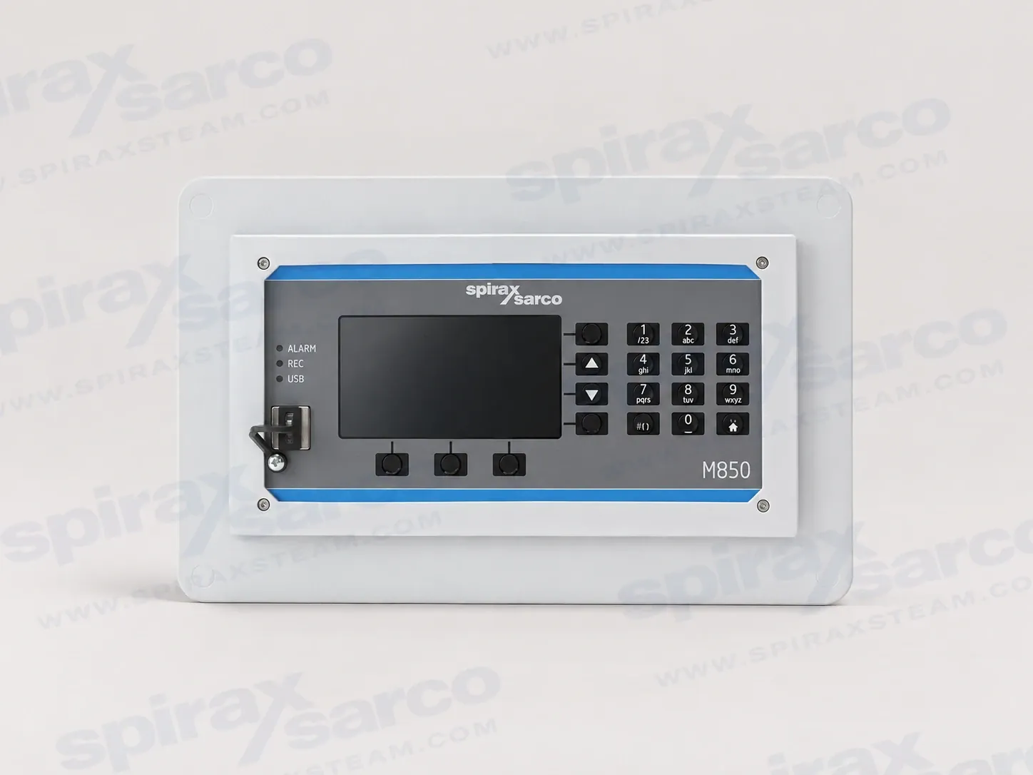
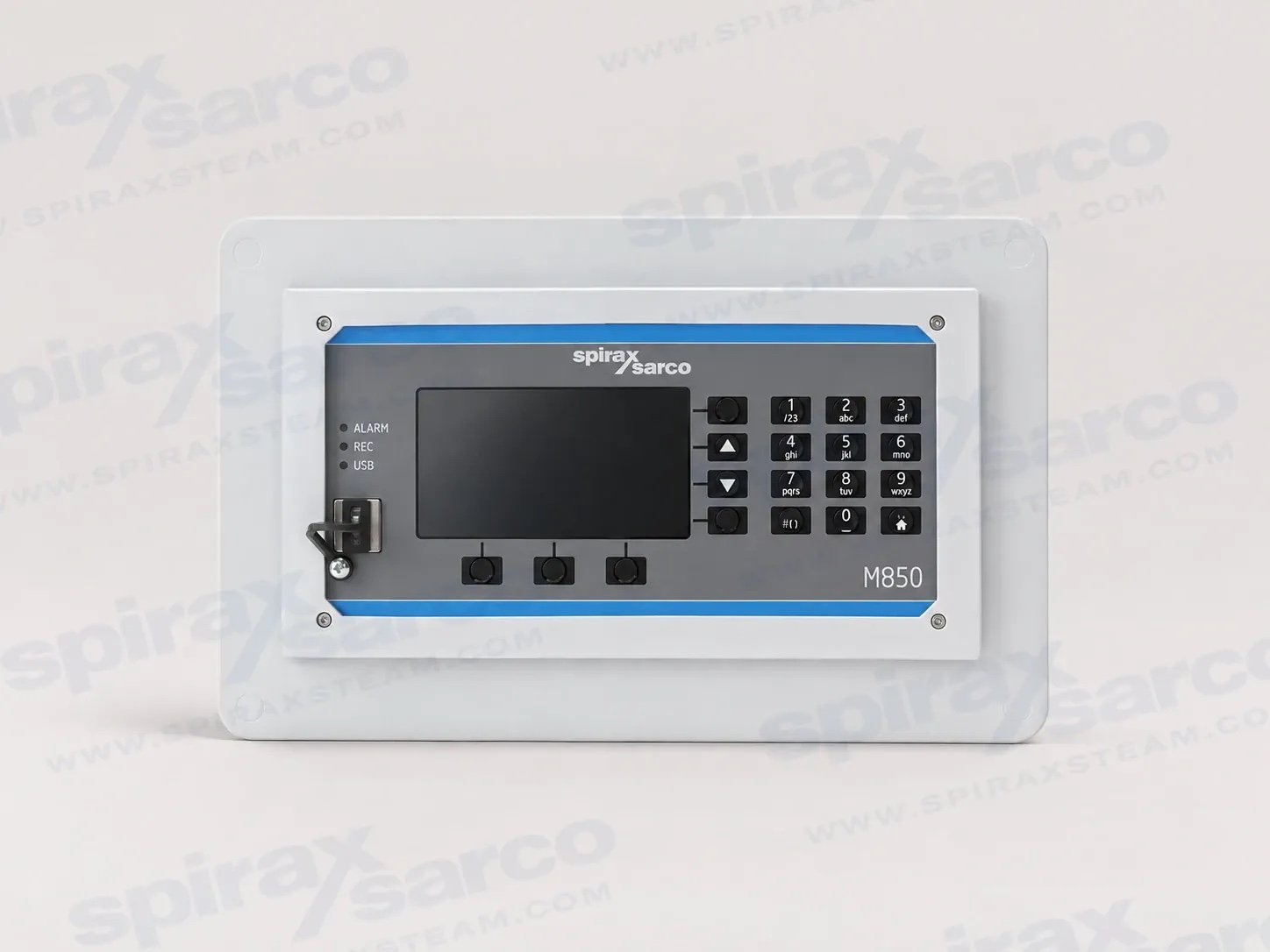
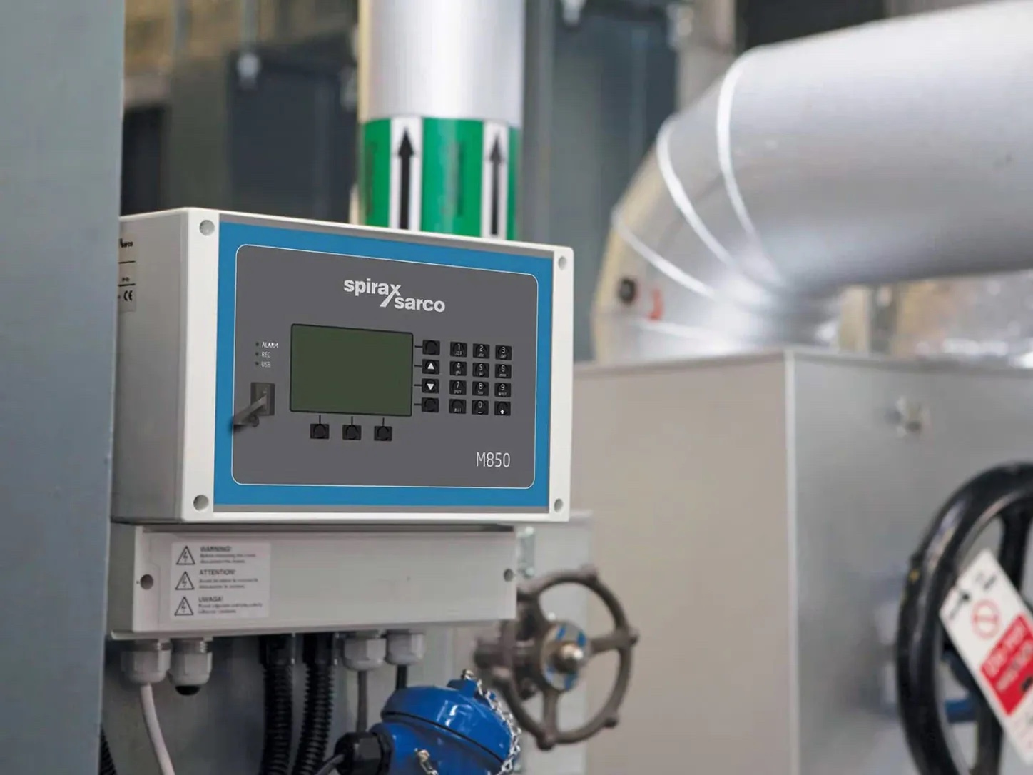
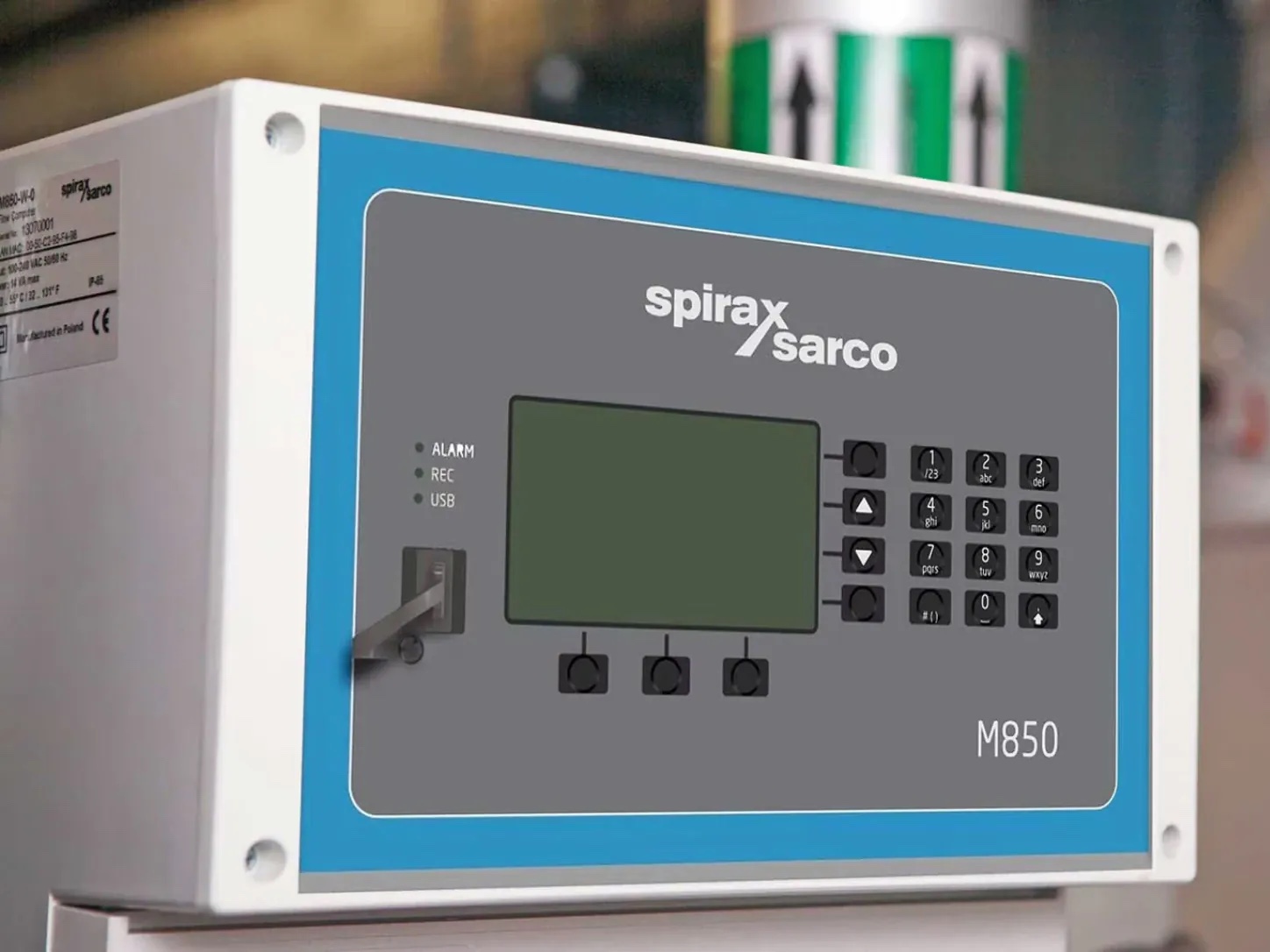
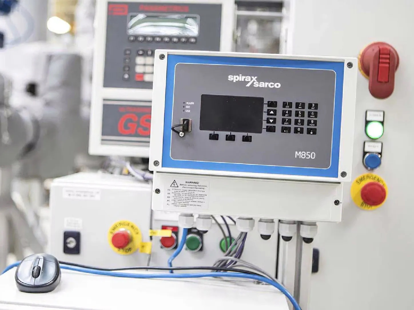
Spirax Sarco M850 flow computer for compensated measurement
The Spirax Sarco M850 is a programmable flow computer for calculating mass flow and energy flow in steam, gas and liquid applications. It sits between the flowmeter system and the operator or plant control network, combining transmitter signals, fluid properties and configured calculation rules into usable process values. The result can be displayed locally, totalised, recorded, sent to a supervisory system or used to trigger an alarm or simple control function.
The M850 is suited to flowmetering installations that need more than a local indication. It can receive differential-pressure, volume-flow or mass-flow signals and can use pressure and temperature information for compensated measurement. The device is documented for systems using Gilflo, ILVA, linear flowmeters and orifice plate assemblies. The selected meter, transmitter range, fluid and required calculation must still be checked against the application before an order is placed.
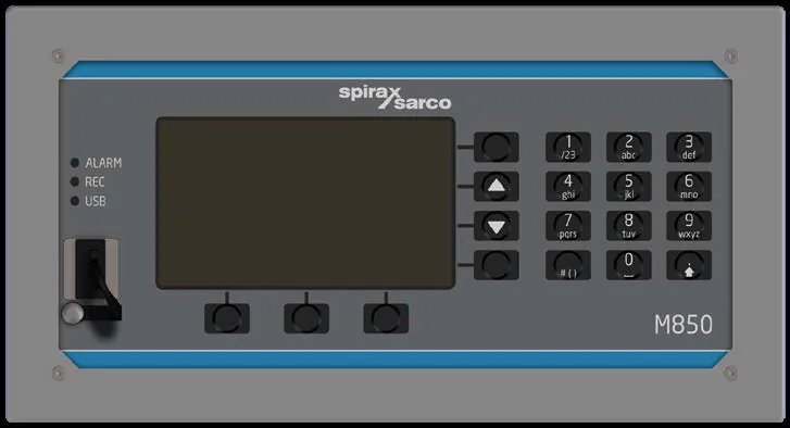
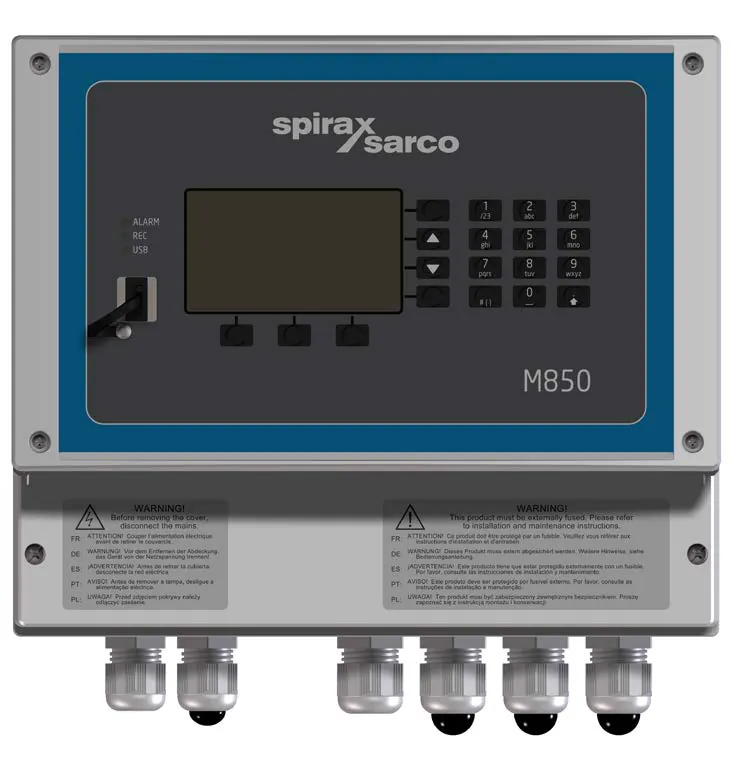
One flow computer, two installation formats
The M850-W-x is the wall-mounted version and is designed around a 100-240 Vac supply. The M850-P-x is the panel-mounted version and uses a 24 Vdc SELV supply. Both versions use the same measurement and calculation concept, so the physical format can be selected around the control-panel layout, available power and enclosure arrangement rather than by sacrificing the core flow-computing functions.
Each format is available with three output configurations. The -0 version has no optional analogue current output, -1 has one passive 4-20 mA output and -2 has two. Four binary outputs remain available for alarm, signalling or pulse functions, with the output hardware differing between the wall and panel variants. This nomenclature should be confirmed against the required supply, output type and local certification at quotation stage.
Measurement inputs and calculation functions
The M850 provides twelve measurement inputs. Six accept 0-20 mA or 4-20 mA current-loop signals, three accept four-wire RTD sensors, and three are configurable pulse, frequency or binary inputs. The current inputs can be used with passive transmitters supplied by the M850 or with active current-source transmitters. The device provides a 24 Vdc transmitter supply with a stated maximum of 22 mA per channel, while the input circuits and protection limits remain subject to the technical data.
The three RTD channels support Pt-100 x K and Ni-100 x K sensor arrangements. The documented ranges extend from -200 to +850 C for Pt-100 x K and from -60 to +150 C for Ni-100 x K. Wire-resistance compensation and four-wire connection are available for temperature measurement. The pulse inputs can monitor a contact state, measure frequency or count pulses from a meter with a fixed pulse value; this makes the same input group useful for different meter output arrangements.
Configured mathematical channels can use measured values, calculated values and constants to create additional process values. The quickstart guide describes flow and energy balances, averages, ratios, totalisers and event recording as examples of the functions available in the device. A one-second calculation update rate is specified for compensated flow and heat-energy measurement. The technical sheet gives typical accuracy better than plus or minus 0.5 percent, with a worst-case figure better than plus or minus 2 percent for the listed steam, water, other-liquid and technical-gas measurement. These figures do not replace a system-specific uncertainty assessment.
Local display, recording and communications
A backlit 3.5 inch colour TFT display presents measurement values, calculations, totals, alarms and configurable screens. Three two-colour indicators identify alarm, recording and USB status, while the 19-button membrane keypad supports local navigation and setup. The internal memory can record process values and events, allowing the flow computer to retain information where a permanent computer-network connection is not available.
For plant integration, the M850 provides an RS-485/RS-422 interface and an RJ-45 Ethernet port. The technical information lists ASCII, Modbus RTU and BACnet MSTP functions for the serial interface, and Modbus TCP, BACnet IP, HTTP server, DHCP server and ICMP functions for Ethernet. A USB 2.0 Type-A port supports the documented configuration and data-transfer workflow. Optional passive 4-20 mA outputs can retransmit a selected measured or calculated value to a receiver with an external loop supply.
These interfaces allow one configured instrument to serve several information tasks: local operator viewing, a plant historian or building-control network, hardwired alarm signalling and analogue retransmission. The exact protocol, address, baud rate, loop supply and data map should be agreed with the control-system designer before commissioning.
Engineering value for steam and utility systems
For steam measurement, the M850 can use the pressure and temperature signals needed to distinguish saturated and superheated conditions in a configured application. For water and other liquids, the calculation uses the relevant fluid characteristics entered during setup. For technical gases, the meter and transmitter data must be matched to the configured measurement method. In every case, the flow computer calculates from the signals it receives; it does not correct an incorrectly sized meter, a misranged transmitter or an unsuitable sensor installation.
The flowmeter is therefore part of the selection decision. Visit the flowmetering product range and compare the target flowmeter range to review upstream meter options, then confirm the M850 input arrangement, pressure and temperature compensation, pulse value or calibration coefficients. The M850 documents describe ILVA, Gilflo and M410/orifice differential-pressure examples for the supplied quickstart software. Other meter types, extra inputs and extended output assignments require the full installation and maintenance reference.
Installation and environmental limits
The M850 is specified for indoor installation. The wall version uses an IP65 enclosure when the cable-entry arrangement is correctly installed; the panel version provides IP65 protection at the front and IP20 at the rear. The documented operating temperature is 0 to +55 C with 5-95 percent non-condensing relative humidity, at altitudes up to 2000 m. Storage is specified from -30 to +70 C.
Choose a location away from excessive heat, vibration, shock, flooding, motors, large transformers and other sources of electrical or magnetic interference. A wall-mounted unit uses three 5 mm mounting points and requires suitable IP65 glands or conduit. A panel-mounted unit requires a 186 x 92 mm aperture, its supplied seal and fixing clamps. The rear of a panel unit needs clearance for wiring and viewing access; the installation guide illustrates a minimum 10 cm clearance around the rear unit in an enclosure.
Electrical work must be completed by suitably qualified personnel. The installation guide requires mains isolation before opening, appropriate overcurrent protection, an accessible disconnect device, compliant wiring and correct cable-screen connection. The wall variant uses hazardous mains voltage, while the panel variant uses a 24 Vdc SELV supply. The technical and installation sections below retain the terminal, isolation, wiring and safety conditions in full.
What to confirm before ordering an M850
Whether the wall-mounted M850-W-x or panel-mounted M850-P-x enclosure and supply match the installation.
The flowmeter technology, nominal range, output signal and calibration information.
Whether the application needs pressure, temperature or both for compensation.
The required number of optional passive 4-20 mA outputs and the available external loop supply.
The binary output load, communication protocol, network topology and recording requirements.
The required certification or inspection report, which the technical sheet says must be specified when ordering.
The indoor location, panel aperture or wall fixing arrangement, IP protection and cable-entry method.
When specifying the Spirax Sarco M850, treat the product code, meter data, sensor ranges and control-system interfaces as one engineering selection. This keeps the flow computer, transmitters and flowmeter aligned and gives commissioning personnel the information needed to reproduce the intended calculation.
Description
The M850 is a flexible flow computer for calculating mass flow and energy flow for steam, gas and liquid applications. It is intended to work as part of a flowmetering system and can be configured for a range of transmitter and meter technologies.
Standards and certification
The source document states that the products comply with the stated European Directives and UK legislation and carry the corresponding conformity markings. A cULus-certified wall-mount variant is available. An uncertainty certificate or inspection report can be supplied when the certification requirement is stated at the time of order.
Available options
Both enclosure versions provide the same core functions. M850-P is for panel mounting and uses 24 Vdc. M850-W is for wall mounting and uses 100-240 Vac. Each version can be fitted with one or two optional analogue 4-20 mA outputs.
M850 product nomenclature | |
Code element | Meaning |
|---|---|
M850-P | Panel-mounted version, CE approved as standard. |
M850-W | Wall-mounted version, CE approved as standard. |
-0 | No optional 4-20 mA analogue output. |
-1 | One optional 4-20 mA analogue output. |
-2 | Two optional 4-20 mA analogue outputs. |
Front panel
Display type | Colour TFT LCD, 3.5 inch, with LED backlight |
|---|---|
Display size and resolution | 43.8 mm x 77.4 mm; 272 RGB x 480 pixels |
LED indication | Three two-colour red/green LEDs for ALARM, REC and USB |
Keyboard | 19 membrane buttons |
Inputs
Input organisation | ||
Input group | Quantity | Terminals |
|---|---|---|
Current loop analogue | 6 x I type, 0/4-20 mA | IN1-IN6 |
RTD | 3 x four-wire RTD | IN7-IN9 |
Pulse | 3 x PULS | IN10-IN12 |
I type current loop inputs
Signal type | 0-20 mA or 4-20 mA |
|---|---|
Transmitter connection | Two-wire passive transmitter supplied from M850, or active current-source transmitter |
Input resistance | 95 ohm +/-10%, protected by a PTC 50 mA fuse in series |
Transmitter supply | 24 Vdc +10%/-20%; maximum 22 mA per channel, with PTC 50 mA fuse and 100 ohm resistor in series |
A/D converter resolution | 18 bit, using a 24 bit Sigma-Delta ADC |
50/60 Hz filter | Sinc3 digital filter |
Damping | First-order low-pass software filter time constants: 2 s, 5 s, 10 s, 20 s, 30 s, 1 min, 2 min, 3 min or 5 min |
Measurement resolution | Greater than 0.01% of full scale |
Accuracy at 25 C (77 F) | +/-0.1% of full scale; typical +/-0.05% of full scale |
Temperature drift | Maximum +/-0.02% of full scale per C |
Maximum input voltage | +/-40 Vdc / SELV |
Isolation between inputs | No; common potential of functional ground for all inputs |
Isolation to analogue outputs, RS-485/RS-422 and Ethernet | 250 Vac continuous; 1500 Vac for 1 minute |
RTD inputs
Sensor types | Pt-100 x K and Ni-100 x K, where K = 1-11 |
|---|---|
Measuring range | Pt100 x K: -200 to +850 C (-328 to +1562 F); Ni100 x K: -60 to +150 C (-76 to +302 F) |
Sensor connection | Four-wire, or two-wire with wire bridges |
Wire-resistance compensation | Automatic, with additional manual range -99.99 to +99.99 ohm |
Maximum connecting-wire resistance | 50 ohm |
A/D converter resolution | 18 bit, using a 24 bit Sigma-Delta ADC |
50/60 Hz filter | Sinc3 digital filter |
Damping | 2 s, 5 s, 10 s, 20 s, 30 s, 1 min, 2 min, 3 min or 5 min |
Measurement resolution | Greater than 0.05% of reading or 0.1 ohm |
Accuracy at 25 C (77 F) | +/-0.5 C (+/-0.9 F); typical +/-0.3 C (+/-0.54 F) |
Temperature drift | Maximum +/-0.02 C per C (0.036 F per F) |
Maximum input voltage | +/-40 Vdc / SELV |
Isolation | No isolation between inputs; 250 Vac continuous and 1500 Vac for 1 minute to analogue outputs and communications |
PULS inputs
Measuring range | 0-20 kHz, with cut-off below 0.001 Hz; 0-1 kHz with filter jumper J1/J2/J3 ON |
|---|---|
Minimum pulse width | 25 microseconds; 0.5 ms with filter jumper J1/J2/J3 ON |
Frequency accuracy at 25 C | 0.02% |
Default configuration | OC or contact open/closed, with internal jumper J4/J5/J6 ON |
Open-circuit voltage | 5 Vdc |
Short-circuit current | 5 mA |
On/off threshold | 2.7 V / 2.4 V |
Voltage-input configuration | Internal jumper J4/J5/J6 OFF; signal amplitude 4-36 Vdc; input resistance at least 10 kohm |
Maximum input voltage | +/-40 Vdc / SELV |
Isolation | No isolation between inputs; 250 Vac continuous and 1500 Vac for 1 minute to analogue outputs and communications |
Compensated flow and heat-energy measurement
Calculation update rate | 1 s |
|---|---|
Total accuracy of compensated steam, water, other liquid or technical-gas measurement | Typical: better than +/-0.5%; worst case: better than +/-2% |
Optional 4-20 mA analogue outputs
Number of outputs | 1 or 2 |
|---|---|
Output signal | Passive 4-20 mA; external current-loop supply required |
Resolution | 16 bit DAC |
Loop resistance at UCC = 24 V | 0-600 ohm |
Minimum loop supply | UCCmin = RL x 0.022 + 8 |
Maximum loop supply | 28 Vdc / SELV |
Accuracy at 25 C (77 F) | Better than +/-0.2% of full scale |
Temperature drift | Maximum +/-0.02% of full scale per C |
Isolation | 250 Vac continuous; 1500 Vac for 1 minute to analogue inputs, RS-485/RS-422 and Ethernet |
Binary outputs
M850-W-x
Number | 4 |
|---|---|
Type | Three-pole COM, NO, NC electromechanical relay |
Contact rating | 3 A at 85-250 Vac / 30 Vdc, resistive load |
Maximum switching voltage | 250 Vac / 125 Vdc |
M850-P-x
Number | 4 |
|---|---|
Type | Two-pole solid-state relay |
Contact rating | 0.1 A at 24 Vac/dc; maximum 42 Vac or 60 Vdc / SELV |
Maximum ON resistance | 20 ohm |
Galvanic isolation | 250 Vac continuous; 1500 Vac for 1 minute |
Communications
RS-485 / RS-422
Transmission protocols | ASCII, Modbus RTU, BACnet MSTP and GSM |
|---|---|
Network size | Up to 256 nodes |
Maximum line length | 1200 m, depending on data-cable quality and baud rate |
Baud rates | 2.4, 4.8, 9.6, 19.2, 38.4, 57.6, 115.2 or 230.4 kbps |
Parity | Even, odd or none; one start bit, eight data bits, parity bit and one stop bit |
Termination | Internal terminating resistor, activated with a DIP switch |
Frame and electrical limits | One start bit, eight data bits, parity bit and one stop bit; bus terminal voltage -8 to +13 Vdc / SELV; minimum driver differential output 1.5 V at RL = 54 ohm; minimum receiver sensitivity 200 mV |
Protection | Short-circuit and thermal protection |
Isolation | 250 Vac continuous; 1500 Vac for 1 minute to analogue inputs, analogue outputs and Ethernet |
Ethernet and USB
Ethernet protocols | Modbus TCP, ICMP (ping), DHCP server, HTTP server and BACnet IP |
|---|---|
Ethernet interface | 10 BaseT Ethernet, RJ-45 / SELV |
Data buffer | 300 B |
Simultaneous connections | 4 |
USB | Type-A socket, USB 2.0, FAT16 recording format within a limited scope |
Ethernet indication | Two LEDs built into the RJ-45 socket |
Power supply and terminals
Item | M850-W-x | M850-P-x |
|---|---|---|
Rated supply | 100-240 Vac, 50/60 Hz | 24 Vdc, SELV and limited-energy supply |
Supply range | 85-264 Vac, 47-63 Hz | 18-36 Vdc |
Maximum consumption | 20 VA | 8 W |
Terminals | Spring-type terminal block | Plug-in screw-type terminal blocks |
Conductor range | Solid 0.2-2.5 mm2; stranded 0.2-1.5 mm2; ferrule 0.25-1.5 mm2; AWG 26-12 | Solid 1.5 mm2 maximum; stranded 1 mm2 maximum; ferrule 0.25-1.5 mm2; AWG 30/14 |
Cable entry | Non-cULus: four M20 glands and two M16 glands. cULus: four 1/2 inch NPT conduit hubs. | Panel terminal arrangement |
Package dimensions | 290 mm x 300 mm x 165 mm | 135 mm x 230 mm x 110 mm |
Package gross weight | Approximately 2.5 kg for cULus version | Approximately 0.7 kg |
Enclosures and environmental conditions
Item | M850-W-x | M850-P-x |
|---|---|---|
Enclosure | Wall mounting, polycarbonate | Panel mounting, Lexan Resin 920 |
Dimensions without accessories | 217 mm x 257 mm x 134 mm (height x width x depth), without cable glands | 110 mm x 206 mm x 63.5 mm, without terminals |
Dimensions with entry/terminals | 247 mm x 257 mm x 134 mm with non-cULus cable glands; 238 mm x 257 mm x 134 mm with cULus conduit hub | 110 mm x 206 mm x 72 mm with terminals |
Weight | Approximately 1.7 kg net; cULus version approximately 2.5 kg gross | Approximately 0.6 kg net and 0.7 kg gross |
Protection | IP65 | IP65 front / IP20 rear |
Panel cut-out | Not applicable | 186 mm x 92 mm |
Panel thickness | Not applicable | 1-5 mm |
Ambient temperature | 0 to +55 C (32 to 131 F) |
|---|---|
Relative humidity | 5-95%, non-condensing |
Altitude | 2000 m (6562 ft) maximum above sea level |
Storage temperature | -30 to +70 C (-22 to +158 F) |
Pollution degree | 3 for panel version when installed in an enclosure; 3 for wall version |
Electrical safety | EN 61010-1; CAN/CSA-C22.2 No. 61010-1, 3rd Edition |
EMC | Immunity EN 61326-1 Table 2; radiated and conducted emissions EN 61326-1 Group 1 Class B |
Installation location | Indoor use only |
Approximate dimensions and weights
Version | A | B | C | D | E | Weight |
|---|---|---|---|---|---|---|
M850-W-x wall mounted | 257 mm | 217 mm | 134 mm | 30 mm* | - | 1.70 kg |
M850-P-x panel mounted | 206 mm | 110 mm | 72.3 mm | - | 9.5 mm | 0.60 kg |
* The dimension marked with an asterisk is approximate because the cable glands are adjustable. The detailed enclosure dimensions and panel cut-out requirements above take precedence for installation planning.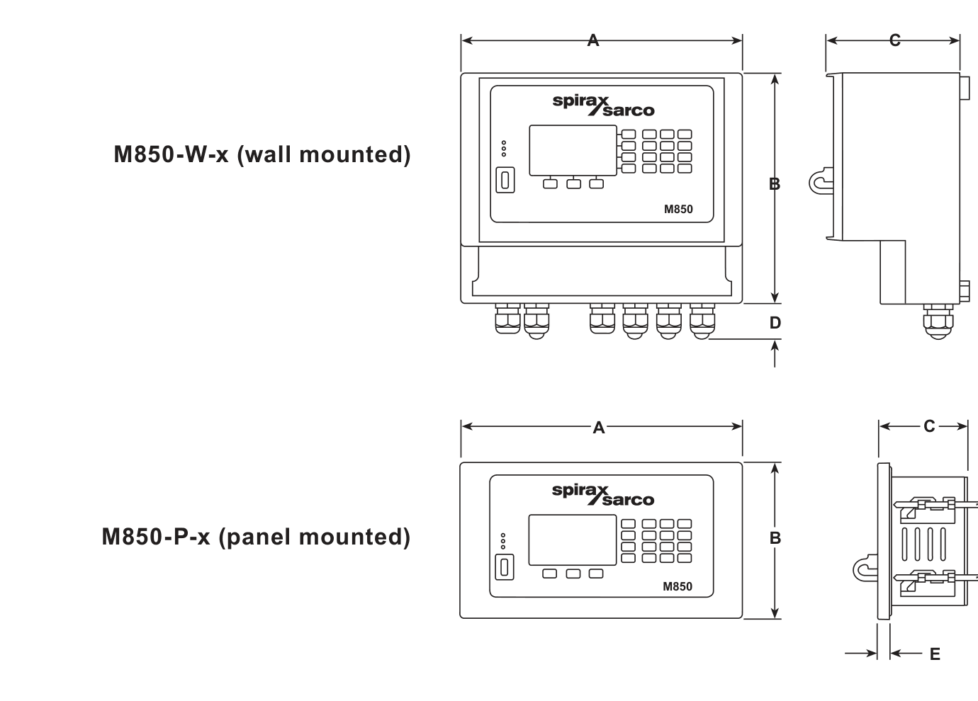
Safety, installation and ordering notes
The wall-mounted M850-W-x requires three mounting screws, not supplied, and can optionally use DIN-rail mounting.
The panel-mounted M850-P-x is supplied with mounting clamps and requires the documented panel seal.
An adaptor plate is available as a separate kit for replacement installations where the M850 replaces an existing M200 or M800 flow computer.
State all certification and inspection requirements when placing the order.
There are no spare parts available for the M850 flow computers.
Examples of the nomenclature are M850-P-1 for a panel-mounted unit with one optional 4-20 mA output and M850-W-2 for a wall-mounted unit with two. Before ordering, revisit the option nomenclature and confirm the required enclosure, supply and optional analogue-output configuration for the intended application.
This quickstart information covers safe installation, connection and initial commissioning of the M850-W wall-mounted and M850-P panel-mounted flow computers. The full installation and maintenance instructions remain the reference for extended configurations.
Safety information
Safe operation depends on correct installation, commissioning, use and maintenance by qualified personnel in accordance with the operating instructions and applicable plant, wiring and safety rules. The M850 is for indoor installation only.
Electrical and product safety
Isolate the mains supply before opening the product because hazardous voltages may be exposed. Do not use the product outside its intended flow-computer application, modify it, or repair it outside the documented service arrangements. Incorrect installation or modification can damage property, injure personnel, invalidate conformity markings and compromise the complete system.
Work area and access
Provide safe access, a guarded working platform where necessary and adequate lighting. Assess the surrounding environment for explosion risk, lack of oxygen, dangerous gases, hot surfaces, fire risk, moving machinery, excessive noise and extreme temperatures before work starts.
System isolation
Consider the effect of the work on the whole system. Closing isolation valves or disconnecting power must not remove protection or put other personnel at risk. Operate process isolation valves gradually to avoid system shocks, and use the required permits and warning notices.
Handling and disposal
Assess the manual-handling risk of lifting, pushing or supporting the equipment and use suitable lifting equipment when required. The M850 contains a battery; dispose of the unit or battery in accordance with local and national regulations. The remaining product is recyclable when handled correctly.
When returning equipment, provide written information about contamination residues, mechanical damage and any health, safety or environmental precautions. Return the equipment suitably packed through the local Spirax Sarco representative.
Standards and maintenance
Wiring materials and methods must comply with the applicable EN and IEC standards. UK installations should observe IEE Regulations BS 7671; other locations should follow the applicable local rules. The guide identifies EN 61010-1 electrical safety and EN 61326-1 immunity and emissions requirements. For US and Canadian installations, select NEC Class 1 wire with a temperature rating above 75 deg C unless a higher rating is required by the cable environment. No special servicing, preventative maintenance or inspection is required; clean the unit with a dry cloth only and do not use detergent or water. There are no user-serviceable parts.
Delivery, handling and storage
Each M850 is tested, calibrated and inspected before shipment. Inspect the carton at delivery, record visible damage on the carrier's delivery documentation and unpack the contents carefully. Report missing or damaged items to Spirax Sarco and the carrier without delay.
M850-P package
One M850-P flow computer.
Two fixing clamps.
Printed quickstart guide.
USB containing the full installation and maintenance instructions and configuration software.
One set of terminal blocks and the carton package.
M850-W package
One M850-W flow computer.
Printed quickstart guide.
USB containing the full installation and maintenance instructions and configuration software.
The carton package.
Storage
Store the flow computer between -30 and +70 deg C (-22 and +158 deg F) and at 5-95 percent relative humidity, non-condensing. Before connecting power, make sure that no condensation is present inside the unit.
Purpose and basic functions
The M850 is a microprocessor-based universal flow computer for steam and water flow and heat calculations according to IAPWS-IF97, liquid-flow and heat calculations using user-provided characteristics, and technical-gas flow measurement. It forms part of a flowmetering system and can be used with ILVA, Gilflo, orifice and nozzle differential-pressure devices according to PN EN ISO 5167 where applicable, volume flowmeters and mass flowmeters.
The configured instrument can operate as an independent measurement device or as part of a computerised measurement and control system. Mathematical functions calculate flow and energy balances, averages, ratios and other values. Totalisers, process-value recording and event logging support analysis of operating conditions and alarm states, including installations beyond the reach of a permanent computer network.
Twelve inputs, four relay outputs and optional passive 4-20 mA outputs support measurement, signalling and simple control. The display and keypad provide local configuration and results viewing, while RS-485 and Ethernet support connection to a supervisory system. The M850-P is panel mounted and powered by 24 Vdc; the M850-W is wall mounted and powered by 100-240 Vac.
Mechanical installation
Install every version indoors, away from excessive heat, electrical interference, external magnetic fields, vibration, shock and areas liable to flooding. The wall version cable-entry arrangement must provide the documented IP protection in accordance with EN 60529. Allow clearance for conduit and wiring and for viewing the display. A panel unit also requires a minimum 10 cm clearance around the rear unit inside its enclosure.
Wall-mounted M850-W
Use the documented dimensions to drill three holes suitable for 5 mm (No. 10) screws.
Remove the terminal-enclosure cover to expose the lower mounting holes.
For a non-cULus version, fit cable glands or conduit with a minimum IP65 rating, or install the unit in a clean, dry room providing the required pollution-degree environment. Seal unused entries with suitable blind grommets.
Fit the top M5 screw with its head proud enough for the top mounting lug to slide over it.
Slide the top lug over the screw, align the lower mounting holes and fit the remaining screws.
Refit the terminal-enclosure cover. Use the cULus conduit-hub arrangement where that certified version is selected.
Panel-mounted M850-P
Provide a rectangular panel aperture 186 mm wide by 92 mm high.
Fit the supplied IP65 seal between the flow computer and the panel, then push the M850-P through the aperture.
From the rear, assemble the supplied fixing clamps to the mounting points on the sides of the flow computer.
Carefully tighten the clamps through their screwdriver slots until the unit is secure in the panel.
A separate blanking panel is available for replacement installations where an existing M800 opening needs to be adapted to the M850. Confirm the selected accessory and opening before ordering.
Electrical installation
Electrical work must be performed by personnel qualified to work on equipment containing hazardous live voltages. Read the safety information before wiring and isolate the flow computer before opening it.
Use the building installation for primary isolation and overcurrent protection. Install 1 A overcurrent protection in every phase conductor as required by the guide; protect relay circuits with devices rated for their actual load.
Use a disconnecting switch or circuit breaker close to the equipment and accessible to the operator. It must disconnect all phase conductors, be clearly identified, retain the protective-earth conductor and comply with IEC 60947-1 and IEC 60947-3.
Install wiring to IEC 60364 and the applicable national or local electrical code. Maintain double or reinforced insulation between hazardous live mains/relay circuits and SELV signal circuits.
Secure conductors close to the terminal block so a loosened wire cannot contact accessible parts. Relay contacts must be supplied from the same phase as the product mains supply.
Connect cable screens as shown in the wiring arrangement. The earth terminal is a functional earth used to drain interference and is not a protective-earth terminal; connect screens at one end as specified to avoid an earth-current loop.
The M850-W uses the 100-240 Vac supply and the M850-P uses a 24 Vdc SELV, limited-energy supply. Confirm terminal numbers, output loading, transmitter supply and the selected wiring diagram before energising.
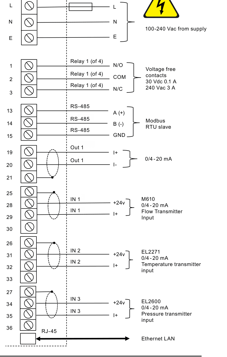
The wiring diagrams show relays and switches in the power-off position. Do not use the wiring illustration as a substitute for the applicable local electrical code or for checking the product label and selected variant.
Commissioning
The flow computer can be commissioned from its front keypad or with the supplied PC software. The quickstart sequence uses the PC software for a stand-alone differential-pressure flowmeter installation based on a Spirax Sarco ILVA, Gilflo or M410 orifice-plate system. Use the full IM-P333-26 instructions for other flowmeter types or additional inputs and outputs.
Install the supplied commissioning software on the PC and select the working language.
Choose File / New Settings, select imperial or metric units and enter an identification tag for the flowmeter installation.
Open Configure the installation, select the steam-flow application and choose saturated or superheated steam as applicable.
For saturated steam, select pressure or temperature as the compensation measurement. For superheated steam, use both pressure and temperature to calculate density compensation.
Select the differential-pressure device, then choose the ILVA, Gilflo or M410 orifice option. Enter the flowmeter calibration coefficients or orifice data from the supplied certificate or plate information.
Assign the pressure transmitter and differential-pressure cell to the required inputs. Set titles, units and transmitter ranges, including the pressure range; the guide's example uses 0 bar g at 4 mA and 10 bar g at 20 mA.
Review the archive and main screen, add the mass-flow result and any required pressure value, then review the 4-20 mA output and media-manager screens.
Complete the configuration, save the file on the PC and copy it to a USB memory stick so it can be transferred to the M850.
Check the meter size, calibration coefficients, transmitter ranges, engineering units, compensation method, output assignments and communication settings before commissioning the live installation.
Symbols of failure
When a measurement channel fails, the M850 displays the relevant failure symbol instead of the result for the affected channel and any calculation that uses it.
Symbol | Meaning |
|---|---|
-F- | RTD sensor failure or no signal from the assigned sensor. |
-||- | 4-20 mA transducer current below 3.6 mA. |
-E- | 4-20 mA transducer current above 22 mA. |
-S- | Steam parameters below the saturation curve when saturation detection is enabled. |
-R- | Measurement range exceeded. |
-W- | Waiting after power-on while data is not ready. |
-C- | Internal communication error. |
A detected failure can display a message and require user confirmation even after the original cause has ended. Depending on the programming, the related output relay may remain active until confirmation or for the duration of the failure, and the event can be recorded. If a GSM module is connected to RS-485, failure information can be sent by text message.