
SV73 cast iron safety valve for ASME boiler and pressure vessel protection
The Spirax Sarco SV73 is a semi-nozzle, full-lift safety valve with a grey cast iron body and stainless steel trim. It is built in conformance to Section I and Section VIII of the ASME Boiler and Pressure Vessel Code and is primarily intended for power boilers and unfired pressure vessels where ASME stamped valves are required. National Board of Boiler and Pressure Vessel Inspectors certification covers its design and capacity, and each valve can be stamped with the ASME 'V' symbol for Section I service or the 'UV' symbol for Section VIII service when this is specified at the time of ordering.
For the engineer selecting protection for a steam plant, Spirax Sarco SV73 provides a documented route from the protected equipment to the valve: orifice size, inlet and outlet connection, set pressure, discharging medium, overpressure allowance and discharge arrangement are all specified together rather than treated as independent choices. The figures and detailed tables later on this page carry the full engineering data; this introduction explains what the valve is, where it fits, and which conditions must be confirmed before ordering.
Product role and typical applications
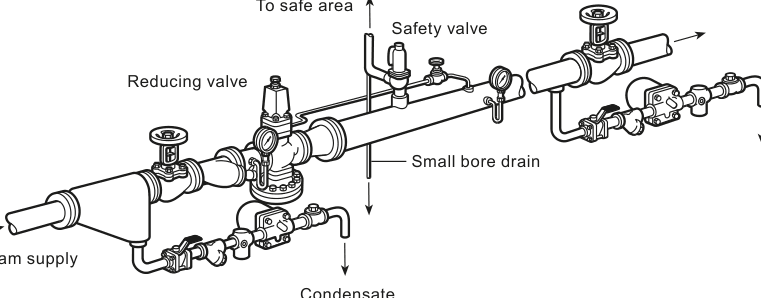
A full-lift safety valve opens rapidly when the protected system reaches its set pressure, providing the orifice area needed to control an overpressure event. The SV73 is documented for steam, air and other inert industrial gases. Its documented applications include protection of steam systems downstream of pressure regulating stations; inlet protection on equipment such as air coils, heat exchangers and process vessels; protection of flash recovery vessels on condensate return systems; protection of air accumulation vessels and air equipment; and steam boilers and generators.
One characteristic of the SV73 defines where it can be used. Because the body, bonnet and cap are manufactured in grey cast iron, the valve does not fall within the scope of the Pressure Equipment Directive, so the SV73 is not CE marked and must not be used on any installation within the European Economic Area. For applications inside the EEA, the design should be routed to a PED-compliant valve family instead. Within its documented scope, Spirax Sarco SV73 suits power boiler and unfired pressure vessel duties that require ASME Section I or Section VIII stamped valves.
Construction and how the valve works
The SV73 is a semi-nozzle full-lift valve. The seat and disc assembly lifts fully off the nozzle once the inlet pressure overcomes the spring compression, giving a rapid pressure-relieving action; the valve reseats when system pressure falls back below the closing point. The stainless steel trim — including the seat, disc, adjusting rings, stems and spring washers — works against the cast iron body, bonnet and cap, and the open bonnet with easing lever allows manual lifting for test purposes.
Two adjustments govern the operating behaviour. The set pressure is the inlet pressure at which the valve begins to lift, selected between 5 psi g and 250 psi g; ASME code stamped valves require a minimum set pressure of 15 psi g. The blowdown is the pressure drop required for the valve to reseat, and it is controlled by the adjusting rings during commissioning by an authorised facility. The valve is supplied tested and sealed to prevent unauthorised adjustment, and the derated coefficient of discharge is 0.955 for steam and for air/gas service.
Cast iron is a strong, low-cost body material for boiler duty, but it is brittle compared with ductile iron or steel. The installation and maintenance instructions treat this explicitly: if a valve is dropped during installation and there is any risk of damage, it must not be used unless it has been fully inspected and pressure tested by the manufacturer. The same instructions recommend insulating the inlet neck and body when the valve is installed outdoors to reduce the effects of temperature variation.
Pressure and temperature envelope
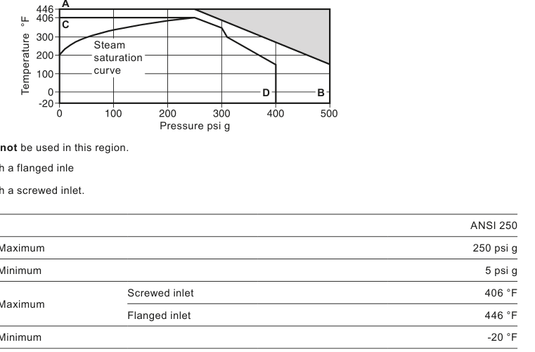
The SV73 body is designed for ANSI 250 service. The set pressure range runs from 5 psi g minimum to 250 psi g maximum, with ASME stamped valves starting at 15 psi g. Maximum temperature is 406 °F for valves with a screwed inlet and 446 °F for valves with a flanged inlet; the minimum is -20 °F. The pressure/temperature limits graph in the technical information below marks the region the product must not be used in, together with the A-B limit for flanged-inlet valves and the C-D limit for screwed-inlet valves — these curves, not the nominal ratings alone, define the safe operating envelope.
| Parameter | Limit |
|---|---|
| Body design condition | ANSI 250 |
| Set pressure range | 5 psi g min to 250 psi g max (15 psi g min for ASME stamped) |
| Maximum temperature | 406 °F screwed inlet / 446 °F flanged inlet |
| Minimum temperature | -20 °F |
| Overpressure | 3% ASME I steam; 10% ASME VIII steam; 10% air/gas |
| Blowdown | 2-6% ASME I steam; 7% ASME VIII; 7% air/gas |
| Derated coefficient of discharge | 0.955 (steam and air/gas) |
| Maximum permitted backpressure | 10% of set pressure |
| Cold hydraulic test | 600 psi g maximum inlet |
Backpressure deserves particular attention during station design. Accumulated backpressure at the valve outlet reduces relieving capacity, and the instruction is a hard limit: built-up backpressure must not exceed 10% of the gauge set pressure. Discharge pipework must be routed to a safe area, supported independently of the valve, and drained at its lowest points.
Sizes, connections and orifice selection
The SV73 is offered in screwed and flanged routes sized from 1½" x 2½" up to 6" x 8". The screwed route uses female NPT inlet and outlet connections from 1½" x 2½" to 3" x 4". The flanged-inlet routes pair an ANSI 250 RF inlet with either a screwed NPT outlet (1½" x 2½" to 3" x 4") or an ANSI 125 FF outlet (3" x 4" to 6" x 8"). A ½" NPT drain hole connection is fitted on all sizes. Orifice letters run from J to R, giving orifice areas from 1.374 to 17.123 square inches; the dimensions, weights and orifice table in the technical information lists every size combination.
Selecting the orifice is the core sizing step: the required relieving capacity, the set pressure, the overpressure allowance and the ASME section determine the orifice letter, which in turn fixes the size and connection letter used in the order code. The sizing formulas and superheat correction table are reproduced in the technical information so the calculation can be performed against the valve's derated coefficient of discharge.
Ordering and what to confirm before purchase
Each SV73 is ordered through the SV7 selection code: series SV7, construction 3 for cast iron, the ASME section (V for Section I, U for Section VIII, or blank for a valve without code stamp), the size and connection letter, the orifice letter and the set pressure. The documented example is an SV73-V-AJ-180, a Section I valve with set pressure 180 psi g. Set pressures below 15 psi g are not ASME coded, and the 'V' or 'UV' National Board stamp must be specified at the time of ordering. Each valve ships with a Typical Test Report stating the valve set and hydraulic test pressure, and EN 10204 3.1 material certification is available on request.
Installation, commissioning and maintenance essentials
The spring housing centreline is installed vertically above the valve. The inlet connection between the vessel and the valve must have an area at least equal to the valve inlet, and no stop valve is permitted between the protected vessel and the safety valve except as allowed by ASME Section VIII UG-135(e). Pressure loss at the inlet should be no more than 3% of the pressure differential between set pressure and superimposed backpressure during discharge, and the valve is fitted 8 to 10 pipe diameters downstream of converging or diverging fittings or bends to avoid chattering and hammering. Pipework is blown through before the valve is fitted, and the valve is inspected for damage before installation.
During commissioning the set pressure is verified by raising system pressure, overpressure is checked against the 3% or 10% allowance for the ASME section, and the valve is confirmed to reseat at normal operating pressure. The test lever may only be operated when system pressure is at least 85% of set pressure. Planned maintenance continues in service: a visual inspection every two months and a complete pressure test at least annually. Valves that fail to open within 103% (ASME I) or 110% (ASME VIII) of the name-plate set pressure, or fail to open or close properly, must be removed for replacement or repair at an ASME-authorised facility. Leakage must never be stopped by compressing the spring or gagging the valve. For the complete installation, operation and maintenance requirements, see the SV73 installation and maintenance guide in the document section below.
Where the SV73 sits in plant protection
Safety valves are one element of a complete overpressure protection design. The Spirax Sarco SV73 belongs with the other equipment in a steam plant — pressure regulating stations whose downstream piping it protects, pressure vessels and boilers it guards, and the broader family of safety valves available for duties outside its cast iron envelope. Where a protected system operates inside the EEA, exceeds the ANSI 250 body rating, or requires a PED-marked valve, a different model from the safety valve range should be selected instead of stretching the SV73 beyond its documented limits.
Summary
The Spirax Sarco SV73 is an ASME Section I and VIII semi-nozzle full-lift safety valve in a cast iron body with stainless trim, sized from 1½" to 6" inlets in screwed and flanged connection routes. It combines National Board certified design and capacity with a 5-250 psi g set pressure range, a derated coefficient of discharge of 0.955 and a 10%-of-set backpressure limit. Its documented duties cover power boilers, unfired pressure vessels, and steam, air and inert gas systems, within the boundary that grey cast iron construction places it outside PED scope and outside the EEA. Confirming the ASME section, orifice, connection, set pressure and discharge arrangement together is what turns this selection into a compliant, stamped protection device for the application.
Scope of this technical information
This fragment preserves the SV73 technical information from TI-S13-25, CTLS Issue 13. The source data sheet covers the SV73 cast iron safety valve only. Local regulations may restrict the use of this product to below the conditions quoted. In the interests of development and improvement of the product, Spirax Sarco reserves the right to change the specification without notice.
Description
The SV73 cast iron series valves are built in conformance to Section I and VIII of the ASME Boiler and Pressure Vessel Code. They are primarily intended for use on power boilers and unfired pressure vessels where ASME Section I and VIII stamped valves are required.
Applications
- Protection of steam systems downstream of pressure regulating stations, on inlet to such equipment as air coils, heat exchangers and process vessels.
- Use on flash recovery vessels on condensate return systems to protect vessels.
- Air systems to protect accumulation vessels and air equipment from overpressurisation.
- Steam boilers and generators.
Available types
The SV73 is available with cast iron body and stainless steel trim in orifice sizes from 'J' to 'R'. It has an open bonnet and easing lever and is available with screwed or flanged connections.
Certification
A manufacturers' Typical Test Report is provided as standard for each valve which will include valve set and hydraulic test pressure. Also available on request is material certification in accordance with EN 10204 3.1.
Standards and approvals
- Approved by National Board of Boiler and Pressure Vessel Inspectors to ASME Boiler and Pressure Vessel Code Sections I and VIII.
- Seat tightness is in accordance with ANSI/API STD 527-1992.
- If National Board 'V' or 'UV' stamp is required, then this must be specified at the time of ordering.
Important note: SV73 safety valves are not CE marked and therefore not to be used within the EEA.
Sizes and end connections
| Inlet | Outlet | Connection arrangement |
|---|---|---|
| 1½" x 2½" to 3" x 4" | 1½" x 2½" to 3" x 4" | Inlet/outlet screwed female NPT |
| 1½" x 2½" to 3" x 4" | 1½" x 2½" to 3" x 4" | Inlet flanged ANSI class 250 RF, outlet screwed female NPT |
| 3" x 4" to 6" x 8" | 3" x 4" to 6" x 8" | Inlet flanged ANSI class 250 RF, outlet flanged ANSI class 125 FF |
Note: Drain hole connection ½" NPT on all valve sizes.
Pressure/temperature limits
| Item | Value |
|---|---|
| Body design conditions | ANSI 250 |
| Set pressure range — maximum | 250 psi g |
| Set pressure range — minimum | 5 psi g |
| Temperature — maximum (screwed inlet) | 406 °F |
| Temperature — maximum (flanged inlet) | 446 °F |
| Temperature — minimum | -20 °F |
| Overpressure — ASME I steam | 3% |
| Overpressure — ASME VIII steam | 10% |
| Overpressure — air/gas | 10% |
| Blowdown limits — ASME I steam | 2 - 6% |
| Blowdown limits — ASME VIII steam | 7% |
| Blowdown limits — air/gas | 7% |
| Derated coefficient of discharge — steam | 0.955 |
| Derated coefficient of discharge — air/gas | 0.955 |
| Maximum permitted backpressure | 10% of set pressure |
| Cold hydraulic test pressure | 600 psi g maximum inlet |
Materials
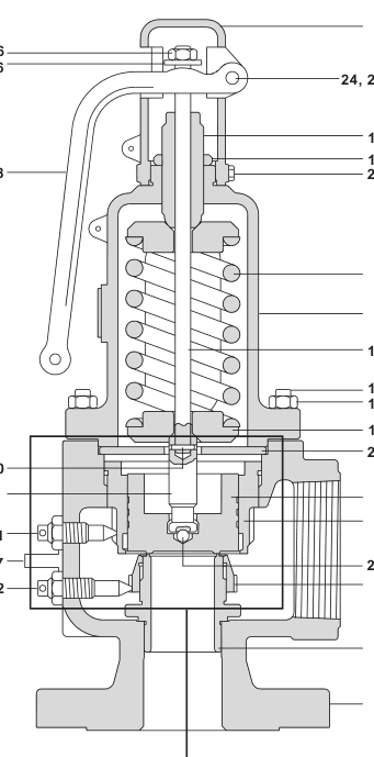
| No. | Part | Material |
|---|---|---|
| 1 | Body | Cast iron, ASTM A126 Class B |
| 2 | Seat | Stainless steel, ASTM A351 Grade CF8 |
| 3 | Bonnet | Cast iron, ASTM A126 Class B |
| 4 | Cap | Cast iron, ASTM A126 Class B |
| 5 | Disc | Stainless steel, ASTM A217 CA15 |
| 6 | Spring | Chrome-vanadium alloy steel |
| 7 | Upper adjusting ring | Stainless steel, ASTM A351 Grade CF8 |
| 8 | Lower adjusting ring | Stainless steel, ASTM A351 Grade CF8 |
| 9 | Stem (lower) | Stainless steel, ASTM A182/A182M-18 F6A Class 3 |
| 10 | Stem (upper) | Stainless steel, ASTM A479 Type 410 |
| 11 | Spring washers (2 off) | Steel, ASTM A105 |
| 12 | Bonnet stud | Steel, ASTM A193 Grade B7 |
| 13 | Bonnet nut | Steel, ASTM A194 Grade 2H |
| 14 | Adjusting screw | Stainless steel, ASTM A479 Type 410 |
| 15 | Adjusting screw nut | Carbon steel |
| 16 | Release ring | Carbon steel |
| 17 | Lock-nut (2 off) | Carbon steel |
| 18 | Lever | Grey iron |
| 20 | Cap set screw | Carbon steel |
| 21 | Upper adjusting ring pin | Stainless steel |
| 22 | Lower adjusting ring pin | Stainless steel |
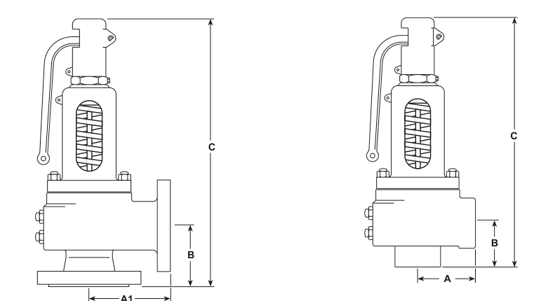
Dimensions, weights and orifice sizes (approximate) in inches and lbs
| Inlet size | Inlet connection | Outlet size | Outlet connection | Orifice | A (ins) | A1 (ins) | B (ins) | C (ins) | Weight (lbs) |
|---|---|---|---|---|---|---|---|---|---|
| 1½" | NPT | 2½" | NPT | J | 3.5 | - | 4.3 | 15.8 | 33 |
| 2" | NPT | 3" | NPT | K | 4.0 | - | 4.6 | 17.1 | 46 |
| 2½" | NPT | 4" | NPT | L | 4.6 | - | 5.5 | 18.5 | 66 |
| 3" | NPT | 4" | NPT | M | 5.1 | - | 5.6 | 24.3 | 93 |
| 1½" | ANSI 250 | 2½" | NPT | J | 3.5 | - | 4.3 | 15.8 | 38 |
| 2" | ANSI 250 | 2½" | NPT | J | 3.5 | - | 4.3 | 15.8 | 40 |
| 2" | ANSI 250 | 3" | NPT | K | 4.0 | - | 4.6 | 17.1 | 49 |
| 2½" | ANSI 250 | 3" | NPT | K | 4.0 | - | 4.6 | 17.1 | 51 |
| 2½" | ANSI 250 | 4" | NPT | L | 4.6 | - | 5.5 | 19.5 | 71 |
| 3" | ANSI 250 | 4" | NPT | L | 4.6 | - | 5.5 | 19.5 | 73 |
| 3" | ANSI 250 | 4" | NPT | M | 5.1 | - | 5.4 | 24.3 | 101 |
| 3" | ANSI 250 | 4" | ANSI 125 | L | - | 5.5 | 5.5 | 19.5 | 82 |
| 3" | ANSI 250 | 4" | ANSI 125 | M | - | 5.5 | 5.4 | 24.3 | 110 |
| 4" | ANSI 250 | 6" | ANSI 125 | N | - | 7.1 | 6.8 | 26.5 | 187 |
| 4" | ANSI 250 | 6" | ANSI 125 | P | - | 7.1 | 6.8 | 28.5 | 196 |
| 6" | ANSI 250 | 8" | ANSI 125 | Q | - | 9.3 | 9.3 | 34.5 | 355 |
| 6" | ANSI 250 | 8" | ANSI 125 | R | - | 10.0 | 10.9 | 43.9 | 595 |
Safety valve sizing information
For steam service, the required orifice area A (in²) is calculated from the relieving pressure P, the inlet temperature T and the required steam capacity, using the derated coefficient of discharge Kd = 0.955 and the steam superheat correction factor Ksh. Where P = relieving pressure in pounds per square inch absolute = set pressure (psi g) + overpressure + 14.7, with overpressure of 3% or 2 psi, whichever is greater; T = inlet temperature in °F absolute (°F plus 460); Ksh = steam superheat correction factor from Table 1. For organic fluid vaporizers and air/gas service the corresponding vapour capacity formulas apply, using average molecular weight M, gas/vapour flow constant C and compressibility factor Z.
| Total steam temperature °F | Ksh range across set pressures |
|---|---|
| 250 (saturated steam temperature) | 1.00 |
| 280 | 1.00 |
| 300 | 1.00 |
| 320 | 1.00 |
| 340 | 0.99 - 1.00 |
| 360 | 0.99 - 1.00 |
| 380 | 0.98 - 1.00 |
| 400 | 0.98 - 1.00 |
| 420 | 0.97 - 1.00 |
Sizing and selection should refer to the Spirax Sarco safety valve sizing guidance in the steam engineering tutorials.
Selection guide and ordering
| Element | Options |
|---|---|
| Series number | SV7 |
| Construction | 3 = cast iron |
| ASME section | V = ASME Code Section I; U = ASME Code Section VIII; blank = valve without code stamp |
| Size and connection | A = 1½" NPT x 2½" NPT; B = 2" NPT x 3" NPT; C = 2½" NPT x 4" NPT; D = 3" NPT x 4" NPT; E = 1½" ANSI 250 x 2½" NPT; F = 2" ANSI 250 x 2½" NPT; G = 2" ANSI 250 x 3" NPT; H = 2½" ANSI 250 x 3" NPT; I = 2½" ANSI 250 x 4" NPT; J = 3" ANSI 250 x 4" NPT; L = 3" ANSI 250 x 4" ANSI 125; N = 4" ANSI 250 x 6" ANSI 125; Q = 6" ANSI 250 x 8" ANSI 125 |
| Actual orifice area (sq. in.) | J = 1.374; K = 1.968; L = 3.054; M = 3.846; N = 4.633; P = 6.830; Q = 11.811; R = 17.123 |
| Set pressure | Specify set pressure from 5 psi g to 250 psi g |
How to order example: 1 off Spirax Sarco SV73-V-AJ-180 safety valve having a set pressure of 180 psi g.
Scope and safe use
This installation and maintenance fragment preserves the instructions for the SV73 from IM-S13-33, CTLS Issue 10. The source manual also covers the SV74; content that applies only to the SV74 — its pressure/temperature limits, dimension rows, materials rows and PED marking — is excluded from this SV73 page. Safe operation of the valve can only be guaranteed if it is properly installed, commissioned and maintained by a qualified person in compliance with the operating instructions. General installation and safety instructions for pipeline and plant construction, as well as the proper use of tools and safety equipment, must also be complied with.
1. Safety information
1.1 Intended use
- Referring to these Installation and Maintenance Instructions, the name-plate and the Technical Information Sheet, check that the product is suitable for the intended use/application.
- The SV73 safety valve body, bonnet and cap are manufactured in grey cast iron and, as such, the valve does not fall within the scope of the Pressure Equipment Directive. The SV73 therefore cannot be used on any installation within the EU.
- The SV73 has been specifically designed for use on steam, air and inert industrial gases.
- Check material suitability, pressure and temperature and their maximum and minimum values. If the maximum operating limits of the product are lower than those of the system in which it is being fitted, or if malfunction of the product could result in a dangerous overpressure or overtemperature occurrence, ensure a safety device is included in the system to prevent such over-limit situations.
- Determine the correct installation situation and direction of fluid flow. Spirax Sarco products are not intended to withstand external stresses induced by any system to which they are fitted; the installer is responsible for considering these stresses and taking adequate precautions to minimise them.
- Remove protective covers from all connections and protective film from name-plates before installation on steam or other high-temperature applications.
1.2-1.13 Access, hazards, permits and handling
Ensure safe access and, if necessary, a guarded working platform before attempting to work on the product; arrange suitable lifting gear where required. Provide adequate lighting, particularly for detailed or intricate work. Consider what is, or has been, in the pipeline — flammable materials, substances hazardous to health and extremes of temperature — and the surrounding environment, including explosion risk areas, lack of oxygen, dangerous gases, hot surfaces, fire hazard, excessive noise and moving machinery.
Consider the effect on the complete system of the work proposed: closing isolation valves or electrical isolation must not put another part of the system or any personnel at risk, and isolation valves must be turned on and off gradually to avoid system shocks. Ensure that any pressure is isolated and safely vented to atmospheric pressure; consider double isolation and do not assume the system has depressurised even when the pressure gauge indicates zero. Allow time for temperature to normalise after isolation to avoid danger of burns. Have suitable tools and consumables available and use only genuine replacement parts. Assess protective clothing needs and comply with the permit-to-work system. All work must be carried out or supervised by a suitably competent person.
1.13-1.17 Residual hazards and product-specific safety
In normal use the external surface of the product may be very hot. If used at the maximum permitted operating conditions, surface temperature may exceed 350 °C. The product should not be dismantled without first releasing the compression on the adjustment spring. If the valve is to be installed outdoors, the inlet neck and body of the valve must be insulated to reduce the effects of temperature variation. Unless otherwise stated, the product is recyclable and no ecological hazard is anticipated with its disposal providing due care is taken. When returning products to Spirax Sarco, provide written information on any hazards and the precautions to be taken.
1.18 Working safely with cast iron products on steam
Cast iron products are commonly found on steam and condensate systems. If installed correctly using good steam engineering practices, it is perfectly safe. However, because of its mechanical properties, it is less forgiving compared to other materials such as SG iron or carbon steel. Cast iron is a brittle material: if the product is dropped during installation and there is any risk of damage, the product should not be used unless it is fully inspected and pressure tested by the manufacturer. The good engineering practices that prevent waterhammer and ensure safe working conditions on a steam system must be followed.
2. General product information
2.1 Description
The SV7 series is a semi-nozzle, full-lift safety valve suitable for steam, air and other inert industrial gases. They are primarily intended for use on power boilers and unfired pressure vessels and comply with Section I and VIII of the ASME Boiler and Pressure Vessel Code. The SV73 has a grey cast iron body with stainless steel trim in orifice sizes 'J' to 'R'.
2.2 Standards, approvals and certification
The SV7 is designed in accordance with ASME Boiler and Pressure Vessel Codes Section I and Section VIII. The National Board of Boiler and Pressure Vessel Inspectors certifies design and capacities. Each valve may be stamped with the ASME 'UV' code symbol for Section VIII valves or the ASME 'V' code symbol for Section I valves. Seat tightness is in accordance with ASME/API STD 527-1992. A manufacturers' Typical Test Report is provided as standard for each valve, which includes the valve set and hydraulic test pressure; material certification in accordance with EN 10204 3.1 is also available on request.
2.3 Sizes and end connections
| Type | Inlet | Outlet |
|---|---|---|
| SV73 | 1½" x 2½" to 3" x 4", screwed NPT female | Screwed NPT female |
| SV73 | 1½" x 2½" to 3" x 4", flanged ASME 250 | Screwed NPT female |
| SV73 | 3" x 4" to 6" x 8", flanged ASME 250 | Flanged ASME 125 |
Note: Drain hole connection ½" NPT on all valve sizes.
2.4 Pressure/temperature limits
Please contact Spirax Sarco, when so required, for relevant details regarding the maximum allowable limits that the shell can withstand.
| Item | Value |
|---|---|
| Body design conditions | ANSI 250 |
| Set pressure range — maximum / minimum | 250 psi g / 5 psi g (minimum 15 psi g ASME code stamped) |
| Design temperature — maximum | 406 °F screwed inlet / 446 °F flanged inlet |
| Design temperature — minimum | -20 °F |
| Operating temperature — maximum | 406 °F screwed inlet / 446 °F flanged inlet |
| Overpressure | ASME I steam 3%; ASME VIII steam 10%; air/gas 10% |
| Blowdown limits | ASME I steam 2-6%; ASME VIII steam 7%; air/gas 7% |
| Derated coefficient of discharge | 0.955 steam; 0.955 air/gas |
| Maximum permitted backpressure | 10% of set pressure |
| Cold hydraulic test pressure | 600 psi g maximum inlet |
The product must not be used in the prohibited region of the pressure/temperature graph; A-B is the limit for valves with a flanged inlet and C-D is the limit for valves with a screwed inlet. See the technical information for the graph.
2.5 How to select and order
The SV73 is selected through the SV7 code: series SV7, construction 3 (cast iron), ASME section V (Section I), U (Section VIII) or blank (no code stamp), the size and connection letter, the orifice letter and the set pressure. Set pressures below 15 psi g are not ASME coded. How to order example: 1 off Spirax Sarco SV73-V-AJ safety valve having a set pressure of 180 psi g (12.5 bar g).
3-4. Supply and handling
The internal parts of the SV7 safety valve are precision machined and assembled to maintain perfect alignment. Rough handling may damage the seats or cause sufficient misalignment to incur leakage or erratic operation. Safety valves should be handled with care. Prior to installation they should remain in the packing provided by the supplier and be kept in a clean, dry, covered storage area and segregated from other valves, fittings and pipework.
5. Before fitting the valve
- Ensure that the pipework installation is suitable for the valve.
- Check that the details on the safety valve name-plate are compliant with the installation and process.
- Blow through the pipework to ensure that it is completely free of any foreign matter that may otherwise pass to the valve seat and cause damage, leading to seat leakage. Blowdown must be carried out before installing the safety valve.
- Remove all packaging and protective flange covers. Avoid getting any dirt or scale inside the valve before installation.
- Visually inspect the valve for any apparent damage. Ensure all wires and seals are intact.
- Ensure that the valve is set to the correct pressure.
6. Installation
The safety valve should always be fitted with the centre line of the spring housing vertically above the valve. The connection between the valve and the boiler or vessel shall have an area at least equal to the valve inlet. For ASME Section VIII valves, the valve should be connected to the vessel in the vapour space above any contained liquid, or to the piping connected to the vapour space in the vessel which is to be protected.
Note: Stop valves are not permitted between vessel and safety/relief valve and the discharge to atmosphere, except per ASME Section VIII UG-135(e).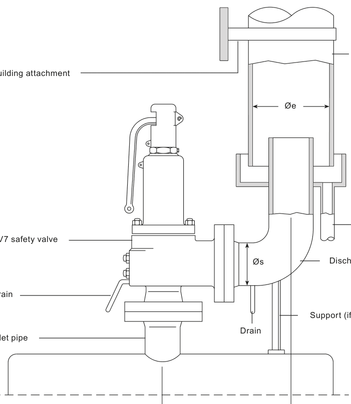
7. Damage prevention
Excessive pressure loss at the inlet of a safety valve when it operates will cause extremely rapid opening and closing of the valve, observed as chattering or hammering. This may result in reduced capacity as well as damage to seating faces and other parts of the valve. When normal pressure is restored it is possible that the valve will leak.
- Pressure loss at inlet should be no more than 3% of the pressure differential between set pressure and superimposed back pressure when discharging.
- The valve should be fitted 8-10 pipe diameters downstream of converging or diverging fittings or bends.
- Inlet branches should follow the documented arrangements: the inlet area should be approximately twice that of the branch, and the bend radius not less than the inlet diameter.
8. Commissioning
- Once the valve has been fitted, check that there are no leaks from either the inlet or the outlet connections.
- Test the set pressure of the valve by raising the system pressure. Ensure that the valve operates correctly at its specified set pressure as indicated on the name-plate.
- Check that the overpressure is limited to 3% of the safety valve set pressure (ASME I applications) or 10% (ASME VIII applications).
- Reduce the system pressure to the normal operating pressure and check that the safety valve reseats.
9. Testing during use
Note: Use suitable protection against excess heat and noise when testing safety valves.
It is recommended that the safety valve is tested for correct operation on a regular basis as part of a documented and controlled procedure. The frequency of testing is dependent on the application and system conditions, and an appropriate test interval must be decided by the user or relevant insurance company. The SV7 can be operated manually by means of the test lever when the system pressure is at least 85% of the set pressure, or the system pressure may be carefully increased until the valve operates.
10. Maintenance
All safety valves should receive planned maintenance. SV7 safety valves are 100% tested and then sealed to prevent unauthorised adjustment or repair. Valves should be inspected regularly to assure continued safe operation and long service life: a visual inspection is recommended at two month intervals while in service, followed by a complete pressure test at least once a year.
Any valve that fails to open within 103% (ASME I) or 110% (ASME VIII) of the name-plate set pressure, or fails to open or close properly, must be removed for replacement or repair. Never attempt to stop leakage by compressing the spring or gagging the valve. For repair and resetting of ASME Code Section I and VIII stamped valves, ASME authorised and approved safety valve repair facilities must be used.