
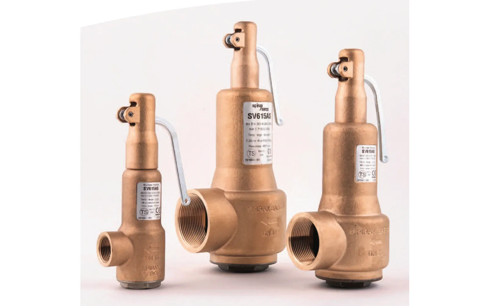
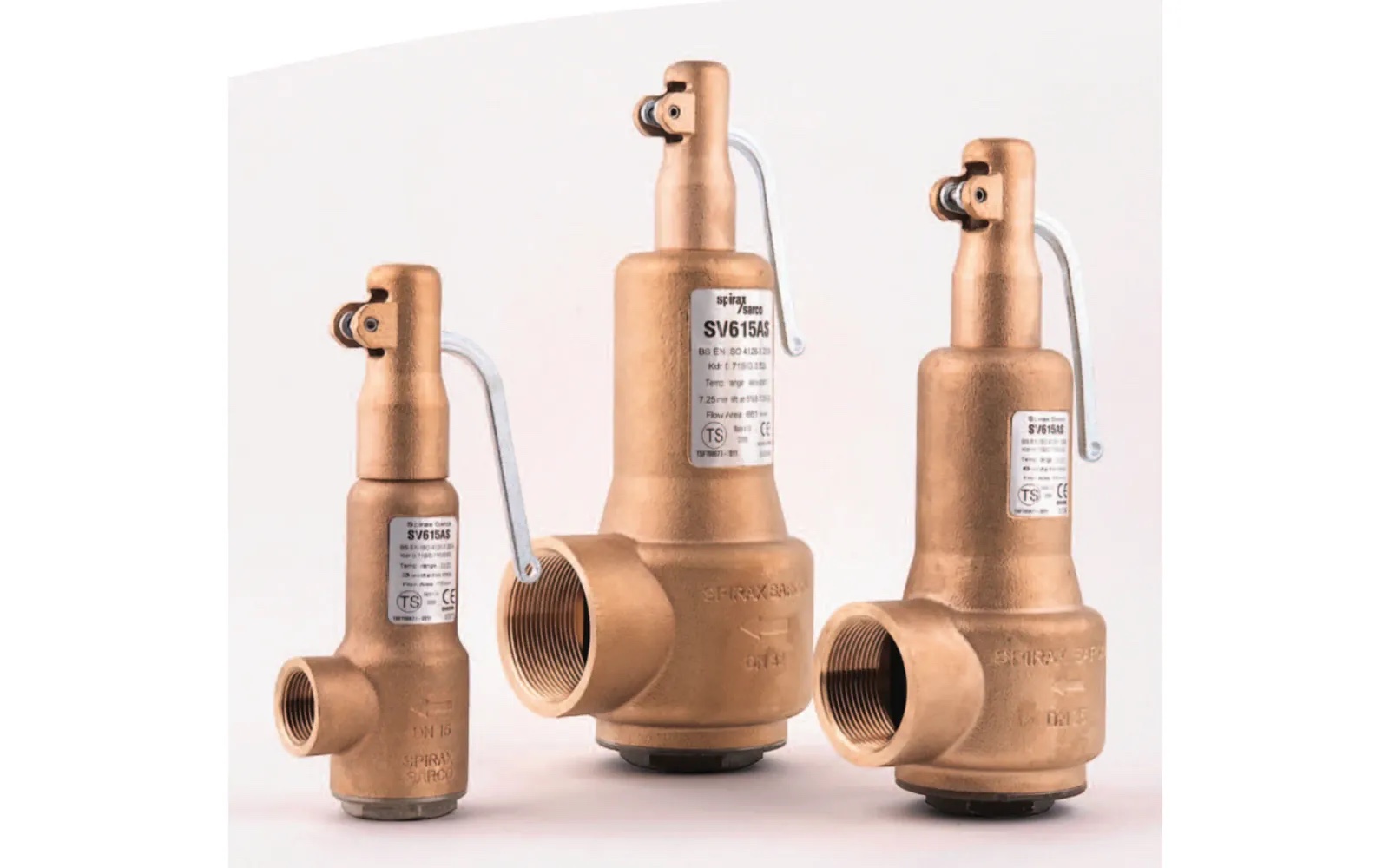
Compact overpressure protection for steam, gas and liquid duties
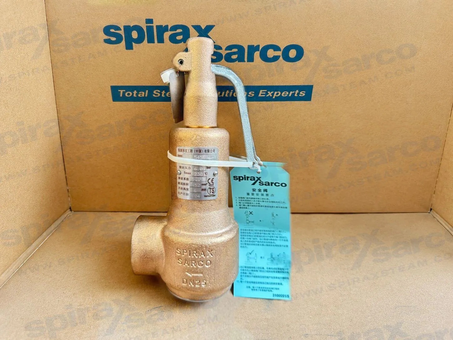
The Spirax Sarco SV615 is a full-lift, full-nozzle bronze safety valve for steam, air, inert industrial gases and non-hazardous liquids. It covers DN15 to DN50 screwed installations, with a sanitary clamp inlet option on DN15 to DN25.
Closed-bonnet versions use either a lifting lever or a gas-tight cap. Metal, Nitrile, EPDM and Viton seat configurations support different media and temperature requirements; soft-seat inserts are not suitable for steam.
Typical applications
- Steam and hot-water boiler systems
- Pressure vessels, receivers and generators
- Air compressors and autoclaves
- Downstream protection for pressure-reducing valves
- General pressure-relief duties
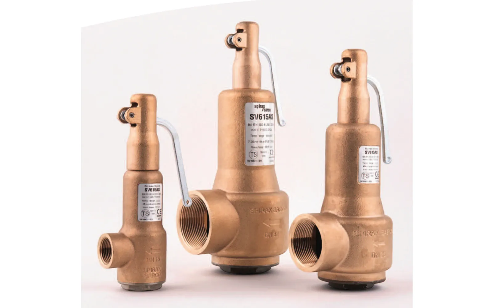
Selection snapshot
| Size range | DN15-DN50 |
|---|---|
| Body design | PN25 |
| Set pressure | 0.3-18 bar g for 1/2 to 1 1/4 inch; 0.3-14 bar g for 1 1/2 and 2 inch |
| Connections | BSP or NPT female; 1-inch sanitary clamp inlet on DN15-DN25 |
| Standards | EN ISO 4126:2004; ASME/API STD 527 Revision 2002 seat tightness |
Technical information
Spirax Sarco SV615 safety valve description
The SV615 safety valve, with a full-lift, full-nozzle design, is suitable for steam, air, inert industrial gas and non-hazardous liquid service.
SV615 safety valve applications
Typical duties include steam or hot-water boilers, generators, vessels, receivers, air compressors, autoclaves, downstream protection for pressure-reducing valves and general pressure-relief applications.
Available types
Sizes DN15 to DN50 have a bronze body, female screwed connections and a stainless-steel nozzle. DN15, DN20 and DN25 can use a 1-inch sanitary clamp inlet. Closed-bonnet variants are available with a lifting lever or a gas-tight closed cap. Optional soft seals are Nitrile, EPDM or Viton. Electroless nickel plating and a mechanically fastened stainless-steel nameplate are options.
Standards, approvals and certification
The SV615 safety valve complies with EN ISO 4126:2004 and the European Pressure Equipment Directive 2014/68/EU. Seat tightness complies with ASME/API STD 527, Revision 2002. A manufacturer's Typical Test Report covering set pressure and hydraulic test pressure is supplied as standard. EN 10204 3.1 material certification is available on request.
Sizes and end connections
| Connection | Available form |
|---|---|
| Sizes | DN15, DN20, DN25, DN32, DN40 and DN50 |
| Inlet | BSP T Rp (ISO 7-1), BSP to BS 21, or NPT female |
| Sanitary inlet | 1-inch clamp compatible, DN15-DN25 only; BS 4825 / ISO 2852 / DIN 32676 |
| Outlet | BSP parallel or NPT female |
SV615 pressure and temperature limits
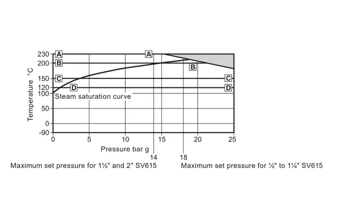
| Body design condition | PN25 |
|---|---|
| Set pressure, 1/2 to 1 1/4 inch | 0.3 to 18 bar g |
| Set pressure, 1 1/2 and 2 inch | 0.3 to 14 bar g |
| Metal seat | -90 °C to +230 °C |
| Nitrile seat | -30 °C to +120 °C |
| EPDM seat | -50 °C to +150 °C |
| Viton seat | -20 °C to +200 °C |
| Overpressure | Steam 5%; gas 10%; liquid 10% |
| Blowdown limit | Steam/gas 10%; liquid 20% |
| Derated discharge coefficient | Steam/gas 0.71; liquid 0.52 |
| Maximum permitted backpressure | 10% of set pressure |
| Cold hydraulic test pressure | 37.5 bar g |
Important: Soft-seat inserts are not suitable for steam applications. Local regulations may restrict use below the limits shown.
The minimum set pressure is 0.3 bar g.
SV615 construction and materials
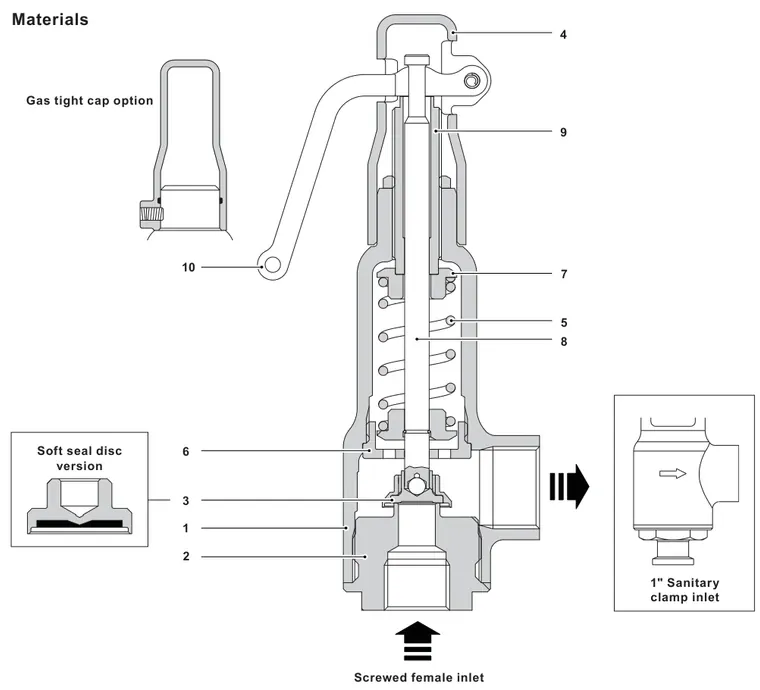
| No. | Part | Material | Specification |
|---|---|---|---|
| 1 | Body | Bronze | BS EN 1982 CC491KM |
| 2 | Nozzle, DN15-DN20 | Stainless steel | BS 970 431 S29 |
| 2 | Nozzle, DN25-DN50 | Stainless steel | BS 3146 Pt2 Gr. ANC2 |
| 2 | Nozzle, sanitary | Stainless steel | ASTM A276 316L |
| 3 | Disc | Stainless steel | ASTM A276 316L |
| 4 | Lever housing | Bronze | BS EN 1982 CC491KM |
| 5 | Spring | Chrome-vanadium alloy steel | BS 2803 735 A50 HS |
| 6 | Stem guide | Brass | BS 2872 CZ 121 |
| 7 | Spring end plate | Brass | BS EN 12165 CW617N |
| 8 | Stem | Stainless steel | BS 970 431 S29 |
| 9 | Adjustment screw | Brass | BS 2874 CZ 121 |
| 10 | Lever | SG iron | Zinc plated |
| 11 | Pivot pin | Stainless steel | AISI 304 |
| 12 | Circlip | Stainless steel | BS 2056 316 S42 |
| 13 | Adjuster lock-nut | Brass | BS 2872 CZ 121 |
| 14 | Soft-seal disc | 316 stainless steel with Nitrile, EPDM or Viton F81 insert | ASTM A276 316 |
| 15 | Sealed cap | Bronze | BS EN 1982 CC491KM |
| 16 | Cap seal | Nitrile | - |
| 17 | Skirt | Brass | BS 2874 CZ 121 |
| 18 | Grub screw | Steel | - |
| 19 | Ball | Stainless steel | - |
SV615 capacity data
Published capacity tables cover dry saturated steam, air at 0 °C and 1.013 bar a, water at 20 °C, and hot water at or above 100 °C. The applicable derated discharge coefficients are 0.71 for steam/gas and 0.52 for liquid. Final sizing must use the complete Issue 20 capacity tables and the actual required relieving duty.
| Valve DN inlet/outlet | 15/20 | 20/32 | 25/40 | 32/50 | 40/65 | 50/80 |
|---|---|---|---|---|---|---|
| Flow area, mm2 | 113 | 314 | 452 | 661 | 1 075 | 1 662 |
SV615 dimensions and approximate weights
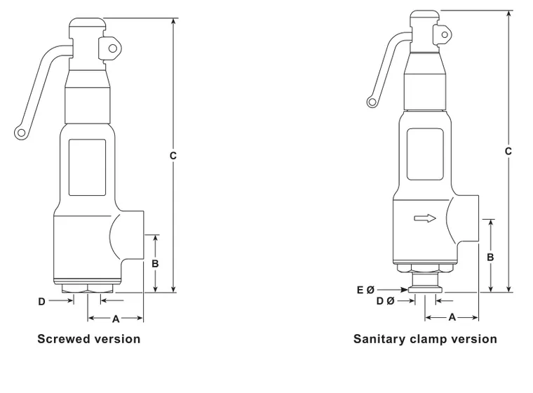
| Version | Size | Inlet | Outlet | A | B | C | Flow D | kg |
|---|---|---|---|---|---|---|---|---|
| Screwed | DN15 | 1/2 | 3/4 | 40 | 40 | 194 | 12 | 1.3 |
| Screwed | DN20 | 3/4 | 1 1/4 | 55 | 44 | 229 | 20 | 2.4 |
| Screwed | DN25 | 1 | 1 1/2 | 60 | 48 | 242 | 24 | 2.9 |
| Screwed | DN32 | 1 1/4 | 2 | 70 | 58 | 279 | 29 | 4.2 |
| Screwed | DN40 | 1 1/2 | 2 1/2 | 81 | 67 | 365 | 37 | 8.8 |
| Screwed | DN50 | 2 | 3 | 96 | 80 | 420 | 46 | 13.0 |
| Sanitary | DN15 | 1 | 3/4 | 40 | 55 | 209 | 12 | 1.4 |
| Sanitary | DN20 | 1 | 1 1/4 | 55 | 60 | 245 | 20 | 2.6 |
| Sanitary | DN25 | 1 | 1 1/2 | 60 | 64 | 258 | 24 | 3.1 |
Spirax Sarco SV615 selection guide
| Element | Code and option |
|---|---|
| Model | SV615 |
| Configuration | A = closed bonnet/easing lever; B = closed bonnet/sealed cap |
| Seal | S = stainless steel; N = Nitrile; E = EPDM; V = Viton |
| Finish | P = electroless nickel plated; Q = ELNP with stainless-steel nameplate |
| Connections | BSPF x BSPF; NPTF x NPTF; clamp x BSPF |
Example: SV615AN, DN15, BSPF x BSPF, set at 6 bar g.
For complete installation and safety requirements, refer to IM-P316-03.
Installation and maintenance
Installation and Maintenance Guide
Safe operation depends on correct installation, commissioning and maintenance by qualified personnel in accordance with these instructions and applicable plant safety procedures.
1. Safety information
Confirm the valve is suitable for the fluid, material, pressure and temperature conditions. Determine the correct installation position and flow direction, and prevent external pipe stresses from acting on the valve.
- Provide safe access, adequate lighting and suitable lifting equipment where required. Equipment above 20 kg should be handled with suitable lifting assistance.
- Identify hazardous fluids, gases, temperatures, pressure and environmental risks before work begins.
- Isolate and safely vent pressure; do not assume zero gauge pressure means the system is depressurised.
- Allow hot equipment to cool and use appropriate protective clothing, tools and genuine replacement parts.
- Work must be performed or supervised by competent personnel under the site's permit-to-work system.
- Protect non-self-draining equipment against freezing where necessary.
Product-specific warning: Do not dismantle the valve before releasing spring compression. The SV615AV and SV615BV soft-seal variants contain Viton/FPM. Material exposed near 315 °C may decompose and form hydrofluoric acid. Avoid contact with dust or fumes and follow current disposal guidance.
2. Spirax Sarco SV615 product information
The SV615 is a full-lift, full-nozzle safety valve for steam, air, inert industrial gases and non-hazardous liquids. It is available in DN15-DN50 with a bronze body and stainless-steel nozzle.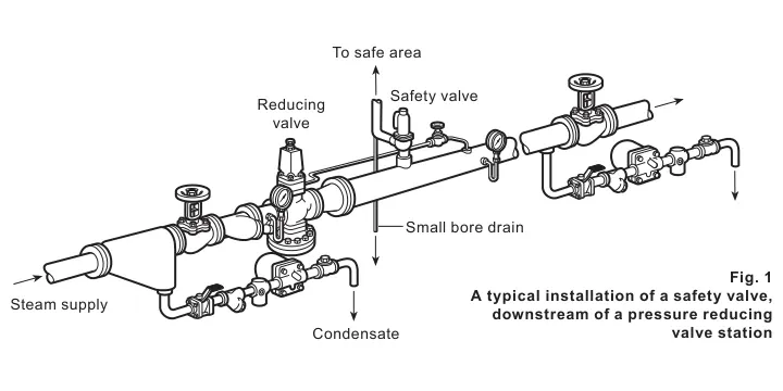
| Sizes | DN15, DN20, DN25, DN32, DN40, DN50 |
|---|---|
| Inlet | BSP female to BS 21, NPT female, or 1-inch sanitary clamp for DN15-DN25 to BS 4825 / ISO 2852 / DIN 32676 |
| Outlet | BSP parallel or NPT female |
| Configuration | Closed bonnet with lifting lever or sealed cap |
| Soft seals | Nitrile for air to 120 °C; EPDM for water; Viton for air to 200 °C |
The SV615 complies with EN ISO 4126:2004. Seat tightness complies with ASME/API STD 527 Revision 2002. A Typical Test Report is standard, and EN 10204 3.1 material certification is available on request.
Pressure and temperature reference
| Body design | PN25 |
|---|---|
| Set pressure | 0.3 bar g minimum; 18 bar g maximum for 1/2 to 1 1/4 inch; 14 bar g maximum for 1 1/2 and 2 inch |
| Metal seat | -90 °C to +230 °C |
| Nitrile | -30 °C to +120 °C |
| EPDM | -50 °C to +150 °C |
| Viton | -20 °C to +200 °C |
| Liquid blowdown limit | 20% |
| Cold hydraulic test pressure | 37.5 bar g |
Principal material specifications
Principal specifications include BS EN 1982 CC491KM bronze, BS 970 S29 stainless steel, BS 3146 ANC2 stainless steel, ASTM A276 stainless steel, BS 2803 A50 spring steel, BS 2872 and BS 2874 brass, BS EN 12165 CW617N brass, and BS 2056 S42 stainless steel. The Viton soft-seal insert designation is F81.
3. Supply
The valve is normally supplied set to the required pressure and sealed. Setting must only be performed by authorised, competent personnel.
4. Handling
- Transport the valve upright.
- Do not drop it or subject it to sudden shock or heavy impact.
- Keep it in the supplier's packaging until required.
- Never carry a safety valve by its lifting lever.
5. Before fitting the SV615
- Confirm the proposed installation follows the system arrangement requirements.
- Blow through the pipework before installing the valve to remove foreign matter that could damage the seat.
- Confirm the valve has the correct set pressure.
6. Installing the SV615 safety valve
Caution: Prevent liquid jointing compounds and thread sealants from contaminating internal seating faces.
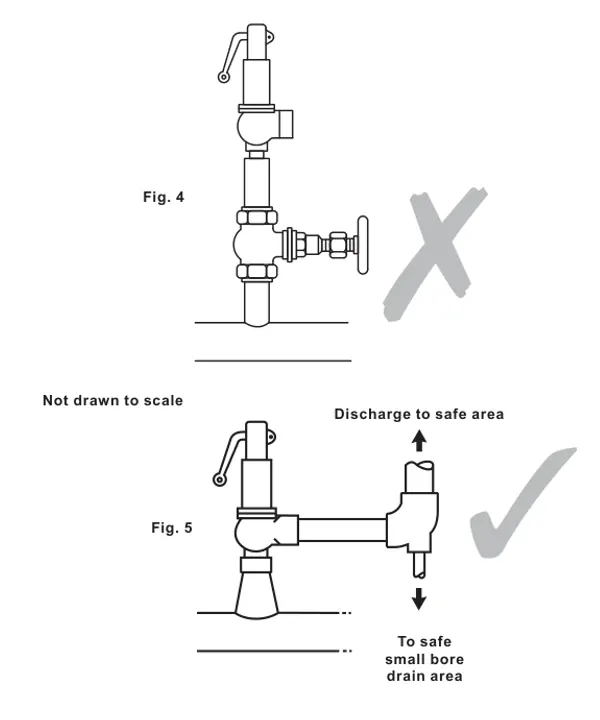
- Mount the valve vertically upright with its main axis vertical.
- Use the shortest practical connection to the pipework or vessel.
- Do not install an intervening valve or fitting that could isolate the safety valve.
- The inlet connection must not be smaller than the safety valve inlet.
- Size the discharge system so built-up backpressure does not exceed 10% of gauge set pressure.
- Route discharge to a safe point and support the discharge pipe independently.
- Provide a drain at the lowest point where discharge pipework rises.
- Give each safety valve its own unrestricted discharge pipe.
- Do not lag the valve. Protect personnel against sudden discharge, heat and noise.
- Use a wrench on the inlet hexagon; do not grip the body or apply excessive leverage.
7. Damage prevention
Excessive inlet pressure loss can cause rapid opening and closing, reduced capacity, seat damage and leakage. Install the valve 8-10 pipe diameters downstream of bends or converging/diverging fittings. Use a branch radius not less than the inlet diameter, or an inlet area approximately twice the valve inlet area.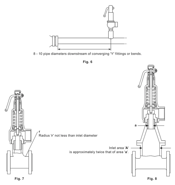
8. Commissioning
- Check inlet and outlet connections for leakage.
- Raise system pressure and confirm the valve operates at the correct set pressure.
- Reduce pressure to normal operating pressure and confirm the valve reseats.
9. Testing during use
Include operational testing in a documented and controlled procedure. The test interval depends on application and system conditions and should be agreed by the user or relevant insurer.
Lever test: Do not operate the lever unless system pressure is at least 85% of set pressure. Use hand force only; never use a tool or extension.
10. SV615 setting guidelines
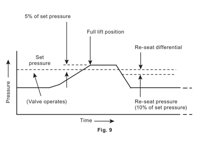
Setting must be performed only by authorised, competent personnel. Adequate differential is required between maximum system operating pressure and set pressure so the valve can reseat. The SV615 achieves rated capacity at 5% overpressure on steam and 10% on air.
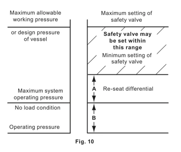
Under the BS 5500 setting guidance cited by the source document, the maximum set pressure is the safe working pressure of the protected plant and rated capacity must be achieved with no more than 10% overpressure. The setting-range diagram uses A = 10% of set pressure, with a 0.3 bar minimum, and B = normal system pressure variation.
For metal-seated valves in steam service, Spirax Sarco recommends cold setting on a test rig at 3% above the required set pressure. This does not apply when setting on steam. Unset valves supplied to approved agents must be tagged with the final set pressure. A selection example is SV615AN, DN15, BSPF x BSPF, set at 6 bar g.
11. SV615 safety valve maintenance
All safety valves require planned maintenance. Read the safety information before work. Spirax Sarco recommends periodic return to an authorised local agent for overhaul, testing, resetting and sealing in accordance with industry procedures.