
SV604
SV604 Flanged Full-Lift Safety Valve
SV604 is a carbon-steel full-lift flanged safety valve for steam, inert industrial gas and water, with DN20–DN150 inlet sizes, documented PN40 or ASME 300 inlet connections, and a -10 °C to 400 °C temperature envelope subject to the technical limits.
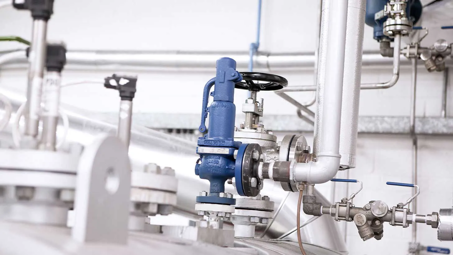
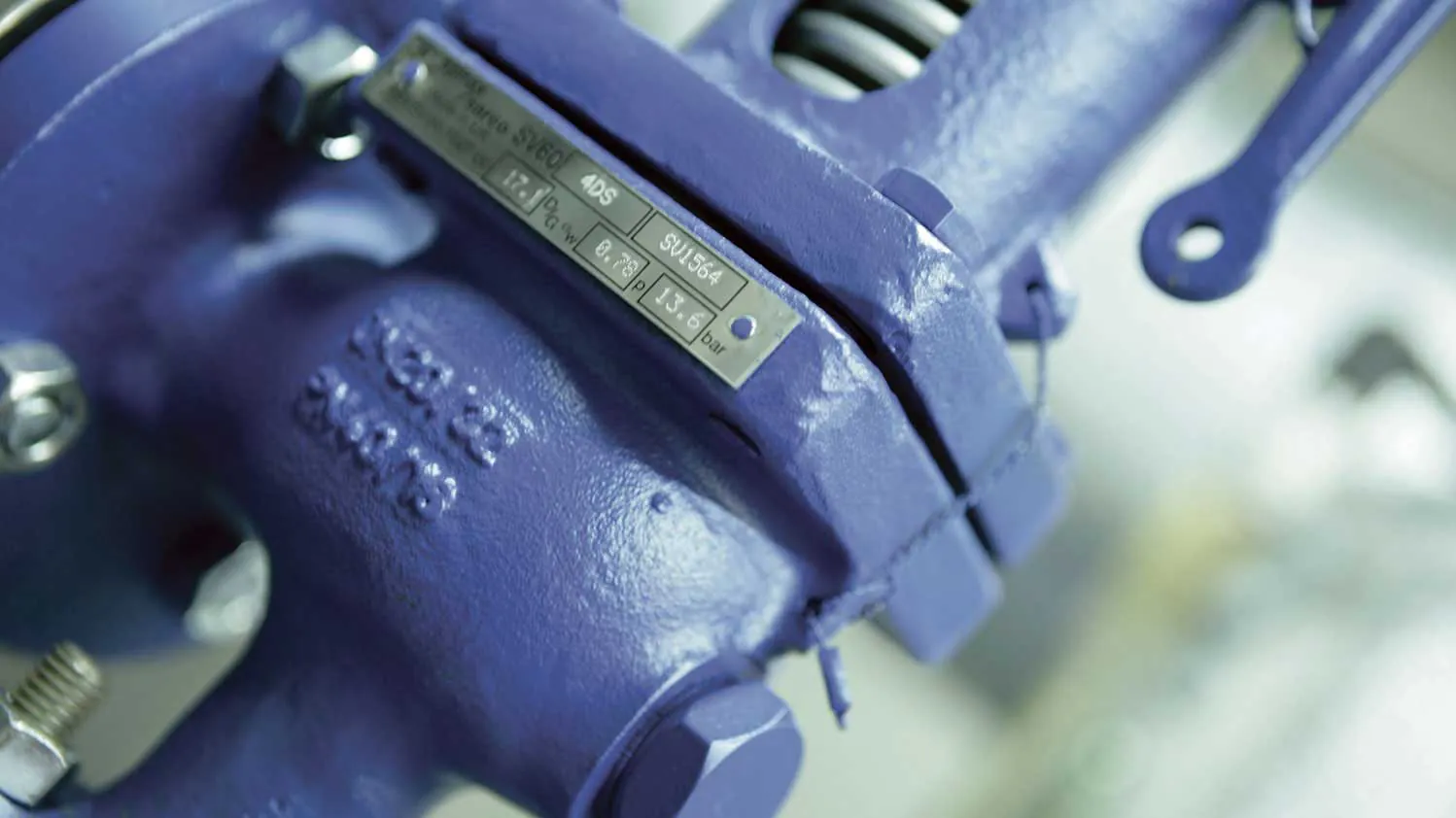
SV604 full-lift flanged safety valve
The Spirax Sarco SV604 is a carbon-steel full-lift flanged safety valve for protecting pressure equipment and process systems from overpressure. It is documented for steam, inert industrial gas and water service, with inlet sizes from DN20 to DN150 and flanged connection arrangements for PN40 or ASME 300 inlet service. The outlet is selected as PN16 for the PN route or ASME 150 for the ASME route. This combination gives plant designers a clear route from the protected-equipment limit to the valve size, set pressure, discharge arrangement and certification required for the duty.
SV604 is a model-level safety valve selection rather than a generic relief-device description. The applicable pressure/temperature graph, set-pressure range, relieving medium, overpressure allowance, backpressure and bonnet or spring configuration must all be checked together. The figures and detailed tables below are therefore part of the engineering selection record, not a substitute for sizing the complete installation.
Product role and application
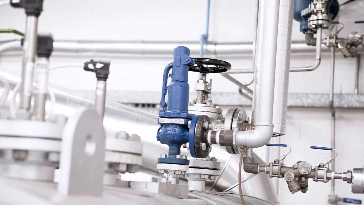
A full-lift safety valve opens rapidly when the protected system reaches its set pressure, providing the relieving area needed to control an overpressure event. SV604 is intended for duties such as steam boilers, steam and utility pipelines, pressure vessels, compressors, receivers and general process equipment. It can also be considered for inert industrial gas and water duties when the fluid, temperature, pressure and discharge arrangement have been checked against the data sheet.
For a steam system, the safety valve is commonly installed at the protected vessel or in a suitable steam line, including downstream of a pressure-reducing valve station where a regulator failure could expose downstream equipment to excessive pressure. For a Spirax Sarco SV604 selection, the valve must discharge to a safe location. A discharge pipe that is too small, poorly supported or exposed to excessive backpressure can change the relieving behaviour and impose damaging loads on the valve, so the complete piping layout is part of the selection.
Other media are not automatically covered by the words “water” or “gas”. Chemical compatibility, phase behaviour, contamination risk, temperature excursions and the applicable local rules must be reviewed with the manufacturer where the service is outside the stated range. The model should not be selected solely from the nominal pipe size or from a maximum pressure number.
Carbon-steel construction and configuration choices
The SV604 body and bonnet are carbon steel, with stainless-steel working components specified by size and component. The documented construction includes a stainless-steel seat, hardened stainless-steel disc options, a stainless-steel stem and skirt, and a spring selected for the pressure and temperature duty. This construction provides a robust flanged pressure boundary while leaving the set-pressure and configuration decision visible to the engineer responsible for the installation.
The ordering guide identifies closed-bonnet/easing-lever, closed-bonnet/sealed-cap, closed-bonnet/packed-lever and open-bonnet/easing-lever configurations. The packed lever is limited to DN20–DN100. A tungsten-alloy spring is required in the high-temperature region identified by the technical data and is available with the open-bonnet configuration. Open-bonnet valves are recommended for steam-boiler applications. The correct configuration therefore depends on the service, the temperature envelope, the need for manual testing and the safety of the discharge environment.
Each valve is supplied with a manufacturer’s Typical Test Report containing the set and hydraulic test pressure. Material certification to EN 10204 3.1 is available on request. The product documentation also records CE/PED and pressure-equipment-category information, seat-tightness testing to ASME/API Standard 527-1992, the applicable TÜV approvals and Lloyd’s Register type approval. The exact certificate and marking requirements still need to be confirmed for the destination market and the specified valve.
Pressure, temperature and relieving conditions
The SV604 technical sheet gives a minimum set pressure of 0.2 bar g, a maximum temperature of 400 °C and a minimum temperature of -10 °C. These are boundary values within the documented selection envelope, not a blanket permission to combine the maximum temperature with every pressure, size, connection or spring. The PN40 inlet graph identifies a region where the product must not be used and a region where a tungsten-alloy spring is required. The graph must be read with the selected set pressure and the actual fluid.
For PN40 SV604 configurations, the maximum set-pressure entry varies with the inlet/outlet size pair and with saturated steam, air or water. The technical tables show the corresponding limits and capacity data. Steam rated capacity is calculated at 5% overpressure. The stated overpressure for liquids and gas is 10%; the blowdown limit is 10% for steam and gas and 20% for liquids. Superimposed backpressure is limited to 10% of set pressure. These relationships are important because a valve that is correctly sized for one relieving medium or backpressure condition cannot be assumed to have the same duty for another.
Capacity selection requires the required relieving load, set pressure, inlet and outlet size, fluid state, temperature, allowable overpressure and backpressure. The technical information section provides the dry saturated steam, air and water tables, plus the flow-area and coefficient data used with the documented calculation method. The maximum inlet cold hydraulic test pressure is 60 bar g; it is a test boundary and should not be treated as the normal operating pressure.
Installation and system integration
Install the valve with its main axis vertical and the centre line of the spring housing vertically above the valve. The inlet connection should be as short as practicable and no smaller than the valve inlet. There must be no intervening valve or fitting that could isolate the safety device from the protected system. The outlet pipe should be at least as large as the valve outlet, use suitable long-radius fittings, and discharge to a location where hot, pressurised fluid and noise cannot injure people or damage equipment.
The discharge pipe needs independent support so its weight and thermal movement do not load the valve. Each safety valve should have its own unrestricted discharge pipe. Where condensate can collect, the body drain connection should be routed to a safe drain. On steam service, a small-bore drain is required at a suitable low point when the outlet rises. Body lagging should be limited as instructed in the installation guide, and the surface must be treated as hot during operation.
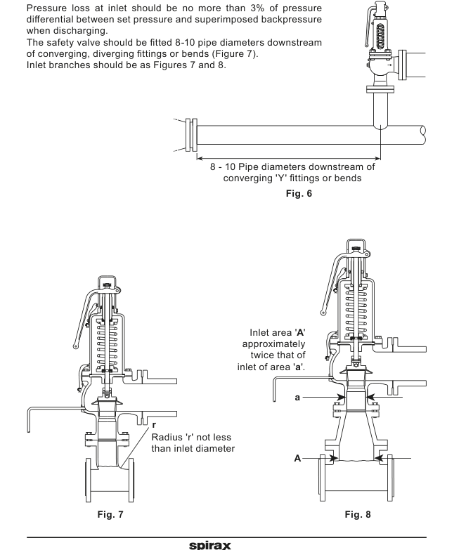
Inlet pressure loss is a key damage-prevention check. The installation guide limits inlet pressure loss to no more than 3% of the pressure differential between set pressure and superimposed backpressure while discharging, and recommends positioning the valve 8–10 pipe diameters downstream of converging, diverging fittings or bends. Chattering or hammering can reduce capacity, damage seating faces and leave the valve leaking after the system returns to normal pressure.
Commissioning, testing and maintenance
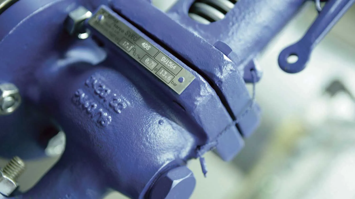
Before fitting, confirm the name-plate information, set pressure, fluid, material suitability and installation direction. Blow through the pipework before installation so foreign matter cannot damage the seat. Remove transport protection and easing-lever restraints only after the installation is ready. Work on the valve requires competent, trained personnel, suitable isolation and safe venting; the internal spring must be released before dismantling.
During commissioning, check the inlet and outlet connections for leaks, raise system pressure in a controlled manner, verify operation at the required set pressure and confirm the applicable overpressure limit. Reduce pressure to the normal operating condition and check that the valve reseats. Testing should form part of a documented procedure at least every 12 months unless the application, system conditions or responsible authority require a different interval. An easing lever must only be operated by hand when system pressure is at least 85% of set pressure; tools or extensions must not be used.
Planned maintenance is essential for a safety device. The installation guide recommends internal inspection no later than five years, or at an interval agreed with the insurance company, with overhaul, testing, resetting and sealing carried out by the manufacturer or an approved specialist. Disc and skirt assemblies are non-serviceable. Do not repair or rectify them in the field; damaged assemblies must be replaced or handled by an approved repair specialist. Heat, stored pressure, discharge noise and any process contamination must be controlled before inspection or removal.
How to select an SV604
Define the protected equipment, design pressure, normal operating pressure, relieving medium, temperature range and required relieving load.
Choose the inlet/outlet size pair from the documented DN20–DN150 range and confirm the flange standards and pressure route.
Set the valve within the protected equipment limit while leaving enough operating-pressure margin for stable reseating.
Check the SV604 PN40 pressure/temperature graph, overpressure, blowdown and backpressure limits for the actual service.
Specify bonnet, cap, easing lever and spring configuration, including the open-bonnet requirement for a tungsten-alloy spring.
Confirm discharge piping, drains, supports, certification, local approvals and the required test documentation before ordering.
Use the safety valve range as the category-level route when the protected-equipment duty or connection requirement indicates that a different product family should be evaluated. For a Spirax Sarco SV604 enquiry, provide the exact size, connection, set pressure, fluid, temperature, relieving load and bonnet/spring configuration so the selection can be checked against the official technical and installation documents.
Documented information for the project file
The technical information section that follows carries the model boundaries, pressure/temperature limits, capacity tables, material schedule, dimensions and selection guide from TI-S13-27, CMGT Issue 19. The installation section carries the safety information, handling, fitting, damage-prevention, commissioning, testing, setting and maintenance requirements from IM-P317-01, CTLS Issue 13. Together they give the engineer a traceable starting point; final sizing, conformity and installation approval remain responsibilities of the competent designer and installer.
Scope of this technical information
This fragment preserves the SV604-relevant technical information from TI-S13-27, CMGT Issue 19. The source data sheet describes the wider SV60 family, but this page retains only the SV604 carbon-steel full-lift flanged route and does not use other model variants as specifications for this product.
Product description and approvals
SV604 is suitable for steam, inert industrial gas and water services. Other media require confirmation of suitability. Applications include steam boilers, pipelines, pressure vessels, compressors, receivers and general process industry duties. The valve carries the CE mark and complies with the stated PED Category 4 Group 2 gas requirements. SV604 approval is listed to AD-Merkblatt A2, AD-Merkblatt A4, TRD 421, Vd TÜV 100 and 100/4, with Lloyd’s Register type approval certificate 01/00125 (E2). Seat tightness is to ASME/API Standard 527-1992.
A manufacturer’s Typical Test Report is supplied as standard and includes valve set and hydraulic test pressure. EN 10204 3.1 material certification is available on request.
Sizes and end connections
SV604 inlet and outlet connection routes | ||
Inlet connection | Outlet connection | Documented standard |
|---|---|---|
PN40 | PN16 | PN flanges to EN 1092 |
ASME 300 | ASME 150 | ASME flanges to EN 1759-1 |
Inlet sizes are DN20, DN25, DN32, DN40, DN50, DN65, DN80, DN100, DN125 and DN150. Select the inlet/outlet size pair and connection route together; the detailed limits below are not a general rating for every possible combination.
Pressure and temperature limits
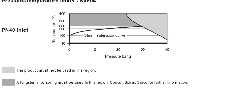
SV604 body design conditions and performance limits | |
Condition | Value or rule |
|---|---|
Body design route | PN40 inlet |
Minimum set pressure | 0.2 bar g |
Maximum temperature | 400 °C |
Minimum temperature | -10 °C |
Steam overpressure | 5% |
Liquids and gas overpressure | 10% |
Steam and gas blowdown limit | 10% |
Liquids blowdown limit | 20% |
Backpressure limit | 10% of set pressure |
Maximum inlet cold hydraulic test pressure | 60 bar g |
SV604 PN40 body design conditions and maximum set pressure | |||
Size inlet × outlet | Saturated steam (bar g) | Air (bar g) | Water (bar g) |
|---|---|---|---|
DN20 × DN32 | 29 | 40 | 40 |
DN25 × DN40 | 29 | 40 | 40 |
DN32 × DN50 | 29 | 40 | 40 |
DN40 × DN65 | 29 | 40 | 40 |
DN50 × DN80 | 29 | 40 | 40 |
DN65 × DN100 | 29 | 32 | 32 |
DN80 × DN125 | 29 | 32 | 32 |
DN100 × DN150 | 25 | 25 | 25 |
DN125 × DN200 | 20 | 20 | 20 |
DN150 × DN250 | 16 | 16 | 16 |
The body-design table is a maximum set-pressure reference and must be read with the graph, selected service and actual set pressure. The source sheet also includes a family connection row for other inlet pressure classes; those rows are outside the single-model SV604 route and are not used here.
Flow-area reference data
Orifice, flow area and water coefficient reference | ||||||||||
Valve size DN in/out | DN20 x DN32 | DN25 x DN40 | DN32 x DN50 | DN40 x DN65 | DN50 x DN80 | DN65 x DN100 | DN80 x DN125 | DN100 x DN150 | DN125 x DN200 | DN150 x DN250 |
|---|---|---|---|---|---|---|---|---|---|---|
Orifice (mm) | 17.0 | 23.8 | 30.6 | 38.0 | 50.1 | 59.0 | 73.0 | 91.0 | 105 | 125 |
Flow area (mm²) | 230 | 445 | 740 | 1 140 | 1 979 | 2 734 | 4 185 | 6 504 | 8 659 | 12 272 |
αw / αw (P > 4 bar) | 0.50 / 0.56 | 0.50 / 0.62 | 0.50 / 0.76 | 0.50 / 0.68 | 0.50 / 0.64 | 0.50 / 0.71 | 0.50 / 0.66 | 0.50 / 0.70 | 0.50 / 0.72 | 0.50 / 0.73 |
The source data sheet labels the following capacity tables as SV60 data and calculates steam capacity in accordance with EN ISO 4126. They are retained for the SV604 size range, subject to the SV604 connection and pressure/temperature limits. Capacities are not a substitute for a relieving-duty calculation.
Dry saturated steam capacity
Dry saturated steam capacity at 5% overpressure (kg/h) | ||||||||||
Set pressure (bar g) | DN20 x DN32 | DN25 x DN40 | DN32 x DN50 | DN40 x DN65 | DN50 x DN80 | DN65 x DN100 | DN80 x DN125 | DN100 x DN150 | DN125 x DN200 | DN150 x DN250 |
|---|---|---|---|---|---|---|---|---|---|---|
0.5 | 121 | 254 | 378 | 494 | 825 | 1279 | 1779 | 2876 | 4050 | 5844 |
1.0 | 180 | 379 | 571 | 763 | 1235 | 1893 | 2660 | 4355 | 5994 | 8635 |
1.5 | 238 | 504 | 765 | 1034 | 1654 | 2556 | 3557 | 5805 | 7974 | 11475 |
2.0 | 293 | 619 | 942 | 1277 | 2049 | 3155 | 4474 | 7285 | 9992 | 14370 |
2.5 | 345 | 739 | 1111 | 1532 | 2464 | 3728 | 5293 | 8611 | 11978 | 17218 |
3.0 | 399 | 853 | 1268 | 1748 | 2811 | 4314 | 6132 | 9970 | 13859 | 19918 |
3.5 | 454 | 958 | 1424 | 1963 | 3156 | 4914 | 6993 | 11361 | 15783 | 22680 |
4.0 | 504 | 1075 | 1579 | 2177 | 3557 | 5451 | 7757 | 12786 | 17509 | 25159 |
4.5 | 553 | 1180 | 1735 | 2391 | 3907 | 5987 | 8520 | 14043 | 19230 | 27633 |
5.0 | 603 | 1286 | 1890 | 2604 | 4255 | 6522 | 9280 | 15296 | 20946 | 30098 |
5.5 | 652 | 1391 | 2044 | 2817 | 4603 | 7054 | 10037 | 16544 | 22655 | 32554 |
6.0 | 701 | 1495 | 2198 | 3029 | 4949 | 7585 | 10793 | 17790 | 24361 | 35006 |
6.5 | 750 | 1600 | 2351 | 3241 | 5295 | 8116 | 11548 | 19034 | 26065 | 37454 |
7.0 | 799 | 1704 | 2505 | 3452 | 5641 | 8645 | 12302 | 20277 | 27766 | 39899 |
7.5 | 848 | 1809 | 2658 | 3664 | 5986 | 9174 | 13054 | 21518 | 29466 | 42340 |
8.0 | 897 | 1913 | 2811 | 3875 | 6331 | 9703 | 13806 | 22757 | 31163 | 44779 |
8.5 | 946 | 2017 | 2964 | 4086 | 6675 | 10231 | 14558 | 23996 | 32859 | 47216 |
9.0 | 994 | 2121 | 3117 | 4296 | 7020 | 10758 | 15308 | 25233 | 34553 | 49651 |
9.5 | 1043 | 2225 | 3270 | 4507 | 7364 | 11285 | 16058 | 26469 | 36246 | 52083 |
10.0 | 1092 | 2329 | 3422 | 4717 | 7707 | 11812 | 16808 | 27705 | 37938 | 54515 |
11.0 | 1189 | 2536 | 3727 | 5138 | 8394 | 12865 | 18306 | 30174 | 41319 | 59373 |
12.0 | 1286 | 2744 | 4032 | 5558 | 9080 | 13917 | 19802 | 32640 | 44697 | 64226 |
13.0 | 1383 | 2951 | 4336 | 5977 | 9766 | 14967 | 21298 | 35105 | 48072 | 69077 |
14.0 | 1480 | 3158 | 4641 | 6397 | 10451 | 16018 | 22792 | 37569 | 51446 | 73924 |
15.0 | 1577 | 3365 | 4945 | 6816 | 11137 | 17068 | 24286 | 40032 | 54818 | 78770 |
16.0 | 1674 | 3572 | 5249 | 7235 | 11822 | 18118 | 25780 | 42494 | 58190 | 83615 |
17.0 | 1771 | 3779 | 5553 | 7655 | 12506 | 19168 | 27274 | 44956 | 61562 | |
18.0 | 1868 | 3986 | 5857 | 8074 | 13191 | 20217 | 28768 | 47418 | 64933 | |
19.0 | 1966 | 4193 | 6162 | 8493 | 13877 | 21267 | 30262 | 49881 | 68306 | |
20.0 | 2063 | 4400 | 6466 | 8913 | 14562 | 22318 | 31756 | 52344 | 71679 | |
21.0 | 2160 | 4607 | 6770 | 9332 | 15247 | 23368 | 33251 | 54808 | ||
22.0 | 2257 | 4814 | 7075 | 9752 | 15933 | 24419 | 34746 | 57273 | ||
23.0 | 2354 | 5021 | 7378 | 10170 | 16616 | 25466 | 36236 | 59729 | ||
24.0 | 2450 | 5227 | 7682 | 10589 | 17300 | 26514 | 37728 | 62188 | ||
25.0 | 2548 | 5435 | 7987 | 11009 | 17987 | 27567 | 39226 | 64656 | ||
26.0 | 2645 | 5642 | 8292 | 11429 | 18673 | 28619 | 40722 | |||
27.0 | 2742 | 5849 | 8595 | 11848 | 19358 | 29668 | 42215 | |||
28.0 | 2839 | 6056 | 8900 | 12268 | 20044 | 30719 | 43711 | |||
29.0 | 2937 | 6264 | 9206 | 12689 | 20732 | 31774 | 45213 |
Air capacity
Air capacity (normal m³/h at 0 °C and 1013 mbar) | ||||||||||
Set pressure (bar g) | DN20 x DN32 | DN25 x DN40 | DN32 x DN50 | DN40 x DN65 | DN50 x DN80 | DN65 x DN100 | DN80 x DN125 | DN100 x DN150 | DN125 x DN200 | DN150 x DN250 |
|---|---|---|---|---|---|---|---|---|---|---|
0.5 | 145 | 304 | 456 | 472 | 996 | 1 521 | 2 115 | 3 466 | 4 809 | 6 955 |
1.0 | 227 | 480 | 728 | 973 | 1 578 | 2 419 | 3 383 | 5 514 | 7 621 | 10 975 |
1.5 | 303 | 643 | 975 | 1 323 | 2 125 | 3 251 | 4 572 | 7 434 | 10 267 | 14 753 |
2.0 | 377 | 802 | 1 211 | 1 657 | 2 657 | 4 062 | 5 742 | 9 328 | 12 885 | 18 509 |
2.5 | 450 | 956 | 1 438 | 1 978 | 3 171 | 4 853 | 6 892 | 11 195 | 15 467 | 22 232 |
3.0 | 522 | 1 107 | 1 656 | 2 289 | 3 672 | 5 627 | 8 026 | 13 015 | 18 018 | 25 924 |
3.5 | 593 | 1 255 | 1 868 | 2 591 | 4 161 | 6 388 | 9 146 | 14 837 | 20 542 | 29 590 |
4.0 | 660 | 1 411 | 2 074 | 2 858 | 4 670 | 7 157 | 10 184 | 16 785 | 22 986 | 33 029 |
4.5 | 728 | 1 554 | 2 285 | 3 149 | 5 145 | 7 884 | 11 219 | 18 491 | 25 321 | 36 385 |
5.0 | 795 | 1 697 | 2 496 | 3 439 | 5 619 | 8 611 | 12 254 | 20 196 | 27 657 | 39 741 |
5.5 | 862 | 1 841 | 2 706 | 3 730 | 6 094 | 9 338 | 13 289 | 21 902 | 29 992 | 43 097 |
6.0 | 929 | 1 984 | 2 917 | 4 020 | 6 568 | 10 065 | 14 324 | 23 607 | 32 328 | 46 452 |
6.5 | 996 | 2 127 | 3 128 | 4 310 | 7 043 | 10 793 | 15 359 | 25 313 | 34 663 | 49 808 |
7.0 | 1 063 | 2 271 | 3 339 | 4 601 | 7 517 | 11 520 | 16 393 | 27 018 | 36 999 | 53 164 |
7.5 | 1 130 | 2 414 | 3 549 | 4 891 | 7 992 | 12 247 | 17 428 | 28 724 | 39 334 | 56 520 |
8.0 | 1 197 | 2 557 | 3 760 | 5 182 | 8 466 | 12 974 | 18 463 | 30 429 | 41 670 | 59 876 |
8.5 | 1 264 | 2 701 | 3 971 | 5 472 | 8 941 | 13 701 | 19 498 | 32 135 | 44 005 | 63 232 |
9.0 | 1 332 | 2 844 | 4 182 | 5 763 | 9 415 | 14 428 | 20 533 | 33 840 | 46 341 | 66 588 |
9.5 | 1 399 | 2 987 | 4 392 | 6 053 | 9 890 | 15 156 | 21 567 | 35 546 | 48 677 | 69 944 |
10.0 | 1 466 | 3 131 | 4 603 | 6 343 | 10 365 | 15 883 | 22 602 | 37 251 | 51 012 | 73 300 |
11.0 | 1 600 | 3 417 | 5 025 | 6 924 | 11 314 | 17 337 | 24 672 | 40 662 | 55 683 | 80 012 |
12.0 | 1 734 | 3 704 | 5 446 | 7 505 | 12 263 | 18 791 | 26 741 | 44 073 | 60 354 | 86 724 |
13.0 | 1 868 | 3 990 | 5 868 | 8 086 | 13 212 | 20 246 | 28 811 | 47 484 | 65 025 | 93 436 |
14.0 | 2 003 | 4 277 | 6 289 | 8 667 | 14 161 | 21 700 | 30 881 | 50 895 | 69 696 | 100 148 |
15.0 | 2 137 | 4 564 | 6 711 | 9 248 | 15 110 | 23 154 | 32 950 | 54 306 | 74 367 | 106 860 |
16.0 | 2 271 | 4 850 | 7 132 | 9 828 | 16 059 | 24 609 | 35 020 | 57 717 | 79 038 | 113 572 |
17.0 | 2 405 | 5 137 | 7 554 | 10 409 | 17 008 | 26 063 | 37 090 | 61 129 | 83 709 | |
18.0 | 2 539 | 5 424 | 7 975 | 10 990 | 17 957 | 27 517 | 39 159 | 64 540 | 88 380 | |
19.0 | 2 674 | 5 710 | 8 397 | 11 571 | 18 906 | 28 972 | 41 229 | 67 951 | 93 051 | |
20.0 | 2 808 | 5 997 | 8 818 | 12 152 | 19 855 | 30 426 | 43 299 | 71 362 | 97 723 | |
21.0 | 2 942 | 6 284 | 9 240 | 12 733 | 20 804 | 31 880 | 45 368 | 74 773 | ||
22.0 | 3 076 | 6 570 | 9 661 | 13 314 | 21 753 | 33 335 | 47 438 | 78 184 | ||
23.0 | 3 210 | 6 857 | 10 083 | 13 894 | 22 702 | 34 789 | 49 507 | 81 595 | ||
24.0 | 3 345 | 7 144 | 10 504 | 14 475 | 23 651 | 36 243 | 51 577 | 85 006 | ||
25.0 | 3 479 | 7 430 | 10 926 | 15 056 | 24 600 | 37 698 | 53 647 | 88 417 | ||
26.0 | 3 613 | 7 717 | 11 347 | 15 637 | 25 549 | 39 152 | 55 716 | |||
27.0 | 3 747 | 8 004 | 11 769 | 16 218 | 26 498 | 40 606 | 57 786 | |||
28.0 | 3 882 | 8 290 | 12 190 | 16 799 | 27 447 | 42 061 | 59 856 | |||
29.0 | 4 016 | 8 577 | 12 612 | 17 379 | 28 397 | 43 515 | 61 925 | |||
30.0 | 4 150 | 8 864 | 13 033 | 17 960 | 29 346 | 44 969 | 63 995 | |||
31.0 | 4 284 | 9 150 | 13 455 | 18 541 | 30 295 | 46 424 | 66 064 | |||
32.0 | 4 418 | 9 437 | 13 876 | 19 122 | 31 244 | 47 878 | 68 134 | |||
33.0 | 4 553 | 9 724 | 14 298 | 19 703 | 31 907 | |||||
34.0 | 4 687 | 10 010 | 14 719 | 20 284 | 32 865 | |||||
35.0 | 4 821 | 10 297 | 15 141 | 20 865 | 33 809 | |||||
36.0 | 4 955 | 10 583 | 15 562 | 21 445 | 34 749 | |||||
37.0 | 5 089 | 10 870 | 15 984 | 22 026 | 35 690 | |||||
38.0 | 5 224 | 11 157 | 16 405 | 22 607 | 36 631 | |||||
39.0 | 5 358 | 11 443 | 16 826 | 23 188 | 37 572 | |||||
40.0 | 5 492 | 11 730 | 17 248 | 23 769 | 38 514 |
Water capacity
Water capacity at 25% overpressure (tonnes/h) | ||||||||||
Set pressure (bar g) | DN20 x DN32 | DN25 x DN40 | DN32 x DN50 | DN40 x DN65 | DN50 x DN80 | DN65 x DN100 | DN80 x DN125 | DN100 x DN150 | DN125 x DN200 | DN150 x DN250 |
|---|---|---|---|---|---|---|---|---|---|---|
0.5 | 4.6 | 8.9 | 14.9 | 22.9 | 39.8 | 55.0 | 84.1 | 130.8 | 174.1 | 246.7 |
1.0 | 6.5 | 12.6 | 21.0 | 32.4 | 56.3 | 77.7 | 119.0 | 184.9 | 246.2 | 348.9 |
2.0 | 9.2 | 17.9 | 29.8 | 45.8 | 79.6 | 109.9 | 168.3 | 261.5 | 348.2 | 493.5 |
3.0 | 11.3 | 21.9 | 36.5 | 56.1 | 97.5 | 134.6 | 206.1 | 320.3 | 426.4 | 604.4 |
4.0 | 13.1 | 25.3 | 42.1 | 64.8 | 112.6 | 155.5 | 238.0 | 369.9 | 492.4 | 697.9 |
5.0 | 14.6 | 28.3 | 47.1 | 72.5 | 125.8 | 173.8 | 266.1 | 413.5 | 550.5 | 780.2 |
6.0 | 16.0 | 31.0 | 51.6 | 79.4 | 137.8 | 190.4 | 291.5 | 453.0 | 603.1 | 854.7 |
7.0 | 17.3 | 33.5 | 55.7 | 85.8 | 148.9 | 205.7 | 314.9 | 489.3 | 651.4 | 923.2 |
8.0 | 18.5 | 35.8 | 59.5 | 91.7 | 159.2 | 219.9 | 336.6 | 523.1 | 696.4 | 986.9 |
9.0 | 19.6 | 37.9 | 63.1 | 97.2 | 168.8 | 233.2 | 357.0 | 554.8 | 738.6 | 1 046.8 |
10.0 | 20.6 | 40.0 | 66.6 | 102.5 | 178.0 | 245.8 | 376.3 | 584.8 | 778.6 | 1 103.4 |
11.0 | 21.7 | 42.0 | 69.8 | 107.5 | 186.6 | 257.8 | 394.7 | 613.3 | 816.6 | 1 157.3 |
12.0 | 22.6 | 43.8 | 72.9 | 112.3 | 194.9 | 269.3 | 412.2 | 640.6 | 852.9 | 1 208.7 |
13.0 | 23.5 | 45.6 | 75.9 | 116.9 | 202.9 | 280.3 | 429.1 | 666.8 | 887.7 | 1 258.1 |
14.0 | 24.4 | 47.3 | 78.8 | 121.3 | 210.6 | 290.9 | 445.3 | 691.9 | 921.2 | 1 305.6 |
15.0 | 25.3 | 49.0 | 81.5 | 125.5 | 218.0 | 301.1 | 460.9 | 716.2 | 953.5 | 1 351.4 |
16.0 | 26.1 | 50.6 | 84.2 | 129.7 | 225.1 | 310.9 | 476.0 | 739.7 | 984.8 | 1 395.7 |
17.0 | 26.9 | 52.2 | 86.8 | 133.7 | 232.0 | 320.5 | 490.7 | 762.5 | 1 015.1 | |
18.0 | 27.7 | 53.7 | 89.3 | 137.5 | 238.8 | 329.8 | 504.9 | 784.6 | 1 044.6 | |
19.0 | 28.5 | 55.1 | 91.7 | 141.3 | 245.3 | 338.8 | 518.7 | 806.1 | 1 073.2 | |
20.0 | 29.2 | 56.6 | 94.1 | 145.0 | 251.7 | 347.6 | 532.2 | 827.0 | 1 101.1 | |
21.0 | 29.9 | 58.0 | 96.5 | 148.6 | 257.9 | 356.2 | 545.3 | 847.4 | ||
22.0 | 30.6 | 59.3 | 98.7 | 152.0 | 264.0 | 364.6 | 558.2 | 867.4 | ||
23.0 | 31.3 | 60.7 | 100.9 | 155.5 | 269.9 | 372.8 | 570.7 | 886.9 | ||
24.0 | 32.0 | 62.0 | 103.1 | 158.8 | 275.7 | 380.8 | 583.0 | 906.0 | ||
25.0 | 32.6 | 63.2 | 105.2 | 162.1 | 281.4 | 388.7 | 595.0 | 940.0 | ||
26.0 | 33.3 | 64.5 | 107.3 | 165.3 | 287.0 | 396.4 | 606.8 | |||
27.0 | 33.9 | 65.7 | 109.4 | 168.4 | 292.4 | 403.9 | 618.4 | |||
28.0 | 34.6 | 66.9 | 111.4 | 171.5 | 297.8 | 411.3 | 629.7 | |||
29.0 | 35.2 | 68.1 | 113.3 | 174.6 | 303.1 | 418.6 | 640.9 | |||
30.0 | 35.8 | 69.3 | 115.3 | 177.6 | 308.2 | 425.8 | 651.8 | |||
31.0 | 36.4 | 70.4 | 117.2 | 180.5 | 313.3 | 432.8 | 662.6 | |||
32.0 | 36.9 | 71.6 | 119.1 | 183.4 | 318.3 | 439.7 | 673.2 | |||
33.0 | 37.5 | 72.7 | 120.9 | 186.2 | 323.3 | |||||
34.0 | 38.1 | 73.8 | 122.7 | 189.0 | 328.1 | |||||
35.0 | 38.6 | 74.8 | 124.5 | 191.8 | 332.9 | |||||
36.0 | 39.2 | 75.9 | 126.3 | 194.5 | 337.7 | |||||
37.0 | 39.7 | 76.9 | 128.0 | 197.2 | 342.3 | |||||
38.0 | 40.3 | 78.0 | 129.7 | 199.8 | 346.9 | |||||
39.0 | 40.8 | 79.0 | 131.4 | 202.4 | 351.4 | |||||
40.0 | 41.3 | 80.0 | 133.1 | 205.0 | 355.9 |
αw / Kdr values
αw / Kdr values by set-pressure range | |||||||||
Size | 0.2–0.49 | 0.5–0.99 | 1.0–1.49 | 1.5–1.99 | 2.0–2.49 | 2.5–2.99 | 3.0–3.49 | 3.5–3.99 | Above 4.0 |
|---|---|---|---|---|---|---|---|---|---|
Size | 0.2 - 0.49 | 0.5 - 0.99 | 1.0 - 1.49 | 1.5 - 1.99 | 2.0 - 2.49 | 2.5 - 2.99 | 3.0 - 3.49 | 3.5 - 3.99 | Above 4.0 |
DN20 x DN32 | 0.56 | 0.62 | 0.69 | 0.73 | 0.75 | 0.76 | 0.77 | 0.78 | 0.78 |
DN25 x DN40 | 0.62 | 0.67 | 0.75 | 0.80 | 0.82 | 0.84 | 0.85 | 0.85 | 0.86 |
DN32 x DN50 | 0.56 | 0.60 | 0.68 | 0.73 | 0.75 | 0.76 | 0.76 | 0.76 | 0.76 |
DN40 x DN65 | 0.45 | 0.51 | 0.59 | 0.64 | 0.66 | 0.68 | 0.68 | 0.68 | 0.68 |
DN50 x DN80 | 0.47 | 0.49 | 0.55 | 0.59 | 0.61 | 0.63 | 0.63 | 0.63 | 0.64 |
DN65 x DN100 | 0.50 | 0.55 | 0.61 | 0.66 | 0.68 | 0.69 | 0.70 | 0.71 | 0.71 |
DN80 x DN125 | 0.45 | 0.50 | 0.56 | 0.60 | 0.63 | 0.64 | 0.65 | 0.66 | 0.66 |
DN100 x DN150 | 0.48 | 0.52 | 0.59 | 0.63 | 0.66 | 0.67 | 0.68 | 0.69 | 0.70 |
DN125 x DN200 | 0.50 | 0.55 | 0.61 | 0.65 | 0.68 | 0.70 | 0.71 | 0.72 | 0.72 |
DN150 x DN250 | 0.51 | 0.56 | 0.62 | 0.66 | 0.69 | 0.71 | 0.72 | 0.73 | 0.73 |
Materials
SV604 materials; configuration-dependent parts are marked where applicable | ||
No. | Part | SV604 material |
|---|---|---|
1 | Body | Carbon steel, 1.0619 + N |
2 | Seat | Stainless steel: 1.4057 (DN20–DN100); ANC2 (DN125–DN150) |
3 | Bonnet | Carbon steel, 1.0619 + N |
4 | Cap | SG iron, GJS-400-15, where fitted |
5 | Disc | Stainless steel, hardened 47–52 HRC; 1.4021 for DN20–DN100 and CA15 for DN125–DN150 |
6 | Spring | Chrome-vanadium alloy steel; tungsten alloy steel above 230 °C where specified |
7 | Guide plate | SG iron, GJS-400-15 |
8 | Skirt | Stainless steel: 1.4301 (DN20–DN100); 1.4308 (DN125–DN150) |
9 | Stem | Stainless steel, 1.4021 |
10 | Body bolts | Steel, CK35 |
11 | Spring plate | Carbon steel, C45E |
12 | Bearing ring | Stainless steel, 1.4021; DN80–DN150 only |
13 | Spacer | Stainless steel, 1.4021 |
14 | Adjustment screw | Stainless steel, 1.4021 |
15 | Lock-nut | Zinc-plated carbon steel |
16 | Screw | Zinc-plated steel |
17 | Collar | Zinc-plated carbon steel |
18 | Lever | SG iron, GJS-400-15, where fitted |
19 | Cross pin | Zinc-plated carbon steel |
20 | Circlip | Spring steel |
21 | Disc pin | Spring steel, DIN 7343, A304 |
22 | Collets | Stainless steel, 1.4021 |
23 | Stem ball | Stainless steel |
26 | Collar pin | Zinc-plated carbon steel |
27 | Collar circlip | Spring stainless steel |
28 | Packed lever spindle | Stainless steel, ASTM A276 431, where fitted |
29 | Lifting fork | Carbon steel, where fitted |
30 | Gland packing | Graphite, where fitted |
31 | Gland | Stainless steel, ASTM A276 304, where fitted |
32 | Gland nut | Carbon steel, where fitted |
33 | Guide plate gaskets | Reinforced exfoliated graphite, two off |
34 | Sealed cap gasket | Universal SA, where fitted |
35 | Packed lever cap gasket | Universal SA, where fitted |
36 | Body drain plug | Steel, ½ inch BSP |
The spring-plate and bearing-ring design varies with valve size and set pressure. The source instructions refer to IM-S13-35 for further detail. Component grades and configuration-dependent parts must be confirmed against the supplied valve and current maintenance documentation.
Dimensions and weights
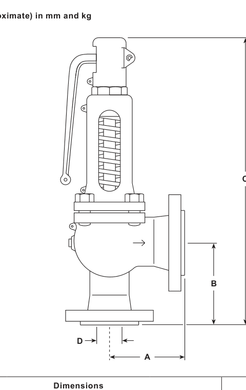
Approximate SV604 dimensions and weights | |||||
Inlet/outlet | A (mm) | B (mm) | C (mm) | Flow Ø (mm) | SV604 weight (kg) |
|---|---|---|---|---|---|
DN20–DN32 | 85 | 95 | 385 | 17.0 | 10.5 |
DN25–DN40 | 100 | 105 | 435 | 23.8 | 12.5 |
DN32–DN50 | 110 | 115 | 450 | 30.6 | 16.0 |
DN40–DN65 | 115 | 140 | 520 | 38.0 | 18.0 |
DN50–DN80 | 120 | 150 | 535 | 50.1 | 20.0 |
DN65–DN100 | 140 | 170 | 710 | 59.0 | 40.0 |
DN80–DN125 | 160 | 195 | 790 | 73.0 | 56.0 |
DN100–DN150 | 180 | 220 | 835 | 91.0 | 77.0 |
DN125–DN200 | 200 | 250 | 1042 | 105.0 | 120.0 |
DN150–DN250 | 225 | 285 | 1165 | 125.0 | 190.0 |
Dimension C may vary by up to 10 mm depending on the bonnet or cap configuration. Dimensions and weights are approximate and should be checked before final layout and lifting planning.
SV604 selection and ordering guide
Selection codes relevant to SV604 | |
Selection field | SV604 option |
|---|---|
Model type | SV60 |
Body material | 4 = carbon steel |
Configuration | A = closed bonnet/easing lever; B = closed bonnet/sealed cap; C = closed bonnet/packed lever, DN20–DN100 only; D = open bonnet/easing lever |
Seal/spring material | S = stainless steel with chrome-vanadium alloy spring; T = stainless steel with tungsten-alloy spring, only with open bonnet |
Size | DN20 to DN150 |
Inlet connection | PN40 or ASME (ANSI) 300, with the corresponding documented outlet route |
Documented ordering example: one SV604AS, DN20 flanged PN40 safety valve with a set pressure of 6 bar g. This example illustrates the code structure; the actual set pressure and configuration must be selected from the duty.
Scope and safe use
This installation and maintenance fragment preserves the SV604-relevant instructions from IM-P317-01, CTLS Issue 13. Safe operation can only be guaranteed when the valve is correctly installed, commissioned and maintained by a qualified person in accordance with the instructions, plant-construction safety rules and suitable tools and protective equipment.
Before installation, compare the valve name-plate and the current technical information with the intended application. Confirm the material, pressure, temperature, fluid, set pressure, installation direction and discharge arrangement. If the valve limits are lower than the system limits, or a malfunction could create dangerous overpressure or overtemperature, the system must include a suitable protective device.
1. General safety information
1.1 Intended use
SV604 is documented for steam, air, inert industrial gases and liquids within the stated Group 2 service boundary. Contact Spirax Sarco before using another fluid.
Check fluid/material compatibility and the maximum and minimum pressure and temperature values.
Determine the correct installation situation and direction of flow. Do not expose the valve to unconsidered external stresses from connected pipework or equipment.
Remove protective covers from connections and protective film from name-plates before installation on steam or other high-temperature service.
1.2–1.4 Access, lighting and pipeline contents
Provide safe access and, where needed, a guarded working platform and suitable lifting equipment. Provide adequate lighting for detailed work. Establish what is or has been in the pipeline, including flammable or harmful substances, temperature extremes and other hazards.
1.5–1.8 Environment, system, pressure and temperature
Assess explosion risk, lack of oxygen, dangerous gases, hot surfaces, fire risk, excessive noise and moving machinery. Consider the effect of the planned work on the complete system: closing valves or isolating controls must not disable another protective device. Isolate pressure and vent it safely to atmosphere; do not assume the system is depressurised because a gauge reads zero. Allow temperature to normalise after isolation to avoid burns.
1.9–1.12 Tools, protective clothing, permits and handling
Have suitable tools and consumables ready and use genuine replacement parts.
Assess the need for protection against chemicals, hot or cold surfaces, noise, falling objects and eye or face hazards.
All work must be carried out or supervised by a competent person. Follow the site permit-to-work system and post warning notices where required.
Where the valve weighs more than 20 kg, use suitable lifting equipment. Never carry a safety valve by its easing lever.
1.13–1.17 Residual hazards, freezing, disposal and returns
The external surface can become very hot, potentially above 200 °C at maximum permitted conditions. The valve may not be self-draining, so take care when removing it. Protect an idle valve from frost damage where freezing is possible.
Do not dismantle the valve until the compression on the control spring has been released. The guide states that the valve may contain a Viton component. If such material has been exposed to a temperature approaching 315 °C, it may decompose and form hydrofluoric acid; avoid skin contact and inhalation of dust or fumes. Where a Viton seat is fitted, follow the guide's disposal precautions and applicable local rules. When returning a contaminated or damaged valve, provide written information about the hazards and precautions.
2. General product information
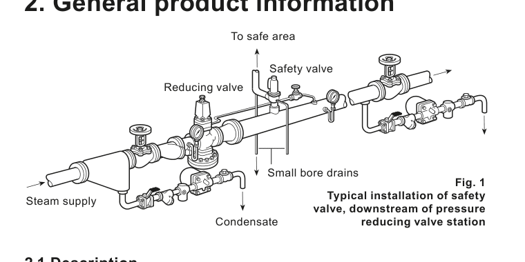
SV604 is a carbon-steel full-lift flanged safety valve for steam, inert industrial gas and water services. It is suitable for protecting steam boilers, pipelines, pressure vessels, compressors, receivers and general process equipment. The inlet size range is DN20 to DN150. The valve can be supplied with the documented easing-lever and bonnet/cap configurations; configuration, spring and connection must be selected from the technical information for the duty.
The documentation records the applicable pressure-equipment marking and category information, SV604 TÜV approvals to AD-Merkblatt A2, AD-Merkblatt A4, TRD 421, Vd TÜV 100 and 100/4, Lloyd’s Register type approval certificate 01/00125 (E2), and seat tightness to ASME/API Standard 527-1992. A manufacturer’s Typical Test Report is supplied as standard and includes the set and hydraulic test pressure. Material certification to EN 10204 3.1 is available on request.
3. Supply
The valve is normally supplied set at the required pressure, sealed and ready for the specified service. Setting must only be performed by authorised, competent persons. Spirax Sarco accepts no responsibility for a valve reset by unauthorised personnel.
4. Handling and storage
Transport the valve in the upright position.
Do not drop the valve and avoid sudden shocks or heavy impacts.
Keep the valve in the supplier’s packaging until it is required.
Never lift or carry the valve by the easing lever.
5. Before fitting the valve
Confirm that the planned installation matches the typical arrangement and the system design.
Check that all name-plate details comply with the installation and process.
Blow through the pipework before fitting the valve so foreign matter cannot reach the seat and cause leakage.
Check the name-plate to confirm the correct set pressure.
Remove protective caps and seals.
Remove plastic securing straps from the easing lever when appropriate.
6. Installation
Read the safety information before any installation work. The spring housing centre line must be vertically above the valve, and the main axis must be vertical upwards.
Fit the valve to the pipework or vessel using the shortest possible pipe or fitting.
Do not install an intervening valve or fitting that could isolate the safety valve.
Do not make the inlet pipe connection smaller than the valve inlet.
Make the outlet pipe at least as large as the valve outlet. Use long-radius bends and fittings to keep backpressure below 10% of set pressure.
Route the outlet to a safe discharge point where operation cannot injure people or damage property.
Support the outlet pipework so it does not impose undue stress on the valve.
When an outlet rises on steam service, provide a small-bore drain at the lowest point and route it to a safe location.
Where condensate can accumulate in the body, route the ½ inch BSP body drain connection to a safe drainage point.
Give each safety valve its own unrestricted discharge pipe.
Open-bonnet valves may release fluid under pressure when discharging; make sure this can happen safely.
Limit safety-valve lagging to the body only.
Expect sudden operation and high surface temperature on steam systems. Use suitable protection.
7. Damage prevention
Excessive inlet pressure loss during relief can make the valve open and close rapidly, causing chattering or hammering. This can reduce capacity, damage seating faces and other parts, and cause leakage after normal pressure returns.
Inlet pressure loss should be no more than 3% of the pressure differential between set pressure and superimposed backpressure during discharge. Position the valve 8–10 pipe diameters downstream of converging or diverging fittings or bends. Use inlet branches with a smooth approach and adequate area.
8. Commissioning
After installation, check for leaks at both inlet and outlet connections.
Raise system pressure in a controlled manner and verify operation at the correct set pressure. For SV604/SV60 service, confirm that overpressure is limited to 5% of set pressure for the rated steam condition.
Reduce system pressure to the normal operating pressure and check that the valve reseats.
9. Testing during use
Test correct operation regularly, at least every 12 months, as part of a documented and controlled procedure. The interval must be determined from the application, system conditions and the requirements of the user or responsible insurance company. Use protection against excess heat and noise during testing.
Where an easing lever is fitted, operate it only when system pressure is at least 85% of the set pressure. Operate it by hand only. Do not use a tool, pipe extension or other mechanical device, and do not apply excessive force.
10. Guidelines for setting
10.1 Choice of set pressure
Set pressure must be selected against the safe working pressure or design pressure of the protected plant, in accordance with the applicable pressure-system code such as BS 5500 where relevant. The valve must achieve its rated capacity with no more than 5% overpressure for the documented SV60 steam condition. If set pressure is too close to normal operating pressure, the valve may operate prematurely or fail to close satisfactorily when pressure returns to normal.
Allow adequate differential between the maximum system operating pressure and the set pressure so that the valve can reseat. The operating pressure varies, and the set pressure must accommodate normal fluctuations. The guide defines the re-seat differential as 10% of set pressure, with a minimum of 0.3 bar, and identifies normal system pressure variation separately when establishing the setting window.
10.2 Setting the valve
Only an authorised and competent person may alter the set pressure. Spirax Sarco cannot accept responsibility for unauthorised alteration.
10.3 Valves supplied unset
Where an unset valve is supplied to an approved agent, the set-pressure tag must be stamped with the pressure in bar after setting, permanently attached with locking wire and lead seal. The instruction label indicates the pressure range of the fitted spring.
11. Maintenance
All safety valves require planned maintenance. Before maintenance, read the safety information, isolate and safely vent the system, allow the valve to cool, and make sure the control spring is released before dismantling.
The guide recommends returning SV604 safety valves to Spirax Sarco or an approved agent for periodic overhaul. Inspection and overhaul frequency depends on operating conditions, frequency of operation and media. An internal inspection is recommended after no more than five years in service, or as agreed with the insurance company. The valve should be overhauled, tested, reset and sealed using controlled procedures.
Disc and skirt assemblies are non-serviceable and must not be repaired or rectified. If an assembly is damaged, replace it with a new assembly or use an approved Spirax Sarco repair specialist. Use only genuine replacement parts and retain the test, reset and seal records with the project documentation.
Sales brochures
| Document | Reference | Language | Download |
|---|---|---|---|
| Safety valves overview | SB-S13-60-EN | English | Download |
Technical information
| Document | Reference | Language | Download |
|---|---|---|---|
| SV60 Safety Valve — Technical Information | TI-S13-27 | English | Download |
Installation and maintenance
| Document | Reference | Language | Download |
|---|---|---|---|
| SV60 and SV60H Safety Valves — Installation and Maintenance Instructions | IM-P317-01 | English | Download |