

DP17 pilot operated pressure reducing valve
Spirax Sarco DP17 is a pilot operated pressure reducing valve for controlling downstream steam pressure in process and utility systems. It is intended for applications where a stable reduced pressure is needed at the point of use, while the upstream supply pressure and process demand vary within the documented operating envelope. The valve uses a pilot control arrangement, an adjustable pressure spring and a main valve assembly so that the downstream pressure signal can regulate the main flow path.
The DP17 is primarily documented for steam service. The current supplementary safety information identifies steam, air and inert industrial gases in Group 2 as intended media, but it also requires the installer to check material suitability, pressure and temperature before use. Use on any other fluid needs confirmation from the manufacturer. This distinction matters when a project moves from a steam duty to compressed air or another gas: the service, temperature, seal compatibility and protection requirements must be confirmed for the exact valve being ordered.
How the DP17 controls pressure
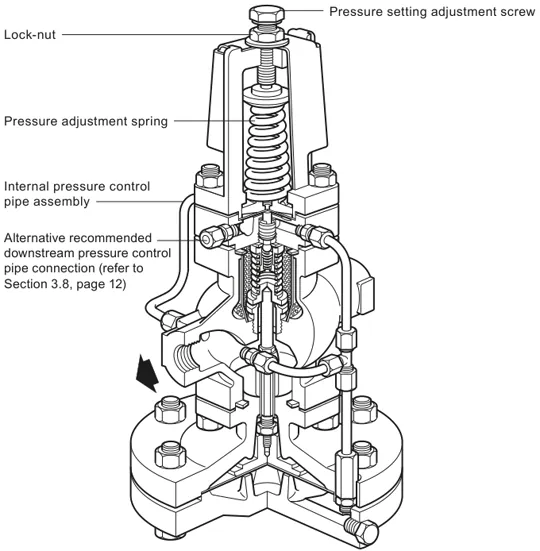
The pilot valve senses the reduced pressure and controls pressure in the main diaphragm chamber. The main valve then modulates to admit only the flow needed to maintain the downstream set point. The pressure adjustment spring provides the local set-point input, and the internal pressure control pipe returns the downstream signal to the pilot circuit. This arrangement gives the DP17 a practical route to pressure control without an external electrical control signal.
A variable-rate conical pressure adjustment spring is fitted for a downstream pressure range of 0.2-17 bar g. The adjustment range is not a promise that every installation can operate at every point in that band: the available pressure reduction, steam condition, valve capacity, pipework and downstream equipment all remain part of the selection check. The maximum differential pressure is limited to the maximum operating pressure, and the pressure-temperature graph must be respected for the selected connection standard.
For applications requiring closer control, improved stability or maximum capacity conditions, the installation instructions describe replacing the internal pressure control pipe with an external connection. The external line is connected to the top of the reduced-pressure main in a calm, straight section and is arranged with a positive fall so condensate can drain away from the valve. This is an installation option for a defined duty, not a reason to bypass the normal pressure-control arrangement.
Where DP17 fits in a steam system
A DP17 pressure reducing station normally sits after upstream isolation and steam-conditioning equipment and before the protected low-pressure distribution or process equipment. The documented recommended arrangement includes an upstream separator with a trap set, a 100 mesh strainer, upstream and downstream pressure gauges, and a downstream safety valve. These items have distinct jobs: the separator and trap set help deliver dry steam, the strainer limits dirt reaching the pilot and main valve, the gauges make setting and monitoring possible, and the safety valve protects equipment if the pressure reducing valve fails in an open condition.
The DP17 can be considered for a single pressure reducing duty, and the instructions also describe parallel and series arrangements for wider operating requirements. Parallel valves can be used where capacity or load variation requires a staged arrangement. For pressure turndown above 10 to 1, a series arrangement may need consideration, with correctly sized intermediate pipework equivalent to at least 50 pipe diameters and adequate drainage between the valves. These arrangements should be designed as a station rather than treated as a change to the single-valve specification.
Pipework on both sides of the valve should be sized so that velocity does not exceed 30 m/s. Line stresses caused by thermal expansion, inadequate supports or misalignment must not be transferred into the valve body. Full-bore isolation is preferred. If downstream control equipment is fast acting, it should be separated from the DP17 by at least 50 pipe diameters where practicable, or by an intermediate vessel, to limit pressure pulses and protect stable operation. Downstream pipework must also be properly trapped so condensate does not accumulate at the valve outlet.
Documented DP17 operating envelope
The Spirax Sarco DP17 body design condition is PN25. The maximum allowable pressure is 25 bar g at 120 deg C, the maximum allowable temperature is 232 deg C and the minimum allowable temperature is -10 deg C. For saturated steam, the maximum operating pressure is 17 bar g. The maximum operating temperature is 232 deg C and the minimum operating temperature is 0 deg C; lower operating temperatures require consultation with the manufacturer. A cold hydraulic test may be carried out up to 38 bar g, but with the internals fitted the test pressure must not exceed 25 bar g.
These values are limits and selection checks, not a substitute for sizing. In particular, the 17 bar g steam operating limit does not mean that downstream pressure, upstream pressure, differential pressure and capacity can be chosen independently. Confirm the steam pressure and temperature at the valve, the required downstream set point, the load range, the connection standard and the safe working pressure of the downstream plant. The downstream safety valve set point must be below the safe working pressure of the protected equipment and must account for the no-load pressure setting and the safety valve reseat characteristic.
Connections and selection checks
DP17 is available in DN15LC, DN15, DN20, DN25, DN32, DN40 and DN50 sizes. Screwed connections are BSP parallel, with NPT available for DN15 to DN25 only. Documented standard flange options include BS 4504 PN16 and PN25 across DN15-DN50; BS 10 Table H and ANSI 300 for DN25-DN50; and JIS 10, JIS 16 and ANSI 150 across DN15-DN50. BS 10 Table F for DN15-DN20 and ANSI 300 for DN15 are listed as available on request. The exact connection, nominal size, pressure class and local standard must be confirmed before an enquiry is converted into an order.
When preparing an enquiry, state the required size, connection type, upstream pressure, downstream pressure, minimum and maximum load, steam condition, operating temperature, installation orientation and downstream protection arrangement. Where a gas service is intended, include the gas composition and confirm the permitted service boundary before selecting the valve.
For broader family-level planning, the pressure reducing valve range provides the surrounding product context. The DP17 page remains limited to the exact model: it does not add variants, spare parts, alternate spring ranges or connection options that have not been verified for DP17.
Installation, commissioning and maintenance expectations
Install the DP17 in a horizontal pipeline with the main diaphragm chamber below the line. Clear loose dirt from the upstream pipework before commissioning, inspect the strainer screen and open the upstream isolation valve slowly. For the standard local adjustment, start with the spring slack, open the pressure gauge isolating cocks, turn the adjustment screw clockwise until the required downstream pressure is reached, secure the lock-nut and then open the downstream valve slowly. After installation or maintenance, test the complete system and any alarms or protective devices.
Maintenance is part of the selection decision for a pressure reducing station. The instructions recommend a complete overhaul every 12-18 months, ideally with the valve removed from the line. The main valve seat and head, pilot valve chamber, strainer screen, main diaphragms and pilot diaphragms should be inspected and refurbished or replaced as necessary. Any intervention requires isolation and safe venting of pressure, time for hot surfaces to cool, competent personnel and suitable protective equipment. Use genuine replacement parts and follow the full installation and maintenance instruction supplied with the valve.
With the operating envelope, station protection and maintenance access confirmed, Spirax Sarco DP17 offers a clearly defined pilot operated route for reducing steam pressure. The final selection should always be checked against the current technical evidence, the actual plant conditions and the pressure rating of every downstream component.
1. Product description and service boundary
The DP17 is a pilot operated pressure reducing valve. The detailed instructions primarily describe use on steam and can be used as a guide when the valve is used on compressed air. The current supplementary safety information identifies steam, air and inert industrial gases in Group 2 as intended media. Use on other fluids requires confirmation of product suitability.
The limits and adjustment range below apply to DP17. Do not transfer the limits of other variants in the wider source document to this valve.
2. Sizes and pipe connections
| Connection or size item | DP17 information |
|---|---|
| Nominal sizes | DN15LC, DN15, DN20, DN25, DN32, DN40 and DN50. |
| Screwed connections | BSP parallel. NPT is available for DN15 to DN25 only. |
| Standard flanges | DN15-DN50 BS 4504 PN16 and PN25; DN25-DN50 BS 10 Table H and ANSI 300; DN15-DN50 JIS 10, JIS 16 and ANSI 150. |
| On request | DN15-DN20 BS 10 Table F and DN15 ANSI 300. |
Confirm the nominal size, connection type and pressure class against the local piping standard and the actual enquiry duty.
3. Pressure and temperature limits
| Parameter | DP17 limit or condition |
|---|---|
| Body design condition | PN25. |
| PMA | 25 bar g at 120 deg C. |
| TMA | 232 deg C. |
| Minimum allowable temperature | -10 deg C. |
| PMO for saturated steam | 17 bar g. |
| Maximum operating temperature | 232 deg C. |
| Minimum operating temperature | 0 deg C. Consult the manufacturer for lower operating temperatures. |
| Pressure adjustment range | 0.2-17 bar g, provided by the variable-rate conical pressure adjustment spring. |
| Maximum differential pressure | Limited to the PMO. |
| Maximum cold hydraulic test pressure | 38 bar g. With internals fitted, test pressure must not exceed 25 bar g. |
The pressure-temperature graph in the source instruction must be used with the connection-specific envelope. Do not operate the valve in a prohibited region or combine the maximum pressure and temperature values without checking the graph.
4. Technical selection notes
- Use the operating pressure, temperature and load range at the valve to confirm the size and pressure reduction duty.
- Keep the downstream pressure within the spring adjustment range and within the safe working pressure of the protected equipment.
- Use a downstream safety valve where a failure-open condition could create excessive pressure.
- Do not infer material suitability or capacity from the product family name alone.
Installation and Maintenance Guide
- Safety and intended use
- Fitting and station arrangement
- Commissioning
- Routine maintenance
- Service safety and fault checks
1. Safety and intended use
Safe operation depends on correct installation, commissioning, use and maintenance by qualified personnel who follow the operating instructions and applicable pipeline safety requirements.
Check the service
Confirm that the valve, materials, pressure, temperature and connection are suitable for the intended duty. The supplementary safety information identifies steam, air and inert industrial gases in Group 2 as intended media. Suitability for another fluid must be confirmed before installation.
Isolate pressure
Before maintenance, isolate the valve and safely vent pressure to atmosphere. Consider double isolation and bleed arrangements, and do not assume that the system is depressurised only because a gauge reads zero.
Manage heat and access
Allow temperature to normalise after isolation. External surfaces may be very hot. Provide safe access, suitable lighting, lifting arrangements and protective clothing.
Protect the system
Check the direction of flow, avoid imposing pipeline stresses on the valve body, protect downstream equipment from excessive pressure and use only suitable tools and genuine replacement parts.
The DP17 is not self-draining. Take care when removing it from a line, and provide protection against freezing where the valve can be exposed to temperatures below the freezing point.
2. Fitting and station arrangement
The valve should always be installed in a horizontal pipeline with the main diaphragm chamber below the line. Pipework on both sides must be sized so that velocity does not exceed 30 m/s. Line stresses from expansion or inadequate support must not be imposed on the body.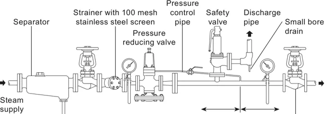
Dry and clean steam
Fit a separator with a trap set upstream to help ensure dry steam conditions. If the low-pressure line rises downstream of the valve, provide a further drain point so the valve remains drained after shutdown. Protect the valve with a pipeline strainer containing a 100 mesh stainless steel screen. Fit the strainer on its side to reduce water accumulation and inspect the screen regularly.
Pressure control pipe
For closer control, improved stability or maximum capacity conditions, the internal pressure control pipe may be replaced by an external pressure control pipe. Connect it to the top of the reduced-pressure main where there is at least 1 m or 15 pipe diameters of uninterrupted straight pipe in either direction, whichever is greater. Arrange the pipe with a positive fall so condensate drains away from the DP17.
Gauges and isolation
Install pressure gauges on both upstream and downstream sides. Use preferably full-bore isolation valves, and arrange the downstream isolating valve so that no-load conditions can be obtained when setting the reduced pressure.
Safety valve and control equipment
Fit a safety valve to protect the downstream equipment from excessive pressure. It should be set below the safe working pressure of the protected equipment and discharge to a safe location. Where fast-acting downstream control equipment is used, provide the separation or intermediate volume required to limit pressure pulses and prevent unstable operation. Downstream pipework must be properly trapped.
For large capacity, widely varying loads or standby requirements, two or more valves may be installed in parallel. For pressure turndown above 10 to 1, consider a series arrangement with correctly sized intermediate pipework equivalent to at least 50 pipe diameters and drainage between the valves. Where fast-acting downstream control equipment is installed, keep it at least 50 pipe diameters away from the DP17 where practicable, or use an intermediate vessel to limit pressure pulses.
3. Commissioning
- Confirm that all connections are correctly made and close the valves at the reducing valve station, including any bypass valves.
- Turn the adjustment screw fully anticlockwise until the pressure adjustment spring is slack.
- Open the pressure gauge isolating cocks. Clear loose dirt and hard particles from the upstream pipework and inspect the main strainer screen.
- Open the upstream isolating valve slowly until it is fully open.
- Using a 19 mm A/F spanner, turn the adjustment screw clockwise slowly until the downstream pressure gauge shows the required set pressure.
- Hold the adjustment screw in position, tighten the lock-nut to secure the setting and keep the washer in position.
- Open the downstream valve slowly until it is fully open.
After installation or maintenance, verify that the system is fully functional and test alarms and protective devices. For direct injection systems, blow through the approach pipework and the valve thoroughly after the initial blowdown to remove storage inhibitor before the product enters service.
4. Routine maintenance
The instructions recommend dismantling the valve for a complete overhaul every 12-18 months, ideally with the valve removed from the line. Inspect and refurbish or replace the main valve seat and head, pilot valve chamber assembly, main valve screen, main diaphragms and pilot diaphragms as necessary.
Strainer and pilot circuit
Isolate the DP17 and reduce pressure to zero before releasing the unions. Remove the relevant valve chamber assembly, clean the main valve screen and gasket faces, check that the main valve return spring is in position, fit a new gasket where required and reassemble the chamber. Bring the valve back into service using the commissioning sequence.
Diaphragms and main valve
Clean contact faces carefully and replace worn or damaged diaphragms. When servicing the main valve, inspect the head and seat for wear, clean scale and dirt, and reset the assembly according to the size-specific procedure in the complete instruction. Retighten unions to obtain a steam-tight seal before recommissioning.
Maintenance work must be supervised by a competent person. Follow the complete installation and maintenance instruction for dismantling sequence, tightening torques, component orientation, spare-part identification and fault finding.
5. Service safety and fault checks
Before investigating low or high downstream pressure, confirm that the valve is correctly isolated when the task requires dismantling. A low downstream pressure can be associated with insufficient upstream pressure, a blocked strainer or control pipe, a blocked control orifice, damaged diaphragms or an undersized valve. A high downstream pressure can be associated with a blocked downstream pressure control pipe, damaged pilot diaphragms, a sticking pilot or main valve that is not seating.
If the valve hunts, first check whether upstream pressure is stable and whether the valve is correctly sized for the full-load condition. Then check steam dryness, pressure-control pipe location, dirt in the pipe assembly and the freedom of the pilot and main valve mechanisms. Do not change the pressure setting or bypass the safety valve as a substitute for correcting the installation or sizing fault.