
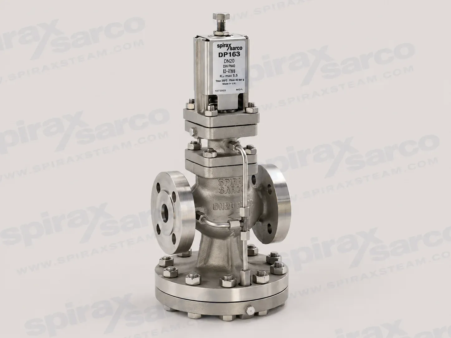
DP163-PRESSURE-REDUCING-VALVE
DP163 Pilot Operated Pressure Reducing Valve
DP163 is a stainless steel pilot operated pressure reducing valve for steam, available from DN15LC to DN80 with documented spring ranges and pressure-temperature limits.
Spirax Sarco DP163 pressure control overview
Spirax Sarco DP163 is a pilot operated pressure reducing valve with a stainless steel body for steam applications. It is intended for pressure reduction duties where a controlled downstream pressure must be maintained as steam demand and upstream conditions change within the documented operating limits. The valve uses a pressure adjustment spring, pilot valve, diaphragms, control pipework and a main valve to translate downstream pressure into a controlled opening of the main flow path. This arrangement gives the designer a practical, self-acting pressure control point without adding an electrical actuator to the valve assembly.
The DP163 should be selected as one part of a complete steam pressure reducing station. The valve itself is only one element in the pressure boundary: upstream isolation, filtration and condensate drainage affect the quality of steam reaching the pilot and main valve, while downstream pressure indication and overpressure protection determine whether the reduced-pressure equipment is properly protected. The product documents therefore link valve size, connection standard, pressure setting, steam condition and installation layout rather than treating the nominal pipe size as a complete selection decision.
How the DP163 controls downstream pressure
During operation, the pilot control circuit responds to the pressure sensed downstream of the reducing valve. The pressure adjustment spring establishes the requested downstream range, and the pilot and diaphragm assembly modulate the main valve in response to the control pressure. The result is a pressure-reducing device that can be applied to medium-duty or process-type steam services, branch lines and equipment supply points when the required flow and pressure conditions are within the product data.
Two DP163 pressure adjustment spring ranges are documented. The red spring covers downstream pressures from 0.2 to 17 bar g, while the grey spring covers 16.0 to 21 bar g. Because the ranges overlap between 16 and 17 bar g, the spring colour should be selected against the required set pressure and the ordering details confirmed before the valve is supplied. The spring fitted for the pressure quoted on the order is suitable for that duty, but the valve is supplied without being pre-set; commissioning must establish the actual downstream setting on site.
Stainless steel construction for steam service
The DP163 uses stainless steel throughout the pressure-control assembly. The technical information identifies stainless steel for the body, main valve and seat, pilot valve housing, pilot components, diaphragms, control pipe assembly and balance pipe assembly, with individual material grades listed in the technical section below. This gives the page a clear material boundary: the DP163 described here is the stainless steel steam model, and the material suitability, pressure rating and temperature rating still need to be checked against the actual plant conditions.
The valve is available in DN15LC, DN15, DN20, DN25, DN32, DN40, DN50 and DN80. DN15LC is the low-capacity version. Standard flanged connections are EN 1092 PN25 and PN40, BS 10 Table J and ASME/ANSI 300; ASME/ANSI 150 and JIS 20 can be supplied on request. The selected flange standard is important because the pressure-temperature limits differ between the standard flange group and ASME/ANSI 150. Connection standard, nominal size and the required downstream pressure should therefore be settled together rather than specified independently.
Capacity, sensing and steam condition
Maximum Kv values range from 1.0 for DN15LC to 64.0 for DN80. The values are full capacities and are intended to support safety valve sizing as well as valve selection. They do not replace a sizing calculation: the required flow, upstream pressure, downstream pressure, steam state and allowable pressure drop must be compared with the capacity chart. A valve that is nominally the same size as the supply pipe may not be the correct choice, and a properly selected reducing valve is often smaller than the upstream pipework while the downstream pipework is larger.
The published steam capacity chart is based on an external downstream pressure sensing pipe. The internal balance pipe is useful in suitable installations, but at low downstream pressure it can reduce the available valve capacity by up to approximately 30%. When closer control, improved stability or maximum capacity is needed, the installation instructions describe replacing the internal balance arrangement with an external pressure sensing pipe. The sensing connection should enter a calm section of the reduced-pressure main with at least 1 m or 15 pipe diameters of uninterrupted straight pipe on either side, whichever is greater.
Steam condition also changes the available capacity. The chart is used for saturated steam; for superheated steam, the technical information specifies a correction factor of 0.95 at 55 °C of superheat and 0.90 at 100 °C of superheat. The correction is applied to the chart result before checking the required load. This is why a load calculation should record whether the steam is saturated or superheated instead of relying on a single nominal flow figure.
Pressure and temperature limits
DP163 pressure limits are conditional on connection standard and temperature. With the standard flanged group identified in the technical information, the maximum design pressure is 36.4 bar g at 20 °C, the maximum upstream saturated steam pressure and maximum differential pressure are 25 bar g, and the maximum operating temperature is 250 °C at 24 bar g. For ASME/ANSI 150, the corresponding maximum design pressure is 18.9 bar g at 20 °C, the maximum upstream saturated steam pressure and maximum differential pressure are 14 bar g, and 250 °C is permitted at 12.1 bar g. The minimum operating temperature is 0 °C; lower operating temperatures require consultation with Spirax Sarco.
These values are not a permission to operate at every pressure-temperature combination in the table. The pressure-temperature curve, flange group, spring choice, steam condition and system safety requirements must all be considered. The valve is designed for a maximum cold hydraulic test pressure of 60 bar g, but with internals fitted the test pressure must not exceed 40 bar g. A downstream safety valve remains necessary where a failed-open reducing valve could expose downstream equipment to excessive pressure.
Installation conditions that protect control performance
The DP163 is installed in horizontal pipework with the main diaphragm chamber below the line. Steam should be adequately drained and as dry as practical; the installation guide recommends a separator in the steam supply. An upstream strainer of the same size as the upstream pipework should use a 100 mesh screen and be fitted on its side so that water does not accumulate in it. Line stresses caused by thermal expansion or inadequate support must not be imposed on the valve body, and pipeline velocities on both sides should remain at or below 30 m/s.
A downstream pressure gauge is essential for setting the valve, and an upstream gauge is a useful diagnostic aid. The station should include a safety valve sized and set to protect the reduced-pressure system, with discharge pipework taken to a safe place. If downstream equipment is fast acting, the installation instructions call for a separation of at least 50 pipe diameters or an intermediate vessel to limit pressure pulses reaching the DP163. Where a bypass is essential for continuity of supply, it should normally be the same size as the reducing valve, located above or to the side of the main assembly, padlocked against unauthorised use and manually supervised.
Maintenance and ordering checks
A complete overhaul is recommended every 12 to 18 months, ideally with the valve removed from the line. The maintenance instructions identify the main valve and seat, pilot valve assembly, pilot diaphragms and main diaphragms as parts that may need replacement or refurbishment, with control orifices, control pipework, fittings and balance pipe kept clear of scale and dirt. Because 316 stainless steel screwed and close-fitting parts are susceptible to galling or cold welding, dismantling and reassembly require particular care; where the application permits, the instructions recommend a light smear of PTFE-based grease on mating parts.
Before ordering, confirm the model, size, flange standard, spring range, pressure setting, steam pressure and temperature, sensing arrangement, certification requirement and downstream protection. EN 10204 3.1 certification is available when specified at the time of order. The product attachments provide the full technical and installation documents for checking dimensions, capacity curves, pressure-temperature boundaries, commissioning and service procedures.
Choosing the right pressure reducing route
For a different pilot-operated steam pressure reducing comparison, review the published DP27 pressure reducing valve page. If the design brief calls for another pressure reducing product in the same control-systems category, the 25P pressure reducing valve page provides a separate selection route. Where the duty is compact and direct-acting rather than pilot operated, compare the BRV2S direct acting pressure reducing valve. These links support product selection; they do not expand the DP163 page into a multi-model specification.
In summary, Spirax Sarco DP163 is best specified from the steam load and pressure duty outward: establish the required downstream pressure and steam flow, apply the correct sensing and superheat assumptions, select the size and connection standard from the documented limits, then design the surrounding station for dry steam, filtration, drainage, measurement and overpressure protection. This approach uses the strengths of the stainless steel pilot operated design while keeping the pressure, temperature, capacity and maintenance boundaries visible to the engineer.
Description
The DP163 is a pilot operated pressure reducing valve manufactured using stainless steel and intended for steam applications. The valve is supplied with a pressure adjustment spring selected for the downstream pressure quoted at order, but the spring is not pre-set.
The valve complies with the requirements of the EU Pressure Equipment Directive and UK Pressure Equipment (Safety) Regulations and carries the required mark where applicable. Certification to EN 10204 3.1 is available; certification and inspection requirements must be stated when the order is placed.
Sizes and pipe connections
DP163 is available in DN15LC (low capacity), DN15, DN20, DN25, DN32, DN40, DN50 and DN80.
| Connection group | Connection standards |
|---|---|
| Standard flanges | EN 1092 PN25 and PN40; BS 10 Table J; ASME/ANSI 300 |
| Available on request | ASME/ANSI 150; JIS 20 |
Kv values
The maximum Kv values below are full capacities and should be used for safety valve sizing purposes as well as valve selection.
| Size | DN15LC | DN15 | DN20 | DN25 | DN32 | DN40 | DN50 | DN80 |
|---|---|---|---|---|---|---|---|---|
| Nominal inch | 1/2 | 1/2 | 3/4 | 1 | 1 1/4 | 1 1/2 | 2 | 3 |
| Kv | 1.0 | 2.8 | 5.5 | 8.1 | 12.0 | 17.0 | 28.0 | 64.0 |
For conversion: Cv (UK) = Kv × 0.963; Cv (US) = Kv × 1.156.
Pressure and temperature limits
The operating envelope depends on the connection group and temperature. Do not use a single pressure or temperature value without checking the relevant curve and connection standard.
| Condition | Standard flange group | ASME/ANSI 150 group |
|---|---|---|
| Body design condition | PN40 | PN40 body; connection-specific limit applies |
| Maximum design pressure | 36.4 bar g at 20 °C (528 psi g at 68 °F) | 18.9 bar g at 20 °C (274 psi g at 68 °F) |
| Maximum design temperature | 250 °C at 24 bar g (482 °F at 348 psi g) | |
| Minimum design temperature | -10 °C (14 °F) | |
| Maximum upstream pressure for saturated steam | 25 bar g (363 psi g) | 14 bar g (203 psi g) |
| Maximum operating temperature | 250 °C at 24 bar g (482 °F at 348 psi g) | 250 °C at 12.1 bar g (482 °F at 175 psi g) |
| Minimum operating temperature | 0 °C (32 °F); consult Spirax Sarco for lower operating temperatures | |
| Maximum differential pressure | 25 bar (363 psi) | 14 bar (203 psi) |
| Maximum cold hydraulic test pressure | 60 bar g (870 psi g); with internals fitted, do not exceed 40 bar g (580 psi g) | |
Pressure adjustment springs
| Colour | Downstream pressure range |
|---|---|
| Red | 0.2 to 17 bar g (2.9 to 247 psi g) |
| Grey | 16.0 to 21 bar g (232 to 305 psi g) |
Materials
The following materials apply to the DP163 construction. Stainless steel grades and fastener details should be checked against the ordered valve and any required certification.
| Item | Part | Material | Material specification or detail |
|---|---|---|---|
| 1 | Adjustment screw | Stainless steel | BS 6105 A4/80 |
| 2 | Adjustment lock-nut | Stainless steel | BS 6105 A4/80 |
| 3 | Washer | Stainless steel | BS 1449 304 S16 |
| 4 | Spring housing | Stainless steel | DIN 3100 316 C12 |
| 5 | Top spring plate | Stainless steel | BS 970 431 S29 |
| 6 | Pressure adjustment spring | Stainless steel | BS 2056 302 S25 |
| 7 | Bottom spring plate | Stainless steel | BS 970 431 S29 |
| 8 | Spring housing securing nuts and studs | Stainless steel | Nuts BS 6105 A4/80; DN15 to DN50 studs M10 × 30 mm |
| 9 | Pilot diaphragm | Stainless steel | BS 1449 316 S31 |
| 10 | Pilot valve housing | Stainless steel | BS 3100 316 C12 |
| 11 | Pilot valve plunger | Stainless steel | BS 970 431 S29 |
| 12 | Spring housing cover | Stainless steel | BS 1449 304 S12 |
| 13 | Pilot valve and seat unit | Stainless steel | BS 970 431 S29 |
| 14 | Internal strainer | Stainless steel | BS 1449 304 S16 |
| Item | Part | Material | Material specification or detail |
|---|---|---|---|
| 15 | Body gasket | Stainless steel reinforced exfoliated graphite | — |
| 16 | Main valve return spring | Stainless steel | BS 2056 302 S25 |
| 17 | Main valve | Stainless steel | BS 970 431 S29 |
| 18 | Main valve seat | Stainless steel | BS 970 431 S29 |
| 19 | Balance pipe assembly | Stainless steel | BS 3605 304 S14 |
| 20 | Main valve body | Stainless steel | BS 3100 316 C12 |
| 21 | Pilot valve housing securing nuts and studs | Stainless steel | Nuts BS 6105 A4/80; studs M10 × 25 mm for DN15–DN20, M12 × 30 mm for DN25–DN50, M12 × 40 mm for DN80 |
| 22 | Main diaphragm chamber | Cast stainless steel | BS 3100 316 C12 |
| 23 | Main diaphragm securing nuts and bolts | Stainless steel | Nuts BS 3692 Grade 8; bolts M12 × 50 mm for DN15–DN20, M12 × 60 mm for DN25–DN32, M12 × 65 mm for DN40–DN50 and M12 × 80 mm for DN80 |
| 24 | Main diaphragms | Stainless steel | BS 1449 316 S31 |
| 25 | Main diaphragm plate | Stainless steel | BS EN 10088-3 1.4307 |
| 26 | Pushrod | Stainless steel | BS 970 431 S29 |
| 27 | Control pipe assembly | Stainless steel | BS 3605 304 S14 |
| 28 | Plug, 1/8 inch BSP | Stainless steel | BS 970 431 S29 |
| 29 | Pressure pipe union | Stainless steel | BS 970 316 S31 |
| 30 | Lock-nut | Stainless steel | BS 6105 A4/80 |
| 45 | DN80 body nuts and studs | Stainless steel | Nuts BS 3692 Grade 8; studs BS 6105 A4/80, M12 × 40 mm |
| 46 | DN80 upper main diaphragm chamber | Stainless steel | BS 3100 316 C12 |
Dimensions and weights
Dimensions are approximate and are given in mm (inches); weights are approximate and are given in kg (lb).
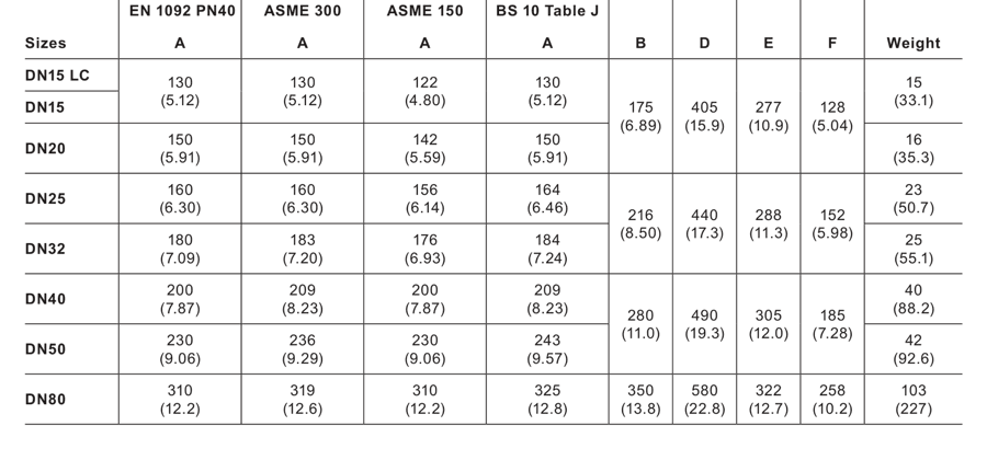
| Size | EN 1092 PN40 A | ASME 300 A | ASME 150 A | BS 10 Table J A | Weight |
|---|---|---|---|---|---|
| DN15LC | 130 (5.12) | 130 (5.12) | 122 (4.80) | 130 (5.12) | 15 (33.1) |
| DN15 | 130 (5.12) | 130 (5.12) | 122 (4.80) | 130 (5.12) | 15 (33.1) |
| DN20 | 150 (5.91) | 150 (5.91) | 142 (5.59) | 150 (5.91) | 16 (35.3) |
| DN25 | 160 (6.30) | 160 (6.30) | 156 (6.14) | 164 (6.46) | 23 (50.7) |
| DN32 | 180 (7.09) | 183 (7.20) | 176 (6.93) | 184 (7.24) | 25 (55.1) |
| DN40 | 200 (7.87) | 209 (8.23) | 200 (7.87) | 209 (8.23) | 40 (88.2) |
| DN50 | 230 (9.06) | 236 (9.29) | 230 (9.06) | 243 (9.57) | 42 (92.6) |
| DN80 | 310 (12.2) | 319 (12.6) | 310 (12.2) | 325 (12.8) | 103 (227) |
| Size group | B | D | E | F |
|---|---|---|---|---|
| DN15LC and DN15 | 175 (6.89) | 405 (15.9) | 277 (10.9) | 128 (5.04) |
| DN25 and DN32 | 216 (8.50) | 440 (17.3) | 288 (11.3) | 152 (5.98) |
| DN40 and DN50 | 280 (11.0) | 490 (19.3) | 305 (12.0) | 185 (7.28) |
| DN80 | 350 (13.8) | 580 (22.8) | 322 (12.7) | 258 (10.2) |
Steam capacity
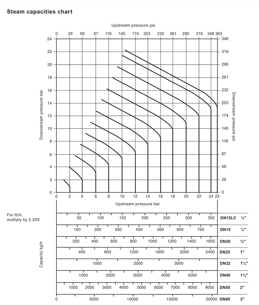
The capacities shown are based on a valve fitted with an external pressure sensing pipe. Relying on the internal balance pipe can reduce capacity, particularly at low downstream pressure, by up to approximately 30%.
Using the chart for saturated steam
For a valve required to pass 600 kg/h (1323 lb/h) while reducing from 6 bar (87.0 psi) to 4 bar (58.0 psi), find the intersection of the curved 6 bar upstream line and the horizontal 4 bar downstream line. Project down from that point to the capacity scales. Under the example conditions, DN32 (1 1/4 inch) is the smallest size that carries the required load.
Using the chart for superheated steam
Superheated steam has a higher specific volume, so apply a correction factor to the chart result. The factor is 0.95 for 55 °C (131 °F) of superheat and 0.90 for 100 °C (212 °F) of superheat. In the example above, a DN32 valve passing 740 kg/h of saturated-steam capacity at the chart point would pass 703 kg/h after the 0.95 correction for 55 °C superheat.
Spare parts and ordering
Available DP163 spare categories include the maintenance kit, main diaphragms, pilot diaphragms, pilot valve seal assembly, pilot valve and plunger assembly, main valve assembly, main valve return spring, pressure adjustment spring, control pipe assembly, balance pipe assembly, body gasket, securing stud and nut sets, diaphragm chamber securing bolts and nuts, and the pushrod and main diaphragm plate assembly.
The maintenance kit is a standby set covering the available parts marked for general maintenance. When ordering spare parts, state the description, valve size, model number and pressure rating. The complete installation and maintenance guide should be used for fitting procedures and tightening details.
Installation note and order example
Install the valve in horizontal pipework with the main diaphragm chamber below the line and with flow in the direction shown by the body arrow. For a complete station arrangement, follow the installation and maintenance information supplied with the valve.
Order example: one DN32 DP163 pilot operated pressure reducing valve with a red pressure adjustment spring and flanged EN 1092 PN25 connections.
Installation and Maintenance Guide
- Safety information
- General product information
- Installation
- Commissioning
- Maintenance
- Spare parts
- Fault finding
1. Safety information
Safe operation of the DP163 can only be guaranteed when it is installed, commissioned, used and maintained by qualified personnel in compliance with these operating instructions. General installation and safety instructions for pipeline and plant construction, together with the correct use of tools and safety equipment, must also be followed.
1.1 Intended use
Using this guide, the name-plate and the Technical Information Sheet, check that the DP163 is suitable for the intended steam application. The product complies with the applicable EU Pressure Equipment Directive and UK Pressure Equipment (Safety) Regulations requirements and carries the required mark where applicable.
| Valve size | Category |
|---|---|
| DN15 to DN32 | SEP |
| DN40 to DN80 | 1 |
- Check material suitability, pressure, temperature and their maximum and minimum values.
- If the product limits are lower than those of the system, or if a malfunction could create dangerous overpressure or overtemperature, provide a safety device to prevent the limit being exceeded.
- Determine the correct installation situation and direction of fluid flow.
- The product is not intended to withstand external stresses induced by the system. The installer must assess these stresses and take precautions to minimise them.
- Remove protection covers from connections and protective film from name-plates before installation on steam or other high-temperature applications.
1.2–1.6 Access, lighting, pipeline contents, environment and the system
- Provide safe access and, where necessary, a guarded working platform before working on the product. Arrange suitable lifting gear where required.
- Provide adequate lighting, particularly for detailed or intricate work.
- Consider what is or has been in the pipeline, including flammable materials, substances hazardous to health and extreme temperatures.
- Assess explosion-risk areas, lack of oxygen, dangerous gases, hot surfaces, fire hazards, excessive noise and moving machinery around the product.
- Consider the effect of the proposed work on the complete system. Isolation of vents or protective devices, or disabling controls or alarms, can put personnel and equipment at risk. Open and close isolation valves gradually to avoid system shocks.
1.7–1.11 Pressure, temperature, tools, clothing and permits
- Isolate pressure and safely vent the system to atmospheric pressure. Consider double isolation, locking or labelling closed valves. Never assume that the system is depressurised just because a pressure gauge reads zero.
- Allow time for temperature to normalise after isolation to avoid burns.
- Have suitable tools and consumables available and use genuine Spirax Sarco replacement parts.
- Assess the need for protective clothing against chemicals, high or low temperature, noise, falling objects and eye or face hazards.
- All work must be carried out or supervised by a competent person. Follow any formal permit-to-work system; where none exists, a responsible person should know the work being done and arrange assistance where necessary. Post warning notices if required.
1.12–1.16 Handling, residual hazards, freezing, disposal and returns
- Assess manual handling risks for large or heavy products and use an appropriate lifting or handling method.
- The external surface may become very hot in normal service, and products may retain fluid because they are not self-draining. Take care when dismantling or removing the valve.
- Protect the product against frost damage where it can be exposed to below-freezing temperatures.
- Unless stated otherwise, the product is recyclable and no ecological hazard is anticipated when it is disposed of with due care.
- When returning a product, provide written information about contamination residues, mechanical damage and any associated hazards, including relevant safety data sheets.
Warning: If the DP163 is not used in the manner specified by these instructions, the protection provided may be impaired.
2. General product information
The DP163 is a pilot operated pressure reducing valve with a stainless steel body for steam applications. It is supplied with a pressure adjustment spring selected for the downstream pressure stated on the order. The spring is not pre-set.
For additional product data, use the DP163 Technical Information Sheet. Available sizes are DN15LC, DN15, DN20, DN25, DN32, DN40, DN50 and DN80. Standard flanges are EN 1092 PN25 and PN40, BS 10 Table J and ASME/ANSI 300; ASME/ANSI 150 and JIS 20 are available on request.
2.1 Pressure and temperature limits
| Condition | Standard flange group | ASME/ANSI 150 group |
|---|---|---|
| Maximum design pressure at 20 °C | 36.4 bar g | 18.9 bar g |
| Maximum upstream saturated steam pressure | 25 bar g | 14 bar g |
| Maximum operating temperature | 250 °C at 24 bar g | 250 °C at 12.1 bar g |
| Minimum operating temperature | 0 °C; consult Spirax Sarco for lower operating temperatures | |
| Maximum differential pressure | 25 bar | 14 bar |
| Maximum cold hydraulic test pressure | 60 bar g; with internals fitted, do not exceed 40 bar g | |
The pressure-temperature curve and the ordered connection group must be checked together. Do not operate in a region marked as prohibited by the Technical Information Sheet.
3. Installation
3.1 Supply
The DP163 is supplied ready for fitting. The pressure adjustment spring is selected to suit the downstream pressure stated on the order, but it is not pre-set.
3.2 Fitting
Always fit the valve in horizontal pipework with the main diaphragm chamber below the line. For high capacities, widely varying loads or standby service, two or more valves may be installed in parallel.
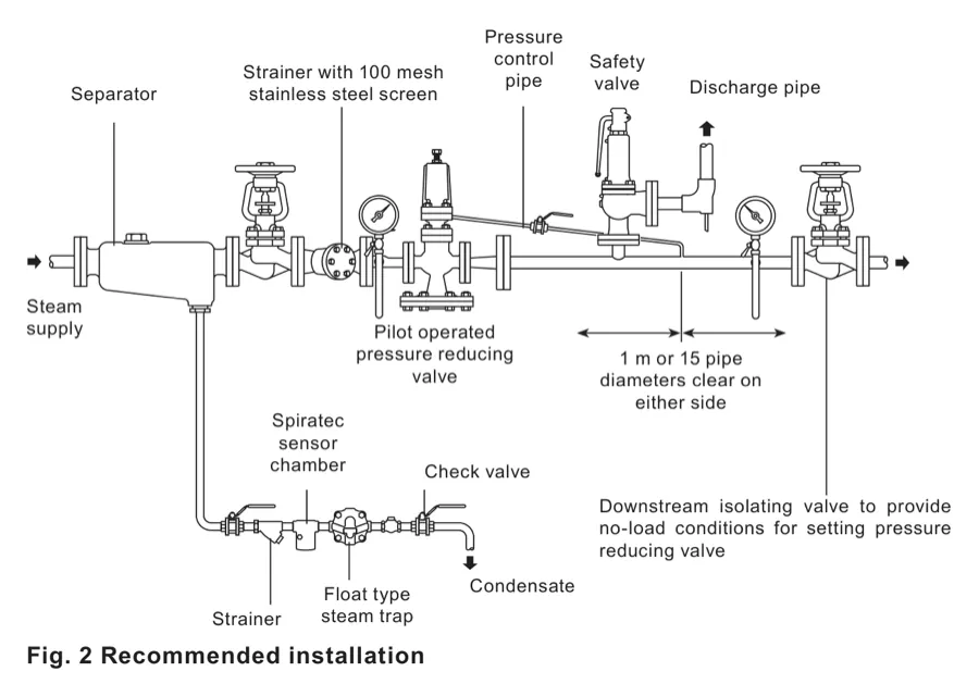
3.3–3.7 Pipeline sizing, stress, isolation, drainage and dirt
- Size the pipework on both sides so that velocity does not exceed 30 m/s. A correctly sized valve is often smaller than the upstream pipework, while the downstream pipework is generally larger.
- Do not impose line stresses caused by expansion or inadequate support on the valve body.
- Use fullway isolation valves where possible.
- Drain the pipework adequately so that the valve receives dry steam. A separator in the steam supply is the ideal arrangement. If closing the downstream isolation valves could flood the downstream pipework, install a trap set to remove condensate from radiant losses.
- Protect the valve with a strainer the same size as the upstream pipework and fitted with a 100 mesh screen. Fit the strainer on its side to prevent water accumulating.
3.8 Pressure sensing
For closer control, improved stability or maximum capacity conditions, replace the balance pipe with an external pressure sensing pipe as follows:
- Remove the balance pipe assembly.
- Blank the resulting 1/8 inch BSP tapping in the side of the body with the plug supplied in the linen bag attached to the valve.
- Blank the other 1/8 inch BSP tapping in the side of the pilot valve chamber with the plug fitted in the tapping on the front of the pilot valve chamber.
- Fit the supplied brass compression fitting and compression ring into the pilot valve chamber tapping. It accepts 6 mm outside-diameter pipe. If suitable pipe is unavailable, remove the fitting and screw 1/4 inch nominal-bore steel pipe directly into the pilot valve chamber.
- Connect the sensing pipe to the top of the reduced-pressure main at a point with at least 1 m or 15 pipe diameters of straight pipe, uninterrupted by fittings, in either direction, whichever is greater.
- Arrange the sensing pipe with a positive fall so condensate drains away from the DP163. Where a fall cannot be maintained when entering the top of a large reduced-pressure main, connect the pressure control pipe into the side of the main.
3.9 Pressure gauges
A downstream pressure gauge is essential so that the valve can be set correctly. An upstream pressure gauge is an essential diagnostic tool.
3.10 Bypass
If a constant steam supply must be maintained while the reducing valve is serviced, install a bypass. The bypass valve will normally be the same size as the reducing valve. Padlock the handwheel to prevent unauthorised use and keep the bypass under constant manual supervision. The bypass may be above or beside the main assembly, never below it.
3.11 Safety valve
Fit a safety valve to protect downstream equipment from excessive pressure. Set it to lift below the safe working pressure of the downstream equipment. It will normally be sized to pass the full capacity of the reducing valve if the DP163 fails fully open. Account for the safety valve reseat characteristic and the no-load pressure setting: for a DIN safety valve with a typical 10% blowdown, the minimum possible set pressure equals the no-load set pressure plus the blowdown value plus a margin of at least 0.1 bar. Take discharge pipework to a safe place.
3.12 Position in relation to other control valves
- Install system isolation valves upstream of the DP163.
- Keep downstream fast-acting control equipment, such as pulsed piston actuated valves, at least 50 pipe diameters away. If that is impractical, use an intermediate vessel to reduce transmitted pressure pulses.
- Where both a downstream safety valve and a control valve are used, fit the safety valve downstream of the control valve rather than between the DP163 and the control valve. This reduces nuisance operation from slight leakage while protecting the downstream system.
- Trap intermediate downstream pipework properly so condensate does not build up on the downstream side.
4. Commissioning
4.1 Start-up and setting the valve
- Ensure all connections are properly made and all valves are closed.
- Turn the adjustment screw fully anticlockwise until the spring is slack.
- Open the small valve in the pressure control line.
- Blow through the approach pipework by removing the cap and screen from the strainer protecting the steam trap that drains the upstream pipework. Replace them afterwards. Do not remove the screen from the main line strainer during this operation. Inspect and clean the main line strainer at regular intervals when necessary.
- Slowly open the upstream isolation valve until fully open.
- Using a 19 mm A/F spanner, slowly turn the adjustment screw clockwise until the desired downstream pressure is shown.
- Hold the adjustment screw with the spanner and tighten the lock-nut to secure the pressure setting, ensuring the C washer stays in position.
- Slowly open the downstream valve until fully open.
4.2 Two or more valves in parallel
For parallel valves, it is advantageous to use two unequal sizes: choose the smaller valve for lower loads and bring the larger valve into operation for normal and maximum demand. Set each valve independently against dead-end conditions with a downstream isolation valve closed. Set the smaller valve approximately 0.1 bar higher than the larger valve.
5. Maintenance
Before any maintenance, follow the safety information in Section 1.
Warning: The body gasket contains a thin stainless steel support ring that may cause physical injury if it is handled or disposed of incorrectly.
Warning for DP163: The 316 stainless steel used in the product, particularly in screwed or close-fitting parts, is susceptible to galling or cold welding. Take great care during dismantling and reassembly. Where the application permits, apply a light smear of PTFE-based grease to mating parts before reassembly.
5.1 Routine maintenance
Dismantle the valve for a complete overhaul every 12 to 18 months, ideally with the valve removed from the line. Parts that may require replacement or refurbishment include the main valve and seat, pilot valve assembly, pilot diaphragms and main diaphragms. Clean the pushrod liner bush, control pipework, fittings and control orifices of scale deposits when necessary.
5.2 Diaphragms and cleaning
If diaphragms are not renewed, do not turn them over; refit each diaphragm in exactly the same position as when removed. Keep the control orifices in the control pipe adaptors and the balance pipe clear of dirt. Blow through with compressed air if necessary. Do not use a drill on control orifices, because enlarging them can upset operation.
| Valve size | Diaphragm diameter |
|---|---|
| DN15LC, DN15 and DN20 | 125 mm |
| DN25 and DN32 | 166 mm |
| DN40 and DN50 | 230 mm |
| DN80 | 300 mm |
5.3 Pressure adjustment springs and ranges
| Colour | DP163 reduced-pressure range |
|---|---|
| Red | 0.2 to 17 bar |
| Grey | 16.0 to 21 bar |
5.4 Renew or change the control spring
- Release the lock-nut and turn the adjustment screw anticlockwise until the spring is slack.
- Slide out the C washer from beneath the lock-nut and remove the cover.
- Remove the old spring and replace it with the new spring, remembering the top spring plate.
- Replace the cover and C washer. Turn the adjustment screw clockwise until the desired pressure is obtained.
- Hold the adjustment screw and tighten the lock-nut, ensuring the C washer stays in position.
5.5 Renew the pilot valve assembly and bellows seal
- Isolate the reducing valve and reduce pressure to zero.
- Release the lock-nut and turn the adjustment screw anticlockwise until the spring is slack.
- Slide out the C washer and remove the cover.
- Remove the spring and top spring plate.
- Undo the four M10 nuts and remove the spring housing, bottom spring plate and diaphragms.
- Undo the pipework union nuts and release the 6 mm stainless steel pipework.
- Undo the pilot valve housing nuts and remove the housing, ensuring that the main valve spring remains correctly positioned on the main valve head.
- Unscrew the pilot valve assembly, including its integral strainer screen, with a 27 mm A/F socket and remove the plunger.
- Unscrew the bellows seal assembly with a 24 mm A/F socket and replace it if necessary.
- With the bellows seal removed, screw in the new pilot valve assembly and tighten to 115 N m.
- Insert the plunger from the top and check for a 0.7 mm gap between the plunger top and a straight edge across the diaphragm recess. Machine the plunger if necessary to achieve the gap, then remove sharp edges.
- Locate the bellows seal carefully over the plunger and tighten to 115 N m.
- Press the top of the bellows lightly onto the plunger and check with the straight edge for a slight clearance.
- Ensure gasket faces on the pilot valve block and body are clean, and the main valve spring is positioned correctly.
- Fit a new gasket and secure the pilot valve block with the nuts, using the torque table below.
- Refit the 6 mm stainless steel pipework and tighten union nuts for a steam-tight seal.
- Refit both diaphragms in the same orientation as removed, with all contact surfaces clean.
- Position the bottom spring plate and secure the spring housing with the four M10 nuts to 50 N m.
- Replace the spring and top spring plate. Turn the adjustment screw until it just locates on the top spring plate, then replace the cover and C washer.
- Return the valve to service by following the necessary steps in Section 4.1.
| Valve size | Nut | Torque |
|---|---|---|
| DN15LC, DN15 and DN20 | M10 | 40 N m |
| DN25 to DN50 | M12 | 60 N m |
| DN80 | M12 | 80 N m |
5.6 Clean the pilot valve strainer screen
- Isolate the reducing valve and reduce pressure to zero.
- Release the lock-nut and turn the adjustment screw anticlockwise until the spring is slack.
- Undo the union nuts and release the 6 mm stainless steel pipework.
- Undo the pilot valve housing nuts and remove the housing with the spring housing assembly. Ensure the main valve spring stays correctly positioned on the main valve head.
- Hold the pilot valve block upside down and unscrew the screen retaining nut with a 27 mm A/F spanner.
- Remove and clean the screen, taking care not to lose the small return spring and ball.
- Refit the ball, spring, screen and retaining nut. Tighten the retaining nut to 15 N m.
- Clean the gasket faces and ensure the main valve spring is positioned correctly.
- Fit a new gasket and secure the pilot valve block using the torque table in Section 5.5.
- Refit the 6 mm stainless steel pipework and tighten the union nuts for a steam-tight seal.
- Return the valve to service using the necessary steps in Section 4.1.
5.7 Renew the pilot valve diaphragms
- Isolate the reducing valve and reduce pressure to zero.
- Release the lock-nut and slacken the spring fully with the adjustment screw.
- Remove the C washer and cover.
- Remove the spring and top spring plate.
- Undo the four M10 nuts and remove the spring housing, bottom spring plate and old diaphragms.
- Fit two new diaphragms with all contact faces clean.
- Position the bottom spring plate and secure the spring housing with the four M10 nuts to 50 N m.
- Replace the spring, top spring plate, cover and C washer.
- Return the valve to service using the necessary steps in Section 4.1.
5.8 Renew the main diaphragms
- Isolate the reducing valve and reduce pressure to zero.
- Undo the long union nut and pull it away.
- Undo the M12 nuts and bolts and lower the diaphragm chamber with the two stainless steel diaphragms, diaphragm plate and pushrod assembly.
- Thoroughly clean the lower diaphragm chamber and contact surfaces.
- Replace the diaphragm plate and pushrod assembly. Loosely refit the lower chamber on the bolts either side of the union and locate the spigot in the recess. Ensure the connecting stainless steel pipe is in its fitting.
- Bring the two main diaphragms together and slide them into position, easing the diaphragm plate upwards to clear them.
- Push the lower chamber home into its recess and refit the M12 nuts and bolts. Tighten to 75 N m.
- Retighten the long union nut for a steam-tight seal.
- Return the valve to service using the necessary steps in Section 4.1.
5.9 Service or renew the main valve and seat
- Isolate the pressure reducing valve and reduce pressure to zero.
- Undo the union nuts and release the 6 mm stainless steel pipework.
- Undo the pilot valve housing nuts and remove the pilot valve block with the spring housing assembly.
- Remove the main valve spring and main valve head.
- Remove the main seat with the appropriate socket. A special tool is required for DN80.
- Examine the seating faces. If wear is slight, lap the main valve head and seat on a flat plate with fine grinding paste.
- If either part is badly worn or unfit, replace it. The seat and valve head are not supplied as matched pairs, so both do not necessarily need replacement.
- Clean the thread and seating surface in the body, refit the seat and tighten to the torque table below.
- After a part is fitted or extensive lapping is carried out, reset the main valve pushrod for the correct valve lift.
- Expose the main diaphragm plate and pushrod assembly using the diaphragm renewal procedure.
- Refit the pushrod assembly and main valve head, ensuring the head locates on the seat.
- Open the main valve by pushing the plate against the body stop and check lift with a depth gauge.
- If lift differs from the table, slacken the lock-nut and adjust the pushrod in or out of the diaphragm plate. Retighten the lock-nut when lift is correct.
- Replace the lower valve assembly using the main diaphragm procedure.
- Clean gasket faces, refit the main valve head and position the main valve spring correctly.
- Fit a new gasket and secure the pilot valve block using the pilot-block torque table.
- Refit the 6 mm stainless steel pipework, tighten union nuts and return the valve to service using Section 4.1.
| Size | Socket across flats | Torque |
|---|---|---|
| DN15 and DN15LC | 30 mm A/F | 110–120 N m |
| DN20 | 36 mm A/F | 140–150 N m |
| DN25 | 41 mm A/F | 230–250 N m |
| DN32 | 46 mm A/F | 300–330 N m |
| DN40 | — | 400–490 N m |
| DN50 | — | 620–680 N m |
| DN80 | — | 600–700 N m |
| Size | Lift |
|---|---|
| DN15 and DN15LC | 2.0 mm |
| DN20 | 2.5 mm |
| DN25 | 3.0 mm |
| DN32 | 3.5 mm |
| DN40 | 4.5 mm |
| DN50 | 5.0 mm |
| DN80 | 8.0 mm |
6. Spare parts
Available DP163 spare categories include main diaphragms (two), pilot diaphragms (two), pilot valve seal assembly, pilot valve and plunger assembly, main valve assembly, main valve return spring, pressure adjustment spring, control pipe assembly, balance pipe assembly, body gasket, securing stud and nut sets, diaphragm chamber securing bolt and nut sets, and the pushrod and main diaphragm plate assembly.
For general maintenance, the maintenance kit is a standby set covering the available spares designated for kit inclusion. Order by stating the spare description, valve size, DP163 model number and pressure rating. Spare materials for the DP163 must not be assumed interchangeable with other valve bodies.
7. Fault finding
Before undertaking fault tracing, isolate the valve and ensure upstream and downstream pressures are zero.
7.1 Downstream pressure zero or too low
- Check that high-pressure steam reaches the valve, the steam is turned on and the strainer is clear. An upstream pressure gauge assists commissioning and fault finding.
- Check whether the pressure adjustment spring is broken.
- Check for a blocked pipe assembly and blow through it after uncoupling the union nuts.
- Check and clear a blocked control orifice.
- Check for fractured main diaphragms and renew them using Section 5.8.
- Check the pilot valve plunger length using the procedure in Section 5.5.
- Check that the valve has sufficient capacity. Confirm upstream pressure, ensure the balance pipe is correctly arranged and fit an external pressure sensing pipe where required. If downstream pressure remains too low, a larger valve may be required.
7.2 Downstream pressure too high
- Check the external pressure sensing pipe for blockage and blow through it after dismantling.
- Check and clean a blocked control orifice.
- Check and renew fractured pilot valve diaphragms.
- Check for a sticking pilot valve or plunger and follow Section 5.5.
- Check that the main valve seats correctly.
- Check whether the main valve pushrod is sticking and follow the lift procedure.
- Check the pilot valve plunger length.
- Check that the pilot valve seats correctly.
7.3 Hunting
- Check that upstream pressure is stable and that upstream pipework or strainers are not restricting flow.
- With stable upstream pressure and correct sizing confirmed, set the valve against dead-end conditions and apply full load. Excessive downstream pressure drop indicates that the valve may be undersized.
- Check whether the steam is excessively wet and compare the installation with the recommended arrangement.
- Check that the external pressure sensing tapping is not in a turbulent area.
- Check the pipe assembly for loose dirt and blow it through.
- Check for a sticking pilot valve, pilot plunger or main valve pushrod.
- Check whether pilot or main diaphragms have been overstretched and replace them where required.