
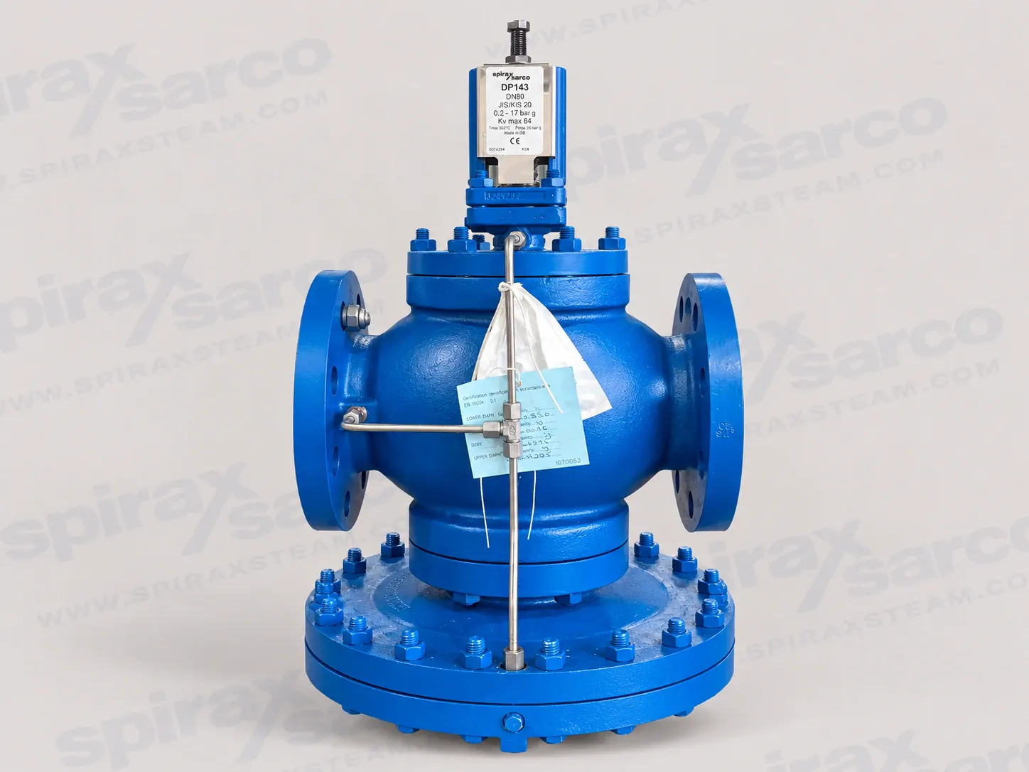
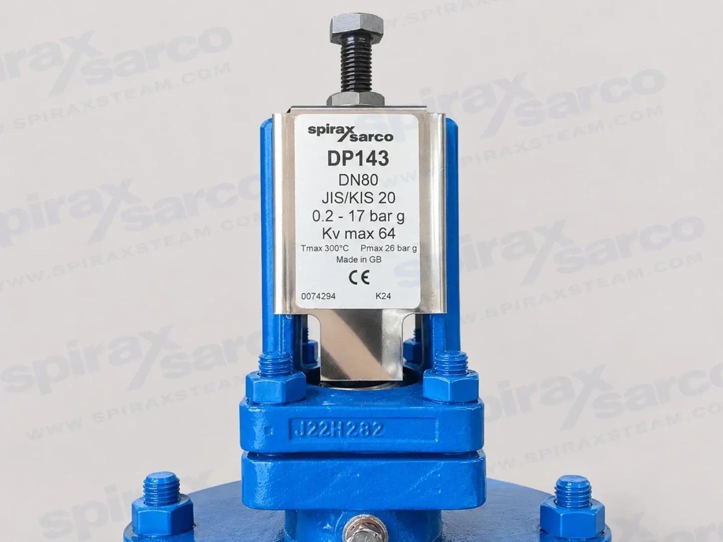
DP143-PRESSURE-REDUCING-VALVE
DP143 Pilot Operated Pressure Reducing Valve
DP143 is a pilot operated pressure reducing valve with a cast steel body for steam service, documented in sizes from DN15LC to DN80 with selectable downstream spring ranges from 0.2 to 24 bar g.
DP143 Pilot Operated Pressure Reducing Valve
Spirax Sarco DP143 is a pilot operated pressure reducing valve with a cast steel body for steam service. It is intended for pressure reduction stations where the downstream pressure must be controlled against changing steam demand, and where the valve, sensing arrangement and surrounding protection need to be selected as one system. The pilot circuit uses downstream pressure feedback to control the main valve, allowing the DP143 to handle the documented size and pressure range with a more controlled response than a simple manual throttling valve.
This page covers the DP143 model only. The documented size family includes DN15LC low capacity, DN15, DN20, DN25, DN32, DN40, DN50 and DN80. The local specification table contains exact complete-unit records for DN15 through DN80; DN15LC remains a documented technical size but is not presented as a priced enquiry option because no exact complete-unit row was found in the current price reference. Final selection must always be checked against the actual steam flow, upstream pressure, required downstream pressure, connection standard and safety requirements.
How the DP143 controls steam pressure
A pilot operated regulator does not control the whole pressure drop through the adjustment spring alone. The DP143 combines the pilot valve, control pipework, main diaphragm chamber, main valve and balance pipe so that a change in downstream pressure changes the pilot control condition and, in turn, the opening of the main valve. This arrangement gives the engineer a defined route for setting the downstream pressure and for diagnosing a pressure problem through upstream and downstream gauges.
The internal balance pipe is suitable for the normal arrangement described by the manufacturer, but it is not equivalent to a carefully positioned external sensing line in every duty. The technical information warns that reliance on the internal balance pipe can reduce capacity, with a possible reduction of up to about 30 percent of valve capacity at low downstream pressure. For closer control, improved stability or maximum-capacity conditions, the installation guide requires the balance pipe to be replaced by an external pressure sensing pipe. The sensing point and its straight-pipe lengths are therefore part of the DP143 selection, not an afterthought.
Where the DP143 fits in a steam pressure station
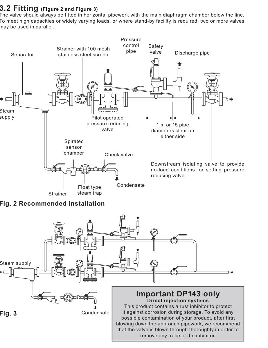
The DP143 is useful where a steam supply must be reduced to a controlled pressure for equipment or a process area. Typical duties include a branch serving heat-transfer equipment, a plant distribution header feeding lower-pressure users, and a process station where the downstream pressure must remain within a defined spring range as demand changes. A complete station normally includes upstream isolation, a same-size strainer, steam separation and drainage, pressure gauges, downstream isolation and a safety valve. The valve should not be selected as a stand-alone replacement for the complete pressure-control arrangement.
Steam quality matters. The installation instructions recommend that the valve be supplied with dry steam and identify a separator as the ideal upstream arrangement. If the downstream pipework can flood when the downstream isolation valve is closed, a trap set is needed to remove condensate caused by radiant losses. These provisions protect the control system from wet steam, dirt and accumulated condensate, all of which can make a correctly sized valve appear unstable or unable to maintain the set pressure.
Size, connection and capacity considerations
The standard DP143 flange choices are EN 1092 PN40, BS 10 Table J and ANSI 300. ANSI 150 and JIS 20 connections are available on request according to the technical information. The eight documented technical sizes run from DN15LC to DN80, and the steam capacity chart provides a separate capacity scale for each size. Nominal pipe size alone is not a sizing method: the required mass flow, upstream pressure, downstream pressure and available differential pressure must be located on the chart together.
The maximum Kv values are 1.0 for DN15LC, 2.8 for DN15, 5.5 for DN20, 8.1 for DN25, 12.0 for DN32, 17.0 for DN40, 28.0 for DN50 and 64.0 for DN80. The technical information describes these as full-capacity values and says they should be used for safety-valve sizing purposes only. The steam capacity chart is read by finding the intersection of the upstream-pressure curve and the required downstream-pressure line, then reading the capacity scale for each size. This makes it possible to identify the smallest size that meets the load without assuming that the valve should match the upstream line size.
For superheated steam, the chart result needs a correction for the higher specific volume. The published factors are 0.95 for 55 °C of superheat and 0.90 for 100 °C of superheat. In the technical example, a DN32 valve carrying 740 kg/h of saturated steam at the chart condition becomes 703 kg/h after the 0.95 correction. If the actual steam condition, load or pressure ratio differs materially from the chart assumptions, an engineering sizing review should be obtained before the order is placed.
Pressure, temperature and spring selection
The DP143 body has a PN40 design condition. For the standard flange group, the maximum upstream pressure for saturated steam is 26 bar g and the maximum differential pressure is 26 bar. For the ANSI 150 flange condition, both values are limited to 14 bar. The model maximum operating temperature is 300 °C at 26 bar g, while the minimum operating temperature is 0 °C. The wider design data lists a maximum design temperature of 350 °C at 24 bar g, so design, operating and test conditions must not be mixed when the station is specified.
Two standard colour-coded pressure adjustment springs are available for DP143. The red spring covers downstream pressures from 0.2 to 17 bar g and the grey spring covers 16.0 to 24 bar g. The overlap should be considered when choosing the spring for controllability. A pressure setting at the edge of a spring range deserves particular attention during commissioning, especially when steam load varies widely. The cold hydraulic test pressure is 60 bar g, but the technical information limits testing to 40 bar g once the internal parts are fitted.
Installation planning before the valve arrives
The valve is installed in a horizontal pipeline with the main diaphragm chamber below the line and with the body arrow aligned to the steam flow. Pipework on both sides must be sized so that velocity does not exceed 30 m/s, and pipe expansion or inadequate support must not impose stress on the cast steel body. A same-size upstream strainer with a 100 mesh screen should be fitted on its side to prevent water accumulation. The downstream side needs a pressure gauge for setting; an upstream gauge is an important diagnostic instrument.
When an external sensing pipe is required, the connection should be made at the top of the reduced-pressure main wherever practicable. In either direction from the sensing point, the guide requires at least 1 m or 15 pipe diameters of uninterrupted straight pipe, whichever is greater. The sensing pipe should have a positive fall so condensate drains away from the DP143. A downstream safety valve must protect the equipment from excessive pressure, and its set pressure must account for the no-load setting, blowdown and an additional safety margin.
Commissioning, maintenance and ordering checks
Commissioning starts with all connections made and all valves closed. The adjustment spring is slackened, the control line is opened, the approach pipework is blown through and the upstream isolation valve is opened slowly. The adjustment screw is then turned gradually until the downstream gauge shows the required pressure; the lock-nut is secured before the downstream valve is opened slowly. Where two valves are used in parallel, each valve is set independently against dead-end conditions, with the smaller valve set about 0.1 bar higher than the larger valve.
The manufacturer recommends a complete overhaul every 12 to 18 months, ideally with the valve removed from the line. Maintenance includes checking the main valve and seat, pilot assembly, pilot diaphragms, main diaphragms, pushrod liner, control pipework and balance pipe. Before any work, the valve must be isolated, pressure must be reduced safely to zero and hot surfaces must be allowed to cool. Control orifices must be kept clear without enlarging them, because their dimensions influence the control response.
When ordering Spirax Sarco DP143, state the nominal size, flange standard, upstream and required downstream pressure, spring range, steam condition, flow requirement and any certification or inspection requirement. The technical information confirms that EN 10204 3.1 certification is available when requested at the time of order. The current enquiry options list the exact DP143 complete-unit records for DN15, DN20, DN25, DN32, DN40, DN50 and DN80 with their material codes.
Why choose the DP143 route
Spirax Sarco DP143 provides a documented pilot operated steam pressure reduction route with a cast steel body, broad size coverage, two standard downstream spring ranges and published capacity information. Its performance depends on the entire station: correct sizing, dry steam, clean trim, suitable pressure sensing, safe downstream protection and disciplined commissioning. Confirm those conditions together before purchase so that the selected DP143 configuration matches the real steam duty rather than only the line size.
Product description
DP143 is a pilot operated pressure reducing valve manufactured with a cast steel body for steam applications. The valve is available in DN15LC low capacity, DN15, DN20, DN25, DN32, DN40, DN50 and DN80 sizes.
The standard flange connections are EN 1092 PN40, BS 10 Table J and ANSI 300. ANSI 150 and JIS 20 connections are available on request. The product complies with the requirements of EU Pressure Equipment Directive 2014/68/EU and EN 10204 3.1 certification is available when the certification and inspection requirement is stated at order placement.
Pressure and temperature limits
| Item | DP143 limit or condition |
|---|---|
| Body design condition | PN40 |
| Maximum design pressure, ANSI 150 group | 18.9 bar g at 20 °C |
| Maximum design pressure, standard flange group | Limited to 26 bar g |
| Maximum design temperature | 350 °C at 24 bar g |
| Minimum design temperature | 0 °C |
| Maximum upstream pressure for saturated steam, standard flange group | 26 bar g |
| Maximum upstream pressure for saturated steam, ANSI 150 group | 14 bar g |
| Maximum operating temperature | 300 °C at 26 bar g |
| Minimum operating temperature | 0 °C; consult the manufacturer for lower temperatures |
| Maximum differential pressure, standard flange group | 26 bar |
| Maximum differential pressure, ANSI 150 group | 14 bar |
| Maximum cold hydraulic test pressure | 60 bar g |
| Test pressure with internals fitted | Must not exceed 40 bar g |
Pressure adjustment springs
| Spring colour | Downstream pressure range |
|---|---|
| Red | 0.2 bar g to 17 bar g; the source spare-parts notation also states 0.2 to 17 bar |
| Grey | 16.0 bar g to 24 bar g; often shown as 16 to 24 bar in the source spare-parts table |
The spring should be selected against the required downstream pressure and the actual operating range. The overlap between the two ranges must be considered when choosing the spring for control.
Materials of construction
| Part | Component | Material or specification |
|---|---|---|
| 1 | Adjustment screw | Steel, BS 3692 Grade 8.8 |
| 2 | Adjustment lock-nut | Steel, BS 3692 Grade 8 |
| 3 | Washer | Stainless steel, BS 1449 304 S16 |
| 4 | Spring housing | Cast steel, DIN 17245 GS C25 |
| 5 | Top spring plate | Stainless steel, BS 970 220 Mo7 |
| 6 | Pressure adjustment spring | Stainless steel, BS 2056 302 S25 |
| 7 | Bottom spring plate | Stainless steel, EN 10088-3 1.4057 |
| 8 | Spring housing securing parts | Steel, BS 4439 Grade 8.8; studs M10 x 30 mm for DN15 to DN80 |
| 9 | Pilot diaphragm | Stainless steel, BS 1449 316 S31 |
| 10 | Pilot valve housing | Steel; DIN 17245 GS C25 for DN15 to DN50, GP 240 GH+N for DN80 |
| 11 | Pilot valve plunger | Stainless steel, BS 970 431 S29 |
| 12 | Spring housing cover | Stainless steel, BS 1449 304 S12 |
| 13 | Pilot valve and seat unit | Stainless steel, BS 970 431 S29 |
| 14 | Internal strainer | Stainless steel, BS 1449 304 S16 |
| 15 | Body gasket | Stainless steel reinforced exfoliated graphite |
| 16 | Main valve return spring | Stainless steel, BS 2056 302 S16 |
| 17 | Main valve | Stainless steel, BS 970 431 S29 |
| 18 | Main valve seat | Stainless steel, BS 970 431 S29 |
| 19 | Balance pipe assembly | Stainless steel, BS 3605 304 S14 |
| 20 | Main valve body | Cast steel, DIN 17245 GS C25 |
| 22 | Main diaphragm chamber | Cast steel, DIN 17245 GS C25 |
| 24 | Main diaphragms | Stainless steel, BS 1449 316 S31 |
| 25 | Main diaphragm plate | Stainless steel, BS EN 10088-3 1.4307 |
| 26 | Push rod | Stainless steel, BS 970 431 S29 |
| 27 | Control pipe assembly | Stainless steel, BS 3605 304 S14 |
| 28 | Plug | Steel |
| 29 | Pressure pipe union | Steel |
| 30 | Lock-nut | Steel, BS 3692 Grade 8 |
| 21 | Pilot valve housing securing parts | Steel; M10 x 25 mm for DN15 and DN20, M12 x 30 mm for DN25 to DN50, M12 x 40 mm for DN80 |
| 23 | Main diaphragm chamber securing parts | Steel; M12 x 50 mm for DN15 and DN20, M12 x 60 mm for DN25 and DN32, M12 x 65 mm for DN40 and DN50, M12 x 80 mm for DN80 |
| 45–46 | Body studs, nuts and upper chamber | Steel, BS 4439 Grade 8.8 studs and BS 3692 Grade 8 nuts; upper chamber cast steel 1.0619+N |
Dimensions and approximate weights
Dimensions are in mm and weights are in kg. The four A columns correspond to EN 1092 PN40, ANSI 300, ANSI 150 and BS 10 Table J flange arrangements.
| Size | A EN 1092 PN40 | A ANSI 300 | A ANSI 150 | A BS 10 Table J | B | D | E | F | Weight |
|---|---|---|---|---|---|---|---|---|---|
| DN15LC | 130 | 130 | 122 | 130 | 175 | 405 | 277 | 128 | 15 |
| DN15 | 130 | 130 | 122 | 130 | 175 | 405 | 277 | 128 | 15 |
| DN20 | 150 | 150 | 142 | 150 | 175 | 405 | 277 | 128 | 16 |
| DN25 | 160 | 160 | 156 | 164 | 216 | 440 | 288 | 152 | 23 |
| DN32 | 180 | 183 | 176 | 184 | 216 | 440 | 288 | 152 | 25 |
| DN40 | 200 | 209 | 200 | 209 | 280 | 490 | 305 | 185 | 40 |
| DN50 | 230 | 236 | 230 | 243 | 280 | 490 | 305 | 185 | 42 |
| DN80 | 310 | 319 | 310 | 325 | 350 | 580 | 322 | 258 | 103 |
Kv values and steam capacity
| Size | DN15LC | DN15 | DN20 | DN25 | DN32 | DN40 | DN50 | DN80 |
|---|---|---|---|---|---|---|---|---|
| Kv | 1.0 | 2.8 | 5.5 | 8.1 | 12.0 | 17.0 | 28.0 | 64.0 |
For conversion, Cv (UK) = Kv x 0.963 and Cv (US) = Kv x 1.156. The steam capacity chart is used by locating the intersection of the upstream pressure curve and the downstream pressure line, then reading the size capacity scale. Capacity figures are based on an external pressure sensing pipe; the internal balance pipe can reduce capacity by up to 30% in the low-downstream-pressure case described by the source.
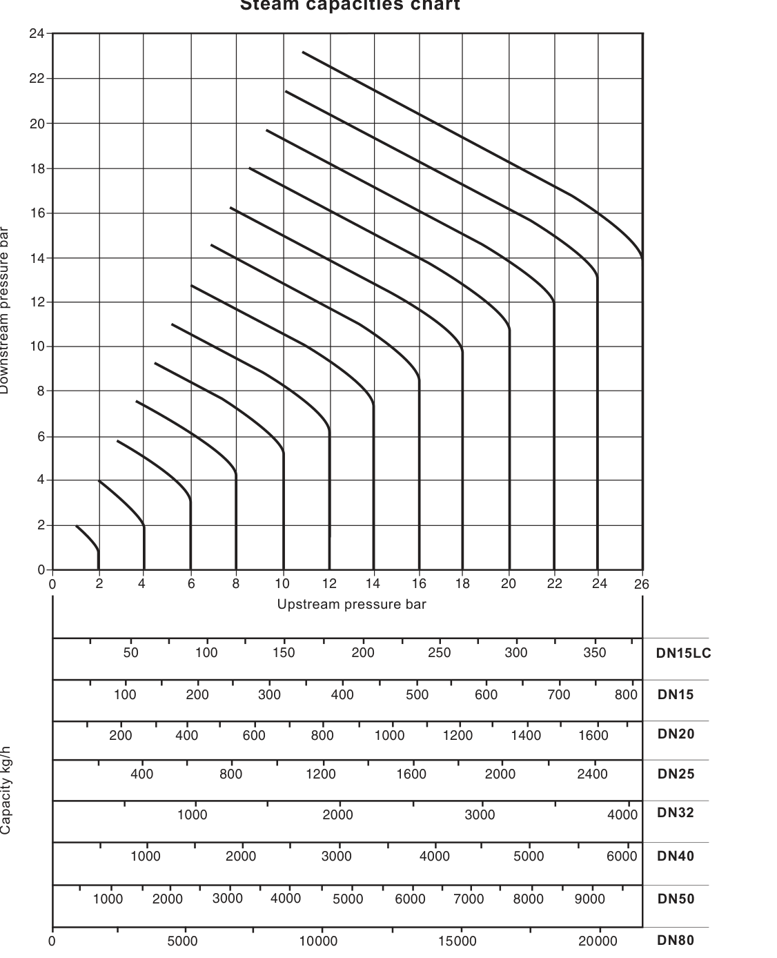
For saturated steam, the source example finds a 600 kg/h duty reducing from 6 bar to 4 bar and identifies DN32 as the smallest size meeting that load. For superheated steam, apply a correction factor of 0.95 at 55 °C of superheat or 0.90 at 100 °C of superheat to the saturated-steam chart result; the source example gives 703 kg/h after applying the 0.95 factor to 740 kg/h.
Available spare parts
Available spare groups include main diaphragms, pilot diaphragms, the pilot valve seal assembly, pilot valve and plunger assembly, main valve assembly, main valve return spring, pressure adjustment spring, control pipe assembly, balance pipe assembly, body gasket, spring housing securing sets, pilot valve housing securing sets, diaphragm chamber securing sets, DN80 body stud and nut sets, and the push rod and main diaphragm plate assembly.
When ordering spares, state the valve size, DP143 model and pressure rating, and use the description in the available-spares list. A maintenance kit is a standby set covering the marked general-maintenance spare groups; it is not a product specification option.
Safety, installation and maintenance reference
Install the DP143 in a horizontal pipeline with the main diaphragm chamber below the line and follow the flow arrow on the body. For complete safety information, installation, commissioning and maintenance instructions, use the accompanying IM-P006-07 installation and maintenance document supplied with this product.
Safety information
Safe operation is guaranteed only when the DP143 is installed, commissioned, used and maintained by qualified personnel in accordance with the operating instructions and general pipeline safety practice. Before work begins, verify that the product is suitable for the intended application using the nameplate and technical information.
- This DP143 page is limited to steam service. If another fluid is contemplated, confirm the suitability of the specific product, materials, pressure and temperature conditions with the manufacturer.
- Check material suitability, pressure and temperature, including maximum and minimum values. If the product limits are lower than the system limits, provide a safety device to prevent overpressure or overtemperature.
- Determine the correct installation position and fluid-flow direction. The installer must minimise external stresses from expansion, poor support or misalignment.
- Provide safe access, lighting, lifting equipment and protective clothing appropriate to the fluid, temperature, pressure and work environment.
- Before dismantling, isolate and safely vent pressure. Do not assume that a zero gauge reading proves that the system is depressurised. Allow hot surfaces to cool.
- Protect the product from frost where it is not self-draining. Use genuine replacement parts and follow the applicable permit-to-work system.
At maximum permitted operating conditions, product surfaces may reach about 300 °C. Residual fluid can remain inside the valve and pipework after isolation, so drain and handle the assembly with care.
Product information
The DP143 is a cast steel pilot operated pressure reducing valve for steam. The documented sizes are DN15LC low capacity, DN15, DN20, DN25, DN32, DN40, DN50 and DN80. Standard flanges are EN 1092 PN40, BS 10 Table J and ANSI 300 (also named ASME 300 in the installation source); ANSI 150 (ASME 150 in the installation source) and JIS 20 are available on request. Refer to the technical information for pressure, temperature, spring and capacity limits before installation.
The current technical information defines the standard flange group as EN 1092 PN40, ANSI 300 and BS 10 Table J. An older installation-guide table also mentions EN 1092 PN25; the current technical-information revision is used for this product page, so PN25 is not treated as a current DP143 standard option without manufacturer confirmation.
Installation position and supply
Install the DP143 in a horizontal pipeline with the main diaphragm chamber below the line. Follow the arrow on the valve body for flow direction. Two or more valves may be installed in parallel where capacity, load variation or standby service requires it.
The valve should be supplied with dry steam. A separator is the ideal arrangement in the steam supply. Where closing the downstream isolating valve can flood downstream pipework, fit a trap set to remove condensate formed by radiant heat loss.
Recommended installation arrangement
Pipeline sizing and stress
- Size pipework on both sides so that steam velocity does not exceed 30 m/s. A correctly sized valve may be smaller than the upstream pipework, while downstream pipework will often be larger.
- Do not impose line stresses caused by thermal expansion or inadequate support on the cast steel valve body.
- Use fullway isolating valves where practicable.
- Fit the upstream strainer in the same nominal size as the upstream pipework, with a 100 mesh screen. Fit it on its side to prevent water accumulation.
External pressure sensing
For closer control, improved stability or maximum-capacity conditions, replace the internal balance pipe with an external pressure sensing pipe supplied by others. Remove the balance pipe assembly, blank the unused body tapping with the supplied plug and connect the sensing pipe to the pilot chamber using the documented fitting arrangement.
Connect the sensing pipe into the top of the reduced-pressure main where practicable. In either direction from the connection, maintain at least 1 m or 15 pipe diameters of straight pipe without fittings, whichever is greater. Arrange the pipe with a positive fall so condensate drains away from the DP143. If a top connection cannot maintain the fall, a side connection may be used as described in the instructions.
Pressure gauges and downstream protection
A downstream pressure gauge is essential for setting the valve. An upstream pressure gauge is an essential diagnostic tool. Fit a downstream safety valve to protect equipment from excessive pressure. Set it below the safe working pressure of the protected equipment and size it for the possible full valve capacity if the reducing valve fails open.
The safety-valve set pressure must allow for the no-load pressure setting, the safety valve blowdown or reseat differential and a margin of at least 0.1 bar. The source gives a typical DIN safety-valve blowdown value of 10% of set pressure. Discharge pipework must lead to a safe place.
Bypass and adjacent control valves
If a continuous steam supply is essential while the DP143 is serviced, a bypass may be installed. The bypass is normally the same size as the reducing valve, its handwheel should be padlocked against unauthorised use and operation should remain under constant manual supervision. The bypass may be above or beside the assembly, never below it.
Install line or system isolation valves upstream. Where fast-acting downstream control equipment is used, keep it at least 50 pipe diameters from the DP143 to reduce the transmission of pressure pulses. If that distance is impractical, an intermediate vessel may provide a similar effect. Downstream pipework must be properly trapped so condensate cannot build up behind the valve.
Start-up and pressure setting
- Confirm that all connections are correctly made and all valves are closed.
- Turn the adjustment screw fully anticlockwise until the spring is slack.
- Open the small valve in the pressure control line.
- Blow through the approach pipework by removing and replacing the cap and screen from the strainer protecting the drain trap. Do not remove the screen from the main line strainer during this operation.
- Open the upstream isolating valve slowly until fully open.
- Using a 19 mm A/F spanner, turn the adjustment screw slowly clockwise until the required downstream pressure is shown on the gauge.
- Hold the adjustment screw, tighten the lock-nut and keep the C washer in position.
- Open the downstream valve slowly until fully open.
Inspect and clean the main line strainer at regular intervals. Do not treat a pressure setting obtained during a dirty or wet start-up as a stable commissioning result. The DP143 pressure and test limits include 26 bar g maximum saturated-steam upstream pressure for the standard flange group, 14 bar g for ANSI 150, 350 °C at 24 bar g maximum design temperature, 60 bar g maximum cold hydraulic test pressure and 40 bar g maximum with internals fitted. The ANSI 150 design point is 18.9 bar g at 20 °C.
Two valves in parallel
For parallel operation, a smaller valve can meet the lower load while a larger valve comes into operation for normal and maximum demand. Set each valve independently against dead-end conditions. Set the smaller valve approximately 0.1 bar higher than the larger valve, following the start-up sequence for each valve.
Direct injection systems
For a direct injection installation, the product contains a rust inhibitor to protect it during storage. After first blowing down the approach pipework, blow through the valve thoroughly to remove any trace of the inhibitor and avoid possible contamination of the product or process.
Routine maintenance
Before starting maintenance, observe all safety information, isolate the reducing valve and confirm that upstream and downstream pressures are zero. A complete overhaul is recommended every 12 to 18 months, ideally with the valve removed from the line.
Parts that may require replacement or refurbishment include the main valve and seat, pilot valve assembly, pilot diaphragms and main diaphragms. Clean the pushrod liner bush, control pipework, fittings and balance pipe when scale or dirt is present. Keep control orifices clear; do not use a drill because enlarging an orifice can upset operation.
If diaphragms are removed but not renewed, refit them in exactly the same orientation. The body gasket contains a thin stainless steel support ring that can cause injury if handled or disposed of incorrectly.
Pressure adjustment springs
DP143 adjustment springs are colour coded. The red spring covers 0.2 bar g to 17 bar g and the grey spring covers 16.0 bar g to 24 bar g. To change the control spring, slacken the adjustment screw, remove the C washer and cover, replace the spring and top plate, then refit the cover and reset the downstream pressure. Isolation is not required for the spring change itself, but the pressure and hot-surface hazards still require a controlled procedure.
Pilot valve assembly and strainer
To service the pilot valve assembly, isolate the valve, slacken the spring, remove the spring housing components and release the 6 mm stainless steel control pipework. Remove the pilot valve housing and use the documented 27 mm A/F socket for the pilot valve assembly and a 24 mm A/F socket for the bellows seal assembly. The plunger and bellows seal must be checked with the specified 0.7 mm clearance using a straight edge. Tightening torque for the pilot valve assembly and bellows seal is 115 N m.
To clean the pilot strainer screen, remove the pilot housing after isolation, retain the small return spring and ball, clean the screen and refit the parts. Tighten the screen retaining nut to 15 N m, renew the gasket where required, tighten the pilot housing securing nuts according to valve size and recommission the valve.
Main diaphragms, valve and seat
The main diaphragm diameters are 125 mm for DN15LC, DN15 and DN20; 166 mm for DN25 and DN32; 230 mm for DN40 and DN50; and 300 mm for DN80. When renewing the main diaphragms, isolate and depressurise the valve, remove the lower diaphragm chamber and replace the diaphragm plate and pushrod assembly with clean contact faces.
To service the main valve and seat, remove the control pipework and pilot valve block, remove the main valve spring and head, then remove the seat with the socket or special tool required for the valve size. If the lift is adjusted, use the specified lift values: 2.0 mm for DN15 and DN15LC, 2.5 mm for DN20, 3.0 mm for DN25, 3.5 mm for DN32, 4.5 mm for DN40, 5.0 mm for DN50 and 8.0 mm for DN80.
The recommended pilot valve block securing torques are 40 N m for DN15LC, DN15 and DN20 using M10 nuts, 60 N m for DN25 to DN50 using M12 nuts and 80 N m for DN80 using M12 nuts. The spring housing securing nuts are tightened to 50 N m, and the lower diaphragm chamber nuts and bolts are tightened to 75 N m.
| Size | Socket across flats | Tightening torque |
|---|---|---|
| DN15LC and DN15 | 30 mm A/F | 110–120 N m |
| DN20 | 36 mm A/F | 140–150 N m |
| DN25 | 41 mm A/F | 230–250 N m |
| DN32 | 46 mm A/F | 300–330 N m |
| DN40 | Not specified | 400–490 N m |
| DN50 | Not specified | 620–680 N m |
| DN80 | Not specified; special tool required | 600–700 N m |
Always use the complete size-specific procedure and verify that gasket faces, springs, heads and pipework are correctly positioned before recommissioning.
Spare parts and ordering
Available spare groups include main and pilot diaphragms, the pilot valve seal assembly, pilot valve and plunger assembly, main valve assembly, main valve return spring, pressure adjustment spring, control and balance pipe assemblies, body gasket, securing stud and nut sets, and the push rod and main diaphragm plate assembly.
Order spare parts using the description in the available-spares list and state the size, DP143 model and pressure rating. A maintenance kit covers the marked general-maintenance items. It is separate from the complete DP143 valve and must not be treated as a replacement product specification.
Fault finding
Before fault finding, isolate the valve and confirm that upstream and downstream pressures are zero.
Downstream pressure is zero or too low
- Confirm that high-pressure steam is reaching the valve and that the upstream strainer is clear.
- Check the pressure adjustment spring.
- Check the control pipe assembly and control orifice for blockage.
- Check the pilot and main diaphragms.
- Check that the valve capacity is sufficient for the downstream duty, that upstream pressure is correct and that the balance or external sensing pipe is installed correctly.
Downstream pressure is too high
- Check the external sensing pipe, control orifice and pilot diaphragm.
- Check whether the pilot valve, plunger, main valve or pushrod is sticking.
- Check main-valve seating and follow the documented servicing procedure.
Hunting or unstable pressure
- Confirm that upstream pressure is stable and that the upstream pipework is not restricted or undersized.
- Check the valve size against the full-load requirement.
- Check for wet steam and confirm the separator, trap and strainer arrangement.
- Confirm that the external sensing point is outside turbulent areas and that the pipework and moving parts are clean.
Documentation boundary
This installation and maintenance section is the DP143 scope of IM-P006-07. Use it together with the DP143 technical information, nameplate and site safety procedures. Do not apply a pressure, temperature, material or spring value from another model to DP143 without a separate manufacturer confirmation.