
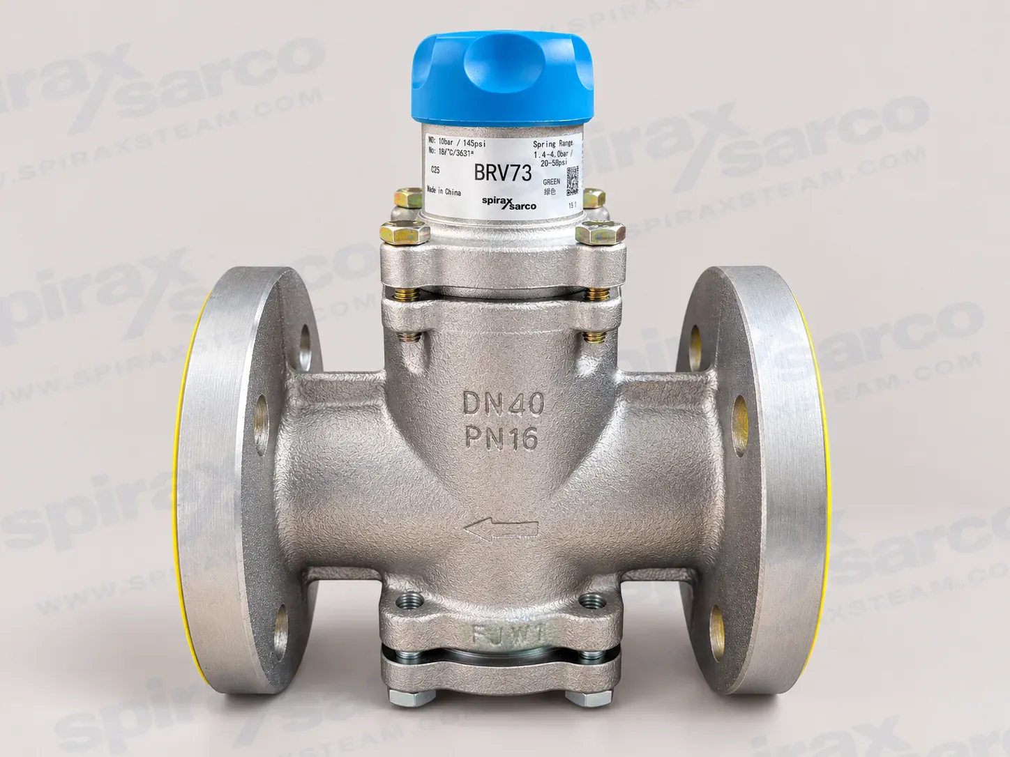
BRV73
BRV73 Direct Acting Pressure Reducing Valve
BRV73 is a ductile iron direct acting pressure reducing valve for steam, compressed air and inert industrial gases, with flanged PN16, JIS 10 or ANSI 150 connections, four DN sizes and three colour-identified spring ranges.
Spirax Sarco BRV73: Direct Acting Pressure Reducing Valve
Spirax Sarco BRV73 is a ductile iron, direct acting pressure reducing valve for controlled reduction of steam, compressed air and inert industrial gas pressure within the documented operating limits. It uses flanged connections and is available in DN25, DN32, DN40 and DN50 sizes. The flange options are PN16, JIS 10 and ANSI 150, so the connection standard can be matched to the surrounding pipework and plant specification. Three colour-identified control spring ranges make the available downstream pressure range visible at the adjustment handwheel.
Direct mechanical pressure control
BRV73 controls downstream pressure through a mechanical feedback path. Downstream pressure enters through a sensing hole in the stem and acts on the control bellows. That force is balanced against the compressed control spring, allowing the plug position to respond to changes in downstream conditions without an external power supply, electrical signal or instrument-air connection. A balance bellows reduces the effect of upstream and downstream pressure forces on the plug face, while graphite-filled PTFE bushes provide two-point guidance for the moving assembly.
The ductile iron body and bottom cover provide the documented body construction for the flanged valve. The principal internal working parts are stainless steel, the spring chamber is aluminium and the valve includes a stainless steel internal strainer. These material statements describe the official construction; process compatibility still has to be checked against the actual medium, temperature, pressure and contaminants before selection.
Flange and size selection
Start selection with the required flow, upstream pressure, target downstream pressure and available pressure drop. Then confirm the nominal DN size and flange standard. BRV73 is the flanged configuration, and its documented sizes are DN25, DN32, DN40 and DN50. PN16, JIS 10 and ANSI 150 flange dimensions differ, so the mating flange standard and face-to-face space should be confirmed before an order is placed. The published dimensions and approximate weights should be used for layout and support checks, not as a substitute for checking the actual valve and gasket arrangement.
The valve should be sized from the service duty rather than selected only by the pipe nominal diameter. The fully open Kv values are 9.3 for DN25, 11.1 for DN32, 15.7 for DN40 and 16.2 for DN50. If a Cv value is required, the documented conversions are Cv (UK) = Kv x 0.963 and Cv (US) = Kv x 1.156. Use the sizing chart with the upstream and downstream pressure curves, then verify the result against the required mass flow and the actual medium.
Spring ranges and downstream set pressure
BRV73 is supplied with one of three colour-identified control springs. The spring range must cover the required downstream setting, and the marking on the adjustment handwheel should be checked before commissioning. Where two ranges overlap, the lower range spring is recommended for better control.
| Spring identification | Documented downstream control range | Selection note |
|---|---|---|
| Grey | 0.14-1.7 bar g | Use the lower range when the required setting overlaps another range. |
| Green | 1.40-4.0 bar g | Confirm the target downstream setting is within the range. |
| Orange | 3.50-9.0 bar g | The maximum documented downstream setting is 9 bar g. |
Pressure, temperature and reduction limits
The exact BRV73 technical information specifies a PN16 body design condition. The maximum allowable pressure is 16 bar g at 120 °C, while the maximum allowable and operating temperature is 184 °C at 10 bar g. The maximum operating pressure for saturated steam is 10 bar g, the maximum downstream set pressure is 9 bar g and the maximum operating differential pressure is 10 bar. At maximum flow, the recommended maximum pressure reduction ratio is 10:1. The minimum allowable temperature is -10 °C and the minimum operating temperature is 0 °C; consult the manufacturer for operation below that temperature.
These figures are conditional operating limits, not independent ratings that can be combined without checking the duty. Pressure, temperature, medium, spring range, flow and pressure ratio must be reviewed together. The design cold hydraulic test pressure is 24 bar g, but after the internal components have been fitted the test pressure must not exceed 16 bar g. The surrounding system must include suitable protection against pressure or temperature above the documented limits.
Applications and practical boundaries
BRV73 is suited to steam pressure reduction at process branches, utility lines and other points of use where a self-acting mechanical regulator meets the required capacity and control range. The installation guide identifies steam, compressed air and inert industrial gases as intended media. It does not establish a universal approval for every fluid, mixture or hazardous service. Confirm the material compatibility, pressure equipment classification, local regulations and temperature conditions for the actual installation.
Direct acting control is useful where a simple, self-contained pressure-reducing arrangement is preferred. The same simplicity makes correct sizing and installation important. The upstream pressure, downstream set pressure, expected flow, reduction ratio, spring colour, flange standard, nominal size and maintenance access should be settled before the purchase order. For a different published pressure-reducing arrangement, the 25P pressure reducing valve page provides a separate comparison path. A compact selection can be compared with the published BRV2S pressure reducing valve page. Where the project requires a pilot-operated pressure reducing valve, see the DP27 pressure reducing valve page rather than treating BRV73 as a substitute for that control architecture.
Installation and commissioning checks
Install BRV73 horizontally and follow the arrow on the body for flow direction. The installation guide recommends locating upstream and downstream isolation valves 8-10 pipe diameters from the valve. Pipework must be adequately sized to avoid excessive pressure loss, eccentric reducers should be used where a line changes size, and pipe expansion or inadequate support must not transfer external stress into the valve body.
Protect the valve with an upstream filter mounted on its side so that collected water does not reduce the effective filter area. For wet steam, install a separator and trap set, or a suitable drain point and trap. An upstream gauge helps check supply pressure and a downstream gauge is important for setting the reduced pressure. A downstream safety valve protects the downstream system; its reseating pressure must have enough margin from the BRV73 set pressure to avoid unstable operation.
Before adjustment, flush the pipework to remove dust, excess jointing material and other debris. Open the upstream isolation valve fully while the downstream valve remains closed, then turn the handwheel clockwise to raise downstream pressure gradually to the target shown on the gauge. Open the downstream isolation valve slowly and recheck the setting under normal flow. Once the desired pressure is reached, use the coloured spring-range disc and locating pin to prevent unauthorised adjustment, following the installation and maintenance instructions.
Maintenance and ordering information
Keep the plug and seat clean, and periodically clean both the upstream filter and the valve's internal strainer to prevent flow restriction. Before maintenance, isolate the valve, release pressure safely and allow hot surfaces to cool. The seat is permanently installed in the body; if it is damaged, the body must be replaced. The documented spare groups include the three control springs, stainless steel control bellows, the bellows and pushrod assembly, bottom cover, strainer, gasket set, bolt sets and return spring. Maintenance work must be performed by qualified personnel using suitable tools and the documented sequence.
When ordering, state BRV73, the nominal DN size, the flange standard, the spring colour and required downstream pressure range. Confirm the upstream pressure, steam or gas service, expected flow, temperature, pressure ratio and the space needed for removal and adjustment. Spirax Sarco BRV73 should be selected against the complete operating case, not only the pipe size or the colour on the handwheel. With those checks complete, the valve provides a compact flanged direct acting pressure reducing solution within the exact pressure, temperature and flow limits documented for BRV73.
Product description
BRV73 is a ductile iron direct acting pressure reducing valve for steam systems, compressed air and inert industrial gases. It has flanged connections and is available in DN25, DN32, DN40 and DN50 sizes. Three coloured control spring ranges are available: grey, green and orange.
Downstream pressure is fed back through the stem sensing hole. Pressure acting on the control bellows is balanced against the compressed control spring. The balance bellows minimise the forces from upstream and downstream pressure on the plug face. Graphite-filled PTFE bushes in the pushrod/balance-bellows assembly and bottom-cover assembly provide two-point guiding.
Connections and spring ranges
| Item | BRV73 value |
|---|---|
| Connection | Flanged, PN16, JIS 10 or ANSI 150 |
| Sizes | DN25, DN32, DN40 and DN50 |
| Grey spring | 0.14-1.7 bar g |
| Green spring | 1.40-4.0 bar g |
| Orange spring | 3.50-9.0 bar g |
Where pressure ranges overlap, the lower range spring gives better control according to the technical information. Confirm the spring range shown on the adjustment handwheel against the required downstream pressure.
Pressure and temperature limits
| Symbol or item | Documented limit |
|---|---|
| Body design condition | PN16 |
| PMA maximum allowable pressure | 16 bar g at 120 °C |
| TMA maximum allowable temperature | 184 °C at 10 bar g |
| Minimum allowable temperature | -10 °C |
| PMO saturated steam maximum operating pressure | 10 bar g |
| TMO maximum operating temperature | 184 °C at 10 bar g |
| Minimum operating temperature | 0 °C; consult Spirax Sarco below this temperature |
| Maximum downstream set pressure | 9 bar g |
| PMX maximum operating differential pressure | 10 bar |
| Recommended maximum reduction ratio at maximum flow | 10:1 |
| Design cold hydraulic test pressure | 24 bar g |
After the internal components have been fitted, the test pressure must not exceed 16 bar g. Pressure and temperature limits must be checked together for the selected service.
Materials
| Part | Material | Specification or note |
|---|---|---|
| Body | Ductile iron | DIN 1693 GGG 40.3, ELNP coated |
| Control spring | Silicon chrome alloy | BS 2803 685 A55 |
| Adjustment screw | Carbon steel | BS 970 230 M07 |
| Flat washer | Stainless steel | Grade 18/10/3-4A |
| Adjustment handwheel | Nylon | 10B 140 |
| Locking pin | Stainless steel | AISI 420 |
| Spring plate | Cast iron | DIN 1691 GG 20 |
| Spring chamber | Aluminium | ELNP coated |
| Upper and lower washers | Semi-rigid laminated graphite | Gasket components |
| Control bellows and pushrod/balance-bellows assembly | Stainless steel | 316L or graphite-filled 316L as documented |
| Marking plate | Polypropylene | Spring range identification |
| Plug | Stainless steel | BS 970 431 S29, with EPDM O-ring |
| Strainer | Stainless steel | 316L |
| Bottom cover | Ductile iron | DIN 1693 GGG 40.3, ELNP coated |
| Bolts | Zinc-plated steel | BS 3692 Grade 8.8 |
| Bolt washer | Stainless steel | BS 1449 304 515 |
| Guide bushes | PTFE | 15% graphite filled |
| Return spring | Stainless steel | BS 2056 316 S42 |
| PTFE gasket | Pure PTFE | BS 6564 Type 2 Grade B |
| O-rings | EPDM | E 0962-90 |
Saturated steam and compressed air sizing
The source sizing chart uses the downstream pressure on the left vertical scale and curves labelled with the upstream pressure. Follow the required downstream pressure horizontally to the relevant upstream-pressure curve, then read the size and flow scale below the intersection. The chart includes separate steam and compressed-air flow scales; confirm the actual medium and operating condition before selecting a size.
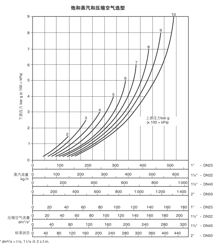
In the source example, a 350 kg/h requirement with pressure reduced from 8 bar g to 6 bar g is taken to the intersection of the 6 bar g downstream line and 8 bar g upstream curve. The chart indicates that the DN25 size meets that example condition. The example is not a substitute for sizing the actual installation.
Kv values
| BRV73 size | DN25 | DN32 | DN40 | DN50 |
|---|---|---|---|---|
| Kv | 9.3 | 11.1 | 15.7 | 16.2 |
Conversion: Cv (UK) = Kv x 0.963. Cv (US) = Kv x 1.156.
Flange dimensions and approximate weight
Dimensions are approximate and are in mm. Weight is in kg. The B dimension varies with the selected flange standard.
| Size | A | B PN16 | B ANSI 150 | B JIS 10 | C | D | E | G | Weight |
|---|---|---|---|---|---|---|---|---|---|
| DN25 | 134 | 174 | 170 | 170 | 67 | 153 | 90 | 84 | 5.90 |
| DN32 | 134 | 179 | 174 | 175 | 67 | 153 | 90 | 84 | 7.65 |
| DN40 | 134 | 186 | 183 | 180 | 67 | 153 | 90 | 84 | 8.55 |
| DN50 | 134 | 186 | 186 | 180 | 67 | 153 | 90 | 84 | 9.40 |
Installation direction and order information
Install BRV73 in a horizontal pipeline in the direction shown by the arrow on the body. When ordering, state the BRV73 model, nominal DN size, flange standard, stainless steel bellows requirement where applicable and the required spring range. Confirm the size, connection standard and spring range for the actual application.
For full safety, installation and maintenance requirements, use the separate installation and maintenance information that follows this technical section.
Installation and Maintenance Guide
- Safety information
- Product information
- Installation
- Start-up and adjustment
- Maintenance
- Spares
Document code: IM-P210-04
Issue: CH Issue 4
Product: BRV73 flanged pressure reducing valve
1. Safety information
Safe operation depends on installation, commissioning, use and maintenance by competent personnel in accordance with the operating instructions. Follow the applicable pipework, plant construction and safety requirements and use suitable tools and protective equipment.
Warnings
- When the valve is used on steam, the pressure adjustment handwheel can become hot. Wear protective gloves before adjusting it.
- Do not remove the valve from the installation before turning the adjustment handwheel counter-clockwise to release the force on the control spring.
- Handle the stainless steel reinforcement in gaskets carefully because it can cause cuts.
1.1 Preparation
Check the installation and maintenance guide, nameplate and technical information to confirm that BRV73 is suitable for the intended service. Check material safety, pressure and temperature limits, and their maximum and minimum values. If the product limit is lower than the system limit, or if a product fault could cause overpressure or overtemperature, provide suitable protective devices.
Confirm the correct installation position and flow direction. The valve must not be exposed to external stress generated by the installed pipework; the installer is responsible for supporting and routing the pipework to minimise such stress. Before installing a steam or other high-temperature service, remove connection protectors and any protective film from the nameplate.
1.2 Access, lighting and hazardous surroundings
Provide safe access and a safe working platform before operating the valve. Arrange suitable lifting equipment where needed and provide sufficient lighting, especially for complex work. Consider the contents and physical state of the pipework, including flammable or harmful substances, extreme temperatures, hot surfaces, ignition hazards, excessive noise and moving machinery.
1.3 Pressure, temperature and competence
Consider the effect of each operation on the complete system. Closing an isolation valve or isolating another service must not put another part of the system or personnel at risk. Isolate pressure and safely vent to atmosphere before maintenance. Consider double isolation, lock-out or tagging. A pressure gauge reading of zero is not proof that the system is depressurised.
After isolation, allow the valve to cool to a safe temperature to prevent burns and use protective clothing, including eye protection, where required. All work must be performed or supervised by competent personnel who understand the equipment and the site's formal permit-to-work and safety arrangements.
1.4 PTFE, other hazards, freezing and disposal
PTFE is inert within its normal temperature range but can decompose or burn at combustion temperatures and produce harmful fumes. Do not smoke where PTFE is handled, prevent contamination of clothing and wash hands after handling particles. During normal service the valve surface can be hot; at the maximum allowable operating temperature some surfaces can reach 210 °C. BRV73 has no self-draining function, so take care when removing it from pipework and provide protection against freezing where an installation can fall below the freezing point.
The product can be recycled when disposed of correctly. PTFE parts must be handled using an approved method and must not be incinerated. Keep PTFE waste in a separate container and do not mix it with general waste. When returning a product, provide information about any residue or mechanical damage that could create a health, safety or environmental hazard.
2. Product information
BRV73 is a direct acting pressure reducing valve for steam, compressed air and inert industrial gases. It is available in DN25, DN32, DN40 and DN50 flanged sizes. The flanges are available in PN16, ANSI 150 or JIS 10 standards. The body is ductile iron and the internal parts are stainless steel.
The valve adjusts by feeding downstream pressure back through a sensing hole in the stem. Pressure acting on the control bellows balances the compressed control spring. A balance bellows reduces the pressure force on the plug face and graphite-reinforced PTFE bushes provide two-point guidance. The maximum upstream pressure is 10 bar g and the recommended maximum pressure reduction ratio is 10:1.
| Spring colour | Pressure adjustment range |
|---|---|
| Grey | 0.14-1.7 bar g |
| Green | 1.40-4.0 bar g |
| Orange | 3.50-9.0 bar g |
The spring range is marked on the adjustment handwheel. Verify that the installed spring is correct for the application before adjustment.
3. Installation
Locate the upstream and downstream isolation valves 8-10 pipe diameters from each side of BRV73, leaving straight pipe between the isolation valves and the regulator. Do not apply pipe stress caused by thermal expansion or insufficient support to the valve body.
Size the upstream and downstream pipework sufficiently to avoid excessive pressure loss. Use eccentric reducers where a line changes size. Fit an upstream filter to protect the pressure reducing valve and mount it sideways so that collected water does not reduce the effective filter area. For wet steam, fit a separator and trap set, or a suitable drain point and trap. Fit a downstream pressure gauge to set the reduced pressure and an upstream gauge to check the supply pressure. Install a safety valve to protect the downstream system, leaving sufficient margin between its reseating pressure and the BRV73 set pressure.
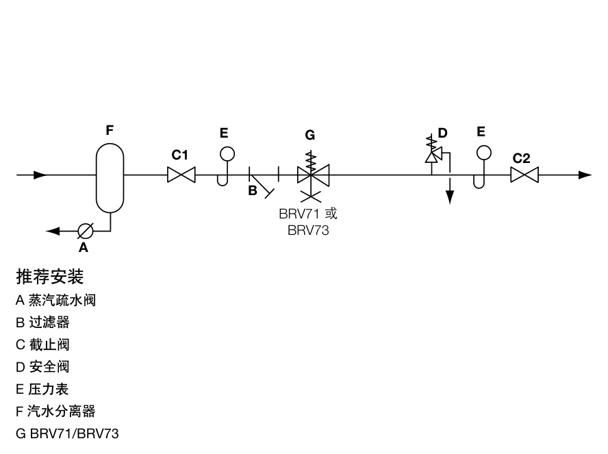
If installation or operation is difficult, contact Spirax Sarco or the local office before proceeding.
4. Start-up and adjustment
Before operating BRV73, thoroughly flush all pipework to remove dust, excess jointing material and other debris. Pressure adjustment is made by rotating the handwheel: clockwise increases pressure and counter-clockwise decreases pressure. Fully open the upstream isolation valve while the downstream isolation valve is closed. Turn the handwheel clockwise and raise downstream pressure slowly to the set pressure shown on the downstream gauge. Open the downstream isolation valve slowly. Under normal flow the set downstream pressure may fall slightly; re-adjust it if necessary. Under no-load conditions, the set pressure should be slightly higher.
Locking the set pressure
- When the required set pressure is reached, remove the coloured spring-range disc from the recess in the adjustment handwheel. Insert a small screwdriver beneath the disc to lift it.
- Remove the small locating pin stored in the handwheel recess.
- Insert the pin into locking hole A and into one of the ten holes in the top of the spring chamber to lock the pressure setting.
5. Maintenance
Keep the plug and seat clean. The upstream filter and the internal strainer in the valve should be cleaned regularly to prevent restriction in the flow path. Before dismantling, ensure that the adjustment handwheel is released, the valve is fully isolated and pressure has been safely discharged.
Removal
- Slowly loosen the four bottom-cover bolts and remove the return spring and gasket. The return spring is compressed; use the documented 17 mm A/F socket.
- Carefully remove the O-ring from the pushrod.
- Remove the lower pushrod and carefully remove the plug. Use the documented long-reach 15 mm A/F tool.
- From the top of the valve, loosen and remove the four spring-chamber bolts. Use the documented 13 mm A/F socket.
- Remove the spring chamber and control spring.
- Remove the control bellows, gasket, balance-bellows/pushrod assembly and gasket.
- Remove the internal strainer.
- The seat is permanently fitted in the body. Clean it by lapping before reassembly; if the seat is damaged, replace the body.
Reassembly
- Ensure the strainer is clean and install it with the conical face down and the joint away from the inlet.
- Fit the gasket into the body.
- Install the bellows and pushrod assembly with the pushrod facing down.
- Install the gasket and control-bellows assembly.
- Install the control spring on the bellows assembly.
- Fit the spring chamber to the valve body and ensure the flanges align correctly.
- Install the four spring-chamber bolts and tighten to 18/24 N m with a torque wrench.
- Ensure the O-ring is fitted in the plug and the plug recess is clear of the lower pushrod hexagon. Screw the lower pushrod fully into the pushrod/bellows assembly, then back it off by one quarter turn so the plug can move.
- Fit the O-ring in the lower pushrod groove.
- Fit the gasket into the body.
- Install the return spring in the plug.
- Fit the return spring in the bottom cover and ensure the cover matches the body.
- Compress the bottom cover and install two bolts to retain it.
- Install the remaining bolts and tighten all bottom-cover bolts to 20/26 N m with a torque wrench.
Check that the adjustment handwheel moves freely before returning the pressure reducing valve to service.
Recommended tightening torque
| Location | Torque |
|---|---|
| Spring-chamber bolts | 18/24 N m |
| Bottom-cover bolts | 20/26 N m |
6. Spares
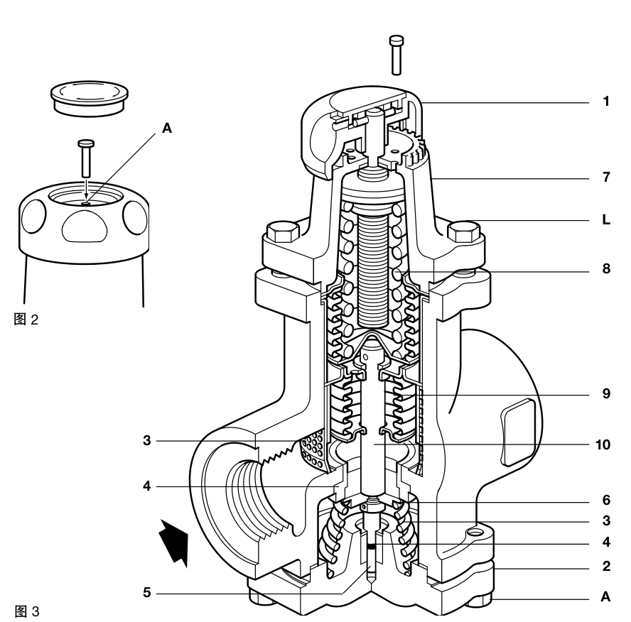
Spares are shown by solid lines in the source figure; dashed components are not supplied as spares. The documented spare groups are common to the available sizes.
| Spare group | Detail |
|---|---|
| Control spring | Grey 0.14-1.7 bar g; green 1.40-4.0 bar g; orange 3.50-9.0 bar g |
| Control bellows | Stainless steel |
| Bellows and pushrod assembly | Includes the plug, O-ring, lower pushrod and PTFE gasket as documented |
| Bottom cover | BRV73 bottom-cover assembly |
| Strainer | Internal strainer |
| Gasket set | Documented gasket group |
| Bolt sets | Spring-chamber and bottom-cover bolt sets |
| Return spring | Bottom-cover return spring |
When ordering spares, state the valve size, model and pressure range. Before any work on the valve, ensure that it is completely isolated.
Sales brochures
| Document | Reference | Language | Download |
|---|---|---|---|
| pressure reducing and surplussing valves | SB-GCH-29-EN | English | Download |