
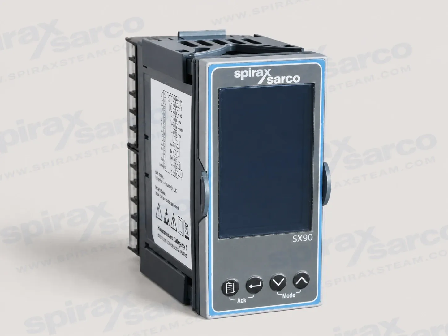
SX90 process controller for panel-mounted PID control
The Spirax Sarco SX90 is a 1/8 DIN panel-mounted universal-input PID process controller for industrial temperature and pressure control. It accepts a wide range of process signals, applies configurable PID control, and provides outputs for modulating equipment, alarms, retransmission and logic functions. The controller is designed to work with pneumatic or electric control valves and with the electronic and electrical instruments that complete a process control loop. For a project searching for a Spirax Sarco SX90 process controller, the central selection task is to match the measured variable, control response, output arrangement and panel installation to the actual plant.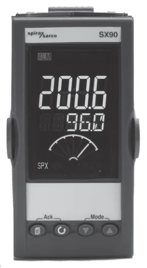
Flexible process signal path
The SX90 process controller has a universal process-variable input. Depending on the configured application, the input can accept a three-wire Pt100 RTD, thermocouples of types K, J, N, R, S, B, L, T and C, a custom thermocouple, a 4-20 mA or 0-20 mA linear signal, or a -10 to 80 mV signal. This lets one panel format serve temperature instruments and transmitter-based pressure or other process measurements without adding a separate signal converter for every input type. The mA input uses the supplied 2.49 ohm shunt resistor as shown in the wiring information, so the complete signal circuit must be checked before commissioning.
The controller can work with three local setpoints and a remote setpoint. A remote setpoint signal can be supplied as 0-10 V or 0-20 mA, allowing the operating target to be set from another control layer. The documented cascade function uses a remote setpoint to coordinate two controllers in a master/slave arrangement. This makes the SX90 useful where the local loop needs a stable target from a supervisory or upstream process loop, while keeping the controller's own input, output and alarm configuration close to the equipment being controlled.
Control functions that suit changing process demand
PID control gives the SX90 a way to respond to process error rather than simply switch at one threshold. Proportional, integral and derivative settings can be adjusted for the process dynamics, and automatic tuning can select control parameters from the observed process response. The controller also supports automatic, manual and off modes. Manual mode is useful during commissioning or controlled fault-finding, but the output level and the effect on the plant remain the responsibility of the authorised commissioning person.
Setpoint ramping provides separate rising and falling rate limits when the process should move between targets at a controlled rate. The SX90 can use an automatic or manual setpoint, a remote setpoint and event alarms for deviation, band or process-value conditions. Three logic inputs provide selectable functions such as automatic/manual selection or alarm acknowledgement. Text messages can be configured for operator prompts, and a force-output function can be activated through a logic input or parameter where the configured instrument settings permit it. These functions are useful for commissioning and operating visibility, but they do not replace an independent protective trip or a site safety system.
Outputs for valves, alarms and control-system integration
The output hardware is arranged for more than one type of final control action. The standard output set includes a normally open relay, configurable analogue outputs and an SX90-specific changeover relay. Outputs 5 and 6 are interlocked normally open relays for VMD valve-motor drive operation. Depending on the quick-code configuration, the available outputs can be assigned to VMD control, continuous current or voltage functions, alarm relays, logic or retransmission. The exact quick code must therefore be selected from the required valve, actuator and alarm arrangement rather than inferred from the product name alone.
OP2 and OP3 can provide 0-20 mA or 4-20 mA analogue signals. The relay contacts are rated for a maximum 2 A at 264 Vac resistive load, with the terminal and load restrictions in the wiring instructions applying to the installed circuit. A potentiometer input accepts a 100-10 kOhm feedback potentiometer and can be used where the valve position needs to be brought into the control arrangement. An isolated remote-setpoint input accepts either voltage or current. The built-in RS485 five-wire interface is compatible with EIA422 wiring and Modbus RTU slave operation, with the technical sheet documenting connection of up to 64 controllers to a management system.
Panel fit and operating boundary
The SX90 is intended for permanent indoor installation in an electrical panel. Its approximate envelope is 48 mm wide, 96 mm high and 101 mm deep; the technical drawing also identifies a 90 mm rear-body dimension. The recommended panel cutout is 45 mm by 92 mm with the stated manufacturing tolerances. The front panel is rated IP65 when inserted through the panel and is identified as NEMA 4X in the exact-model technical sheet. These front-panel ratings do not remove the need for a suitable enclosure, clean wiring practice and protection from condensation, conductive pollution, vibration and electrical interference.
The documented supply range is 85-265 Vac with maximum power consumption of 9 W. The stated operating environment is 0-55 deg C and 5-85% relative humidity. The SX90 is not suitable for explosive or corrosive atmospheres. The installation guide additionally treats it as an indoor panel instrument and identifies an upper altitude boundary of 2000 m for the general product-family application. Where a process can overheat after a control fault, fit an independent overtemperature protection device; the controller's alarm relays are not a substitute for protection under every failure condition.
Selection checks before ordering
Start by defining the process variable and its complete signal path: sensor or transmitter type, range, cable arrangement, shielding and any required shunt resistor. Then decide whether the final action is a VMD valve-motor drive, a current or voltage signal, a relay function or a combination of control and alarm outputs. Confirm whether the loop needs one of the three local setpoints, a remote setpoint, cascade operation, setpoint ramping or manual operation during commissioning. Check the selected quick code against these decisions because it defines the input, control/output type, alarm-relay function, OP4 function and user-message language.
Panel design should allow the 1/8 DIN cutout, the rear depth and access to the plug-in screw terminals. Separate mains and low-level signal wiring, ground cable screens at the documented point, and provide the required external disconnect and overcurrent protection. Confirm relay loads, inductive-load suppression, the transmitter supply requirement and the actual communication topology before wiring. When ordering the Spirax Sarco SX90 for a loop that includes a control valve, select the valve, actuator and controller as one coordinated package. The positioners, controllers and sensors range provides the wider instrumentation context, while this page remains focused on the SX90 model.
The SX90 is a compact controller with broad signal and output capability, but successful operation depends on the complete engineered loop. When a project still needs to define the wider control system around the controller, review the valve, actuator, instrumentation and protection requirements together. Verify the instrument code, plant limits, protection layers, panel conditions and commissioning responsibility before releasing an order. The technical and installation sections that follow preserve the model-specific values, terminal functions, safety requirements and operating checks needed for that review.
Product scope and functions
SX90 is a 1/8 DIN panel-mounted controller for constant setpoint control of industrial processes. It uses PID control and can be used with pneumatic and electric control valves, electronic instruments and electrical equipment. The controller provides universal input, configurable control and alarm outputs, remote setpoint functions, automatic/manual selection, ramp limits, potentiometer feedback and serial communication.
- Universal input for RTD, thermocouple, mA and mV signals.
- VMD, continuous current and voltage, relay and logic output capability.
- Three local setpoints plus a remote setpoint.
- Remote setpoint for cascade or remote-setpoint control.
- Retransmission of process value or setpoint, or use as a second analogue output.
- Four programmable event alarms for deviation, band and process-value conditions.
- Five-character quick code for initial configuration and commissioning.
- RS485 five-wire communication for Modbus RTU slave operation.
Approximate dimensions
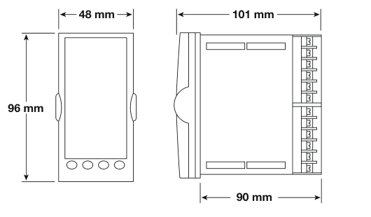
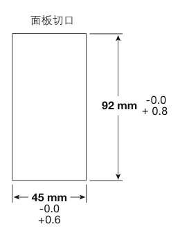
The approximate controller envelope is 48 mm wide, 96 mm high and 101 mm deep. The drawing also identifies a 90 mm rear-body dimension. The panel cutout is 45 mm wide by 92 mm high; the width tolerance is -0.0/+0.6 mm and the height tolerance is -0.0/+0.8 mm. Confirm the drawing and panel clearance during fabrication.
General technical specification
| Item | SX90 data |
|---|---|
| Mounting | Panel mounting, 1/8 DIN |
| Supply | 85-265 Vac; maximum power 9 W |
| Electrical connection | Screw terminals |
| Front protection | IP65 when inserted from the front panel; NEMA 4X |
| Operating environment | 0-55 deg C; 5-85% relative humidity |
| Atmosphere | Not suitable for explosive or corrosive atmospheres |
| Electromagnetic compatibility | EN 61326 |
| Electrical safety | BS EN 61010, installation Category II |
| Mass | 350 g |
| Certification | CE |
Process-variable input and setpoints
| Function | Data |
|---|---|
| Accuracy | Less than +/-0.25% (+/-1 LSD) |
| Resolution | Less than 0.5 microvolt with 1.6 s filter |
| Input filter | Off to 59.9 s |
| RTD | Three-wire Pt100, DIN 43760; indicator current 0.2 mA |
| Linear current | 4-20 mA or 0-20 mA using an external 2.49 ohm shunt resistor |
| Linear voltage | -10 to 80 mV |
| Thermocouples | K, J, N, R, S, B, L, T, C and custom |
| Sampling rate | 4 Hz (250 ms) |
| Cold-junction accuracy | Less than +/-1 deg C at 25 deg C ambient |
| Linear current accuracy | Less than 0.1% of reading |
| Input impedance | 100 Mohm |
| Setpoints | Three local setpoints plus remote setpoint |
| User calibration | Two-point gain and offset |
Remote setpoint and potentiometer input
| Function | Data |
|---|---|
| Remote setpoint input | 0-10 V or 0-20 mA |
| Remote-setpoint accuracy | Less than +/-0.25% (+/-1 LSD) |
| Remote-setpoint resolution | Greater than 14 bits; approximately 0.5 mV for 0-10 V and 2 microvolt for 4-20 mA |
| Remote-setpoint input impedance | Greater than 222 kohm for voltage; greater than 2.49 ohm for current |
| Potentiometer resistance | 100-10 kohm |
| Potentiometer excitation | 0.46-0.54 V |
| Potentiometer resolution | 0.006% of range, greater than 14 bits |
| Potentiometer sampling | 1 Hz |
| Potentiometer detection | Short circuit less than 25 ohm; open circuit greater than 2 Mohm; open wiper greater than 5 Mohm |
Control, relay and output data
| Function | Data |
|---|---|
| Control action | Proportional, integral and derivative control; automatic tuning by one-shot or natural-frequency tuning |
| Proportional band | 1-9999 engineering units; documented sub-ranges include 0.01-300 and 0.1-3000 |
| Integral time | Off to 9999 |
| Derivative time | Off to 9999 |
| IO1 (output 1) | SPST normally open contact |
| OP2 (output 2) | 0-20 mA or 4-20 mA; isolated; 13.5-bit resolution; load less than 550 ohm |
| OP3 (output 3) | 0-20 mA or 4-20 mA; isolated; 13.5-bit resolution; load less than 550 ohm |
| OP4 (output 4) | Changeover relay contact |
| OP5/OP6 (outputs 5 and 6) | Two interlocked SPST normally open contacts for VMD |
| Relay contact rating | Maximum 2 A at 264 Vac resistive load; observe the per-terminal limit when contacts share a common connection |
| Logic inputs | Three logic inputs; contact open greater than 1200 ohm, contact closed less than 300 ohm |
Transmitter supply and communication
| Function | Data |
|---|---|
| Transmitter supply | 18 V +/-15%, maximum 30 mA; 300 Vac double insulation |
| Transmitter load regulation | Less than 1 V at 25 mA |
| Communication hardware | EIA 485 five-wire, EIA 422 compatible |
| Communication protocol | Modbus RTU slave |
| Communication capacity | Up to 64 controllers connected to a management system |
| Communication isolation | 300 Vac double insulation |
Compliance and ordering
The controller is identified as CE certified and the technical sheet cites EMC emissions and immunity requirements to EN 61326-1 and electrical safety requirements to EN 61010-1. Use the applicable local regulations and the supplied installation guide when designing the finished panel.
Order one SX90 process controller. Confirm the input, control/output arrangement, alarm functions, remote setpoint and feedback requirements before releasing the material code.
Safety information
Safe operation depends on correct installation, commissioning, use and maintenance by qualified personnel in accordance with the operating instructions. Follow the applicable plant construction, wiring and safety rules and use suitable tools and protective equipment. Before handling the controller, isolate the supply and any connected hazardous circuits. When removing the instrument from its sleeve, wait at least two minutes after disconnection for capacitors to discharge.
- Install the controller inside an enclosure so that hands and metal tools cannot touch live parts.
- Fit the protective earth connection first and disconnect it last. Do not connect ac supply to low-voltage sensor or low-level input/output terminals.
- Do not exceed 240 Vac continuously between a relay output and logic, dc or sensor connections, or between any connection and ground.
- Do not connect the controller to a three-phase supply with an unearthed star connection.
- Exclude conductive pollution from the enclosure and prevent condensation before installation and wiring.
- Provide an independent overtemperature protection device where a controller fault could overheat the process; the controller alarms do not protect against every failure mode.
Check that the application, material compatibility, electrical limits and maximum and minimum operating conditions are suitable before installation. The guide identifies the instrument for permanent indoor panel installation and states that it is not suitable above 2000 m or in explosive or corrosive atmospheres. If the instrument is stored before use, protect it from humidity and dust between -30 and +75 deg C. Provide safe access, adequate lighting and a controlled permit-to-work arrangement where required. Wiring must comply with the local regulations for the installation, such as BS 7671 or NEC Class 1 methods where applicable.
Unpacking and panel mounting
Ease the latching ears outwards and pull the controller forward to remove it from the sleeve. When refitting it, ensure that the latching ears click into place so that the IP65 sealing is maintained. The supplied parts include the IP65 sealing gasket, panel retaining clips, sleeve, two 2.49 ohm resistors and a snubber.
- Cut the panel to the recommended 45 mm x 92 mm cutout. The width tolerance is -0.00/+0.6 mm and the height tolerance is -0.00/+0.8 mm.
- Fit the IP65 sealing gasket behind the controller front bezel.
- Insert the controller and sleeve through the cutout.
- Spring the panel retaining clips into position and push both clips forward while holding the controller level.
- Remove the protective cover from the display after the instrument is secured.
Allow space behind the panel for the approximately 101 mm overall depth and the terminal blocks. The guide's panel-spacing drawing identifies 38 mm and 10 mm minimum-spacing dimensions in addition to the 45 mm x 92 mm cutout; confirm the actual arrangement during panel design because the drawing is not to scale. The controller is intended for an environment that minimises heat, vibration, shock and electrical interference.
Terminal layout and wiring
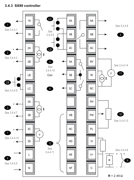
Use only the supplied connectors or genuine replacement connectors. The screw terminals accept 0.5-1.5 mm wire (16-22 AWG), and the rear terminal screws should be tightened to 0.4 N m. Keep input wires separate from power cables. Where shielded cable is used, ground it at one point only. The sensor input is not isolated from the logic outputs and digital inputs.
| Terminals or function | SX90 wiring information |
|---|---|
| 1A / 1B, IO1 (output 1) | Normally open relay output; isolated; use the documented relay contact limit. |
| 2A / 2B, OP2 (output 2) | Analogue output, configurable 0-20 mA or 4-20 mA. |
| 3A / 3B, OP3 (output 3) | SX90 analogue output, configurable 0-20 mA or 4-20 mA. |
| AA / AB / AC, OP4 (output 4) | Changeover relay output; isolated; use the documented relay contact limit. |
| 5A / 5B / 5C, OP5/OP6 (outputs 5 and 6) | Interlocked normally open relay outputs for VMD; shared common connection and per-terminal current limit apply. |
| LB / LC / LD | Volt-free digital inputs for selectable functions such as automatic/manual selection or alarm acknowledgement. Contact open greater than 1200 ohm; contact closed less than 300 ohm. LC and LD are not isolated from each other or from the sensor input. |
| V+, V-, VI | Process-variable input terminals. Use the correct thermocouple compensating cable; match the three RTD wire resistances; fit the supplied 2.49 ohm resistor between V+ and V- for mA input only. |
| RV / RI / RC | Remote setpoint input: 0-10 V between RV and RC, or 4-20 mA between RI and RC. |
| PH / PW / PL | Potentiometer input for valve-position feedback; 100-10 kohm. |
| HB / HC / HD / HE / HF | Five-wire EIA422/EIA485-compatible communication: Rx+, Rx-, common, Tx+ and Tx-. |
| 3C / 3D transmitter supply | The exact SX90 technical sheet specifies 18 V +/-15%, maximum 30 mA. Verify the external transmitter load against this value before connection. |
| L / N | Power input. Use copper conductors and provide external fusing and a nearby, clearly marked disconnecting device. |
Relay loads and sensor connections
When switching an inductive load such as a contactor or solenoid valve, fit the supplied 22 nF / 100 ohm snubber across the normally open relay terminals to reduce interference and extend contact life. A snubber passes current at ac voltage and must not be used where that leakage could hold a high-impedance load on. The guide notes that a suitable EMC filter may also be needed for relay outputs; the cited examples are Schaffner FN321 and FN612, but the correct filter depends on the load.
For a thermocouple, use the correct compensating cable, preferably screened. For a three-wire RTD, keep the three wire resistances equal; line resistance above 22 ohm can cause measurement errors. For a linear mV input use the sensor terminals directly. For a linear mA input, fit the supplied 2.49 ohm resistor between V+ and V- as shown in the wiring diagram. Do not add external components that create excessive or unbalanced line resistance or leakage current without checking their measurement effect.
Switch-on and quick configuration
When an unconfigured controller is first powered, it displays the five-character quick configuration code. The characters are adjusted with the front-panel buttons and then confirmed through the exit screen. An incorrect configuration can damage the process or cause injury, so configuration must be completed by a competent person authorised to commission the installation.
| Character | Function |
|---|---|
| 1 | Input type and range |
| 2 | Control type and associated output type |
| 3 | Function of the input/output 1 alarm relay |
| 4 | Function of the output 4 relay |
| 5 | User-message language |
The home display shows the measured process value and target setpoint, status beacons including OP1 and OP2, and operator buttons. The SX90 display can also show the configured meter value, such as valve position or heat/cool status. The exact display depends on the quick-code configuration.
Quick-code functions for SX90
The five characters must be chosen as a complete configuration. The following options are the SX90 functions in the guide; the available control and output combinations depend on the selected code.
| Character 1 | Input | Range |
|---|---|---|
| P | Pt100 RTD | 99.9 to 300.0 deg C |
| 0 | 4-20 mA | 0 to 1.6 bar |
| 1 | 4-20 mA | 0 to 2.5 bar |
| 2 | 4-20 mA | 0 to 4.0 bar |
| 3 | 4-20 mA | 0 to 6.0 bar |
| 4 | 4-20 mA | 0 to 10 bar |
| 5 | 4-20 mA | 0 to 16 bar |
| 6 | 4-20 mA | 0 to 25 bar |
| 7 | 4-20 mA | 0 to 40 bar |
| 8 | 4-20 mA | -50 to +500 deg C |
| 9 | 4-20 mA | 0 to +100 deg C |
| K | Type K thermocouple | -200 to +1372 deg C |
| Character | SX90 control and output function |
|---|---|
| D | Boundless valve positioning on OP5/OP6; alarm relay on IO1. |
| V | Bounded valve positioning on OP5/OP6; alarm relay on IO1 with analogue feedback. |
| P | Bounded valve positioning on OP5/OP6; alarm relay on IO1 with potentiometer feedback. |
| A | Analogue heat/cool PID output on OP2/OP3; alarm relay on IO1 and alarm relay on OP4. |
| H | Analogue heat-only PID output on OP2; OP2 tracks OP3; alarm relay on IO1 and alarm relay on OP4. |
| Character | Available functions |
|---|---|
| 3, IO1 alarm relay | X unconfigured; full-scale high; full-scale low; deviation high; deviation low; or deviation band. Alarm operation is manually latched by default. |
| 4, OP4 relay | X unconfigured; full-scale high; full-scale low; deviation high; deviation low; or deviation band. Alarm operation is manually latched by default. |
| 5, user-message language | E English, F French, S Spanish, I Italian or G German. |
Commissioning and operation
From the home display, hold the mode buttons together and select Auto, Manual or Off. In Manual mode, use the increase or decrease buttons to adjust output power. Adjust the target temperature or pressure setpoint from the home display and confirm the change when the value is released. During commissioning, use the protected Level 2 parameters to set the working output and setpoint limits, units, ramp rates, alarm setpoints, motor travel time, auto-tune enable, proportional band, integral time and derivative time.
| Level 2 parameter | Documented purpose or range |
|---|---|
| SP.HI / SP.LO | High and low limits for SP1, SP2, SP3 and REM.SP. |
| SP1, SP2, SP3 | Local setpoint adjustments between the configured high and low limits. |
| SP.RRT / SP.FRT | Rising and falling setpoint-rate limits, Off to 3000 units/min. |
| HOLD.B | Setpoint-ramp holdback, Off or 1-9999. |
| A1/2.xx | High, low, deviation-high, deviation-low or deviation-band alarm setpoint. |
| MTR.T | Motor travel time, 0.0-999.9 seconds. |
| A.TUNE | Automatic tuning enable; On starts the process-tuning operation. |
| PB / TI / TD | Proportional band 1-9999 display units; integral time 1-9999 seconds or Off; derivative time Off or 1-9999 seconds. |
| MR | Manual reset, -100.0% to +100.0% where applicable. |
| R2G / D.BAND | Relative cooling gain 0.1-10.0; channel 2 deadband Off or 0.1-100.0% of the cooling proportional band. |
When an alarm is active, the red alarm beacon flashes and a scrolling message identifies the source. An alarm output de-energises by default. Acknowledgement requires the documented button combination, and the default alarm behaviour is manual latching until the alarm condition has cleared. If quick configuration must be re-entered, power down the controller, hold the documented button while powering up and enter the pass code.
Maintenance
The instrument has no user-serviceable parts. Contact the supplier for repair. Clean labels only with isopropyl alcohol; do not use water-based products on the labels. Before removing the controller from its sleeve, isolate the supply and allow the capacitor discharge time specified in the safety information. Any work on the connected process or panel must also follow the site's isolation, permit and electrical-safety procedures.
The guide includes a restricted-substances declaration for the controller and cites SJ/T11363-2006. Retain the official declaration with the project compliance records rather than treating this product page as a substitute for the applicable conformity documentation.