
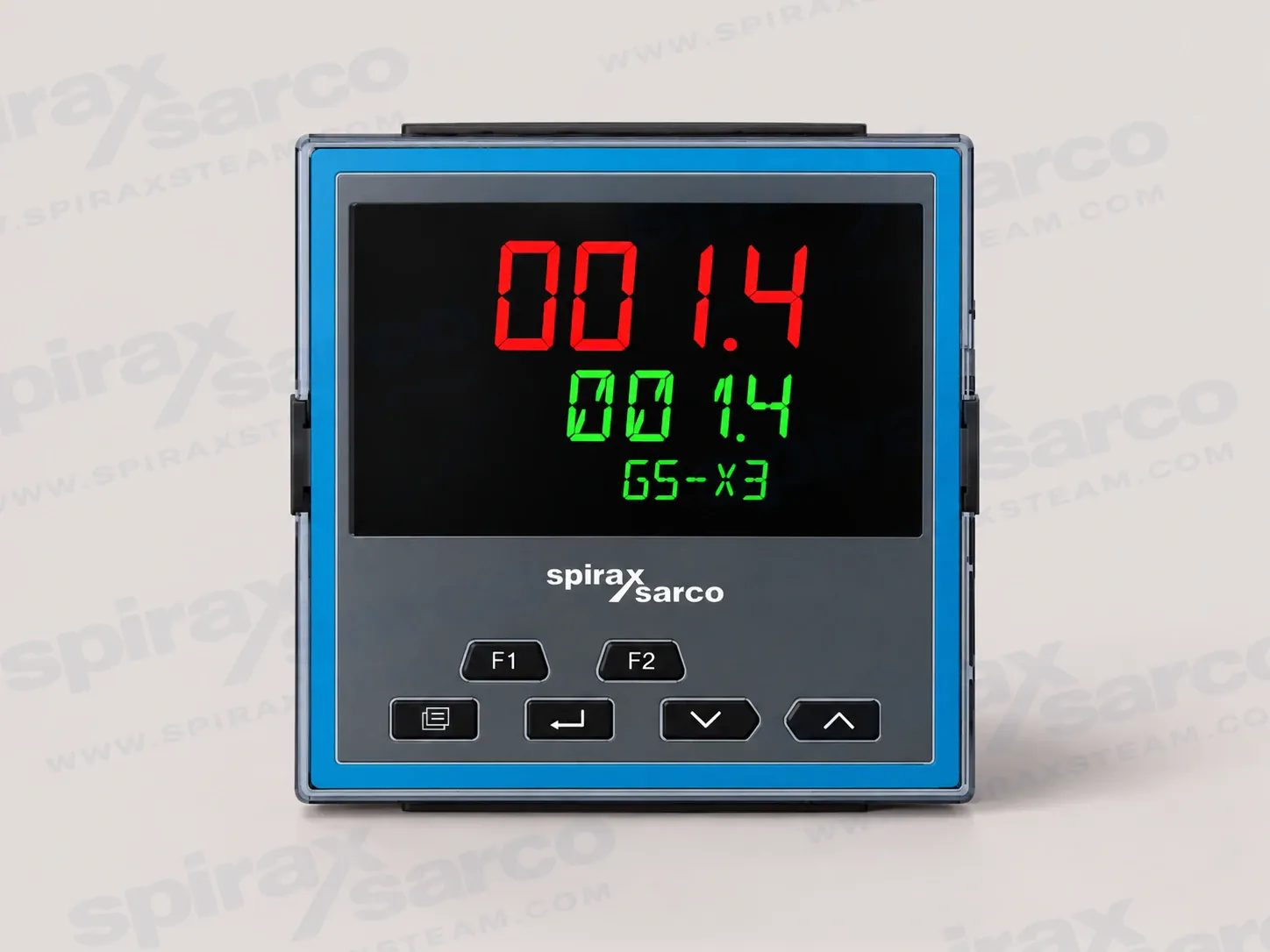
GS-X3
GS-X3 Programmable PID Controller
GS-X3 is a 1/4 DIN panel-mounted programmable single-loop PID controller with one universal process input, an optional second input, configurable I/O, isolated 24 Vdc transmitter power and standard EIA-485 communications for thermal and other process control.
Spirax Sarco GS-X3 programmable PID controller
The Spirax Sarco GS-X3 is a 1/4 DIN panel-mounted programmable single-loop PID controller for thermal and other process control. Its larger panel format provides a clear operator interface while retaining the measurement accuracy, configurable control functions and plant communication options expected from a modern process controller. The instrument is specified as part of an engineered loop: the sensor, controlled process, final control element, alarm strategy and safe response to faults must be assessed together.
A controller does not replace independent protection where the process risk assessment requires it. When the output is used to drive a modulating valve, review the control valve range alongside the selected output type, actuator requirements and fail position. This keeps the controller configuration and the final control element aligned instead of treating an output rating as proof that a complete control loop is suitable.
Programmable control for changing process conditions
Spirax Sarco GS-X3 provides a programmable single-loop control platform. The documented control functions include PID control with enhanced autotuning and a cutback function, on/off control, valve positioning without a slidewire, gain scheduling and feedforward. Cutback is intended to help limit overshoot and oscillation as a loop approaches its setpoint, while autotuning helps establish control parameters for the actual process response. The result still depends on the sensor dynamics, load, actuator and tuning procedure, so these functions should be commissioned against the real installation.
Two PID sets are available as standard, with an optional extension to eight sets. Separate proportional behaviour for heating and cooling can be assigned within the documented PID arrangement. Gain scheduling can select a suitable PID set as operating conditions change, including changes in deviation from setpoint or output level. Feedforward can use the process variable, setpoint or monitored AC supply voltage when the ordered configuration supports the function. These options are useful for processes with changing demand, but they should be enabled only when the control strategy and fallback behaviour have been reviewed.
Setpoint programming is available as an option. The technical information describes configurations including up to 20 profiles of 8 steps, with ramp, dwell, holdback, time-to-target and event behaviour available within the programmer functions. A programmed sequence can provide repeatable thermal processing or another controlled routine, while event outputs can coordinate auxiliary operations. Confirm the required profile capacity, event functions and installed I/O before ordering; a capability listed for the platform does not mean it is present in every instrument.
Function-block wiring can add mathematics, logic, multiplexing, timers, counters, totalisation, recipes, linearisation, zirconia functions and input monitoring to the core loop. These blocks allow signal conditioning, selection logic and interlocks to be represented close to the controller configuration. They do not remove the need for independent hardwired protection where required. During commissioning, test each active path, alarm, manual mode, standby response and communication-loss response before the controller is connected to a live process.
Universal measurement and optional second input
GS-X3 has one universal primary process input, and a second universal input can be ordered for applications requiring an additional measurement. The documented input family includes thermocouples, Pt100 and Pt1000 resistance thermometers, 4-20 mA and 0-20 mA current signals, 10 V, 2 V, 0.8 V, 80 mV and 40 mV voltage ranges, zirconia oxygen probes and pyrometers. The technical sheet specifies an input accuracy of +/-0.1% of reading. Sample timing is 50 ms for process inputs, 62.5 ms for thermocouples and 100 ms for RTD measurements.
Input filtering can be set from off to a 60 second time constant. Standard thermocouple types include K, J, N, R, S, B, L and T, with two downloadable custom curves also documented. Cold-junction calibration and external cold-junction choices are part of the configured measurement arrangement. Before ordering, record the sensor type, signal range, engineering unit, calibration method and sensor-break response. A universal input accepts several signal families, but each installation still needs the correct wiring, compensation method and any specified burden resistor.
The optional secondary input can support a second process value or configured dual-input functions such as switchover, redundancy, average, minimum, maximum or zirconia-related control. Its purpose is determined by the hardware and software configuration. Do not infer a particular control mode from the presence of a second input; confirm the intended measurement, terminal assignment and logic in the current order code and commissioning record.
For the Spirax Sarco GS-X3, input selection is therefore part of the application definition rather than a late wiring detail. The sensor range, input filtering, calibration approach and response to a broken sensor should be agreed with the process owner before the controller is configured.
I/O for actuators, alarms and plant integration
The Spirax Sarco GS-X3 format documents one Form C changeover relay, two contact-closure inputs, a current-transformer input and an isolated 24 Vdc transmitter power supply as standard features for this controller format. Up to three optional I/O modules can be selected from Form A relay, logic I/O, isolated DC analogue output and TRIAC types. Depending on the selected hardware and soft wiring, these interfaces can provide time-proportioned heating or cooling, proportional valve or SCR drive, retransmission, alarm and event outputs, interlocks or contact inputs.
The optional open-collector logic I/O is available with 4 or 8 channels. It uses an external 15 to 35 Vdc supply and has a maximum current-sinking limit of 40 mA. The technical sheet states that this interface can serve alarm, event and interlock functions but cannot be used as a control output. This distinction matters when a wiring design includes both status logic and a real control demand: select a rated relay, TRIAC, logic drive or analogue module for the control function as appropriate.
The current-transformer input is intended for load-monitoring functions such as partial-load, open-circuit or short-circuit detection when the application is configured for it. It accepts the documented 0-50 mA rms signal and uses an internal burden resistor. A load-monitoring indication can help the control strategy respond to a heater fault, but it is not a substitute for correctly rated circuit protection, isolation or a defined safe state.
The isolated 24 Vdc transmitter supply is documented with a maximum 28 mA load. It can simplify a two-wire transmitter arrangement, but the actual loop current, sensor wiring, isolation boundary and configured input must be checked before connection. The controller also provides standard EIA-485 digital communications. An optional Ethernet interface uses a shielded grounded RJ45 connection with 10/100BASE-T auto-sensing. Modbus TCP, BACnet and EtherNet/IP are listed for the Ethernet option; the protocol, role and available features depend on the ordered hardware and software.
Operator visibility and panel integration
The Spirax Sarco GS-X3 uses a high-visibility backlit display with a 5-digit main process value and four decimal places. Its green/red bicolor indication can show red in an alarm condition. A 5-character second line, scrolling text, units, output and alarm indicators, programmer status, communication activity and a configurable bar graph can provide local context without relying on a separate display. Two programmable function keys are available in addition to the navigation controls, and passcode-protected levels help separate routine operation from engineering configuration.
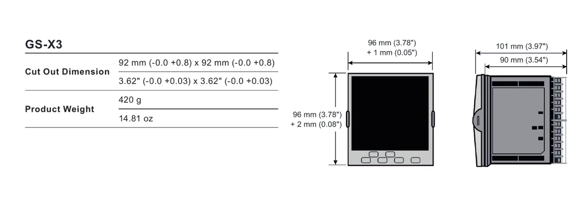
GS-X3 is the 1/4 DIN format with a nominal 96 x 96 mm face. The documented panel cut-out is 92 x 92 mm with -0/+0.8 mm tolerances in both dimensions. The rear depth behind the panel is approximately 90 mm and the product weight is approximately 420 g. The technical drawing also shows the outer front and latching envelope, so the complete drawing should be checked for the selected bezel and surrounding clearance before a panel is fabricated.
The installation location is permanent, indoors and inside an electrical panel or cabinet. The technical sheet specifies operation from 0 to 55 deg C, storage from -20 to +70 deg C and 5% to 90% RH non-condensing. The atmosphere must be non-corrosive and non-explosive. A washdown bezel provides the stated IP66 and UL50E Type 4X-equivalent front protection for indoor use, while the rear is IP10. These enclosure ratings do not make exposed terminals safe or remove the requirement for a suitable cabinet.
Configuration, safety and application limits
The primary sensor input, current-transformer input and digital inputs or outputs are not isolated from one another. If a sensor can be at line potential, the associated terminals, cables and connected devices must be selected and handled for that potential. The controller must be installed, wired, commissioned and maintained by qualified personnel, with power to the product and connected I/O isolated before work begins. The supplied terminal labels and the current installation instructions take precedence over assumptions based on the physical location of a connector.
Configuration mode can place the control strategy into standby and change how outputs behave. A new unconfigured instrument uses Quick Start selections, while an instrument supplied with hardware and software codes can start with a configured operator display. In either case, verify the sensor range, control action, setpoint limits, alarm thresholds, programmed sequences, output action and fallback response. Test normal operation and fault cases such as sensor break, loss of communications, transmitter failure, output failure and loss of power.
For a migration or replacement assessment, compare the existing process variable, I/O allocation, control action, alarm strategy, configured logic and commissioning records with the proposed GS-X3 order code. The SX80 process controller page can serve as a related process-controller reference, but its existence does not establish equivalence with GS-X3. The final specification must follow the process requirements and current configuration documentation.
Spirax Sarco GS-X3 ordering checklist
Specifying a Spirax Sarco GS-X3 is an application and order-code exercise. Confirm the following points before the final instrument configuration is released:
- Define the primary process variable, sensor type, signal range, engineering units, calibration method and sensor-break response.
- Decide whether the optional secondary universal input is required and document its intended measurement or dual-input function.
- Choose the control action, heating or cooling strategy, PID sets, autotune approach, alarms, programmer capacity and function-block options.
- Confirm the Form C relay, optional I/O modules, contact inputs, current-transformer circuit and any open-collector channels against the load and interlock design.
- Confirm the 24 Vdc transmitter load, EIA-485 or Ethernet communication option, protocol role, bezel style and supply voltage from the current order code.
- Check the 92 x 92 mm cut-out, approximately 90 mm rear clearance, environmental conditions, cabinet rating and isolation boundaries before installation.
Installation, wiring, commissioning and maintenance must follow the official instructions and local electrical requirements. A verified configuration and documented response to abnormal conditions are as important as the selected input and output modules.
Product function
GS-X3 is a panel-mounted programmable single-loop PID controller in a 1/4 DIN format for thermal and other process control. The documented functions include PID control with enhanced autotuning and cutback, on/off control, valve positioning without a slidewire, gain scheduling, feedforward, alarms, recipes and optional setpoint programming. The functions available on an installed instrument depend on the ordered hardware and software configuration.
The controller has one universal primary process input and an orderable second universal input. The GS-X3 format includes one Form C changeover relay, two contact-closure logic inputs, a current-transformer input and an isolated transmitter power supply. Up to three optional I/O modules can be selected from Form A relay, logic I/O, isolated DC analogue output and TRIAC types.
Environmental specifications and protection
| Item | GS-X3 documented value |
|---|---|
| Operating temperature | 0 to 55 deg C (32 to 131 deg F) |
| Storage temperature | -20 to +70 deg C (-4 to 158 deg F) |
| Operating/storage humidity | 5% to 90% RH, non-condensing |
| Atmosphere | Non-corrosive and non-explosive |
| Installation environment | Indoor use only, in an electrical panel or cabinet |
| Front protection | Washdown bezel: EN 60529 IP66 and UL50E Type 4X, equivalent to NEMA 4X for indoor use |
| Rear protection | EN 60529 IP10 |
| Electrical safety | EN 61010-1, installation category II, pollution degree 2 |
| EMC | EN 61326-1 industrial immunity; supply emission class depends on the power-supply version |
Dimensions, cut-out and weight
| Dimension or mass | GS-X3 value |
|---|---|
| Panel cut-out | 92 x 92 mm, -0/+0.8 mm width and -0/+0.8 mm height (3.62 x 3.62 inch, -0/+0.03 and -0/+0.03 inch) |
| Nominal front size | Approximately 96 x 96 mm |
| Front drawing allowances | Approximately 96 mm plus 1 mm horizontally and 96 mm plus 2 mm vertically in the technical drawing; verify the selected bezel and latching envelope |
| Depth behind panel | Approximately 90 mm; the drawing shows approximately 101 mm for the full rear/latching envelope |
| Product weight | Approximately 420 g (14.81 oz) |
Universal process inputs
| Characteristic | GS-X3 specification |
|---|---|
| Input arrangement | One universal primary input; one additional universal input available as an option |
| Input types | Thermocouples, Pt100/Pt1000 RTD, 4-20 mA, 0-20 mA, 10 V, 2 V, 0.8 V, 80 mV, 40 mV, zirconia oxygen probe and pyrometers |
| Input accuracy | +/-0.1% of reading |
| Process input sample time | 50 ms (20 Hz) |
| Thermocouple sample time | 62.5 ms (16 Hz) |
| RTD sample time | 100 ms (10 Hz) |
| Input filter | Off to 60 s filter time constant |
| Thermocouple types | K, J, N, R, S, B, L and T as standard, plus two downloadable custom curves |
| Nominal linear ranges | 40 mV, 80 mV, 0.8 V, 2 V, 10 V and current input up to the documented +/-32 mA range; RTD resistance range up to 400 or 4000 ohm as applicable |
| Sensor break | AC sensor-break detection; worst-case detection within 3 s |
| User calibration | Two-point input offset/gradient adjustment and transmitter-output scaling |
Optional input and I/O arrangements
| Interface | Documented GS-X3 arrangement |
|---|---|
| Secondary universal input | Orderable second process input for thermocouple, RTD or linear measurement; the configured application determines its function |
| Standard output | One OP3 Form C changeover relay, isolated 300 Vac CAT II; contact rating 2 A at 230 Vac +15% resistive |
| Optional I/O modules | Up to three freely selectable modules: Form A relay, logic I/O, isolated DC analogue output or TRIAC output |
| Contact-closure inputs | Two digital contact inputs; open above 400 ohm and closed below 100 ohm |
| Current-transformer input | 0-50 mA rms, 48-62 Hz; internal 10 ohm burden resistor; used for partial-load and load-fault functions |
| Open-collector logic I/O | Optional 4 or 8 channels; external 15-35 Vdc supply; maximum current sinking 40 mA; not a control output |
| Transmitter power supply | Isolated 24 Vdc supply; 2-28 mA load in the technical sheet and 28 mA maximum in the installation guide |
Power and communications
| Item | GS-X3 specification |
|---|---|
| High-voltage AC supply | 100-230 Vac +/-15%, 48-62 Hz |
| Low-voltage AC supply | 24 Vac +10%/-15%, 48-62 Hz |
| Low-voltage DC supply | 24 Vdc +20%/-15%, maximum 5% ripple voltage; polarity is not important |
| Power rating | Maximum 9 W |
| Overvoltage category | CAT II |
| Standard communications | EIA-485 (RS-485) digital communications |
| Ethernet option | Shielded grounded RJ45, 10/100BASE-T auto-sensing, fixed IP address or DHCP, with Bonjour auto-discovery |
| Ethernet protocols | Modbus TCP, BACnet and EtherNet/IP, subject to the selected option and software configuration |
| Serial protocol details | Where applicable, serial communication uses the documented EIA-485 arrangement and configured protocol parameters; verify the current order code before wiring |
Display and operator interface
| Item | GS-X3 documented value |
|---|---|
| Display | High-visibility backlit LCD with a washdown membrane bezel or a sculpted bezel with tactile keys |
| Main process variable | 5 digits with four decimal places; green/red bicolor indication with red in alarm |
| Second line | 5-character 16-segment text or numeric display |
| Scrolling line | 16-segment scrolling text or numeric display |
| Displayed status | Process value, units, setpoint, output status, alarm indication, programmer status, communications activity and configurable bar graph |
| Function keys | Two programmable function keys, subject to configuration |
| Protection | Passcode level protection with configurable lockout period |
Control, approvals and ordering notes
- Enhanced autotuning includes a cutback function intended to reduce overshoot and oscillation.
- Two PID sets are documented as standard, with an optional extension to eight PID sets.
- Setpoint programmer options include up to 20 profiles of 8 steps; confirm the selected application and option code.
- When the necessary field calibration is completed, the source states that supplied controllers can meet the accuracy requirements described for AMS2750F and CQI-9 applications. This is not a substitute for the applicable quality-system validation.
- Order the controller against the current hardware and software code. Confirm the sensor, second input, output modules, transmitter load, communications, bezel, supply, labels and application before purchase.
- The controller contains no user-serviceable parts. The source lists a USB backup lead, iTools configuration software, snubbers, resistors and current transformers as accessories.
Installation and Maintenance Guide
- Safety information
- Controller introduction
- Panel installation and removal
- Terminal wiring and isolation
- Start-up and configuration
- Operator interface and commissioning
- Cybersecurity, maintenance and disposal
These instructions apply the verified GS-X3 installation, wiring and operating boundaries from IM-P794-03 to the single-model product page.
1. Safety information
Electrical equipment must be installed, operated and maintained by qualified personnel. Before installation, removal, wiring, maintenance or inspection, turn off all power to the controller and to connected I/O circuits such as alarms and control outputs.
Intended use and system responsibility
Use the controller only within the specified technical data, instructions and applicable regulations. Perform a risk assessment for the planned application and implement the required safety measures. The controller is a component of a larger machine or process; the designer and commissioning person remain responsible for the safety of the complete system.
Electrical and fire hazards
Install the unit in an enclosure or cabinet that provides fire containment and restricts access to hazards. Do not exceed the ratings. Wire and fuse power-line and output circuits according to local and national requirements. Use the correct supply version shown on the controller label and use isolating PELV or SELV supplies for low-voltage equipment.
Live sensor boundary
The primary sensor input is not isolated from the current-transformer input or digital inputs and outputs. If the sensor is at a hazardous potential, associated terminals can be at the same potential. Protect service personnel and use cables, connectors and switches rated for the applicable voltage and category.
Control and configuration hazards
Do not use the controller as the sole protection in a critical application where people or equipment rely on the control circuit. Do not configure it while connected to a live process: entering Configuration mode pauses outputs. Use suitable interlocks and test all normal and fault conditions before approval for service.
2. Panel installation
GS-X3 is intended for permanent indoor installation in an electrical panel. Choose a low-vibration location with an ambient operating temperature of 0 to 55 deg C and use the conservative technical-sheet humidity range of 5% to 90% RH non-condensing. The controller can be mounted in a panel up to 15 mm thick. A minimum 2 mm mild-steel panel and a non-textured mounting surface are recommended to maintain effective sealing and the stated front protection.
- Prepare a 92 x 92 mm cut-out with -0/+0.8 mm width and -0/+0.8 mm height tolerances. When multiple controllers are fitted, allow at least 10 mm spacing.
- Switch off all power and carefully remove the panel retaining clips from the sleeve.
- Check that the gasket is behind the front bezel, is not twisted and is suitable for the panel surface.
- Insert the sleeve and controller through the cut-out, then push both retaining clips forward until the instrument is secure and the panel seal is maintained.
- Remove the display protective film after installation. If the sleeve must be removed, first isolate all power and remove any Ethernet cable from the rear of the controller.
Polarising features help prevent an inverted installation, an incompatible power-supply unit being inserted into a sleeve and an instrument being inserted into a sleeve with a non-compatible terminal assignment. Do not rely on the polarising features in place of checking the order code and terminal label.
3. GS-X3 terminal layout and options
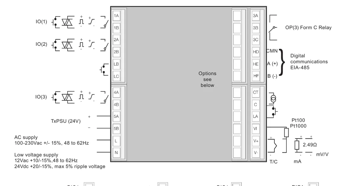
The GS-X3 terminal arrangement provides the primary sensor input, optional secondary sensor input, OP3 Form C changeover relay, standard 24 V transmitter supply, current-transformer and digital-input connections, power terminals and option positions. I/O1, I/O2 and the available option positions can be ordered as relay, TRIAC, logic or analogue functions according to the installed modules, while OP3 remains the standard changeover relay. Do not connect a module or signal to a terminal solely because the location appears available; verify the supplied hardware and wiring label.
4. Wiring and isolation
Secure cables and wiring harnesses with appropriate strain relief and prevent conductive material from entering the case. Use only the identified terminals and the originally supplied connectors. Keep sensor and low-voltage DC wiring away from high-current power wiring. Where separation is impractical, use suitable shielded cable with the shield grounded as specified by the installation design.
| Wiring item | Installation requirement |
|---|---|
| Terminal wire size | 0.5-1.5 mm2; maximum two wires per terminal, identical in type and cross-sectional size |
| Stripping | Strip at least 6 mm of insulation and do not leave more than 2 mm of exposed conductor |
| Terminal screws | Tighten to the specified torque of 0.5 Nm and verify the conductor is secure |
| Power supply | Match the supply to the rating on the controller label; do not connect a low-voltage version directly to line voltage |
| Transmitter supply | The internal 24 Vdc supply is isolated and limited to the documented 28 mA maximum; verify transmitter wiring and input configuration before connection |
| Current transformer | Provide voltage limiting across the CT terminals to reduce hazardous voltage when the controller is unplugged if a current transformer is used |
| Inductive load | Use the specified snubber/protection arrangement where required; confirm that leakage current will not hold a high-impedance load on |
Isolation diagrams in the source identify 300 Vac double or basic isolation boundaries. The primary sensor, CT, digital-input and digital-output relationships require a specific safety review because these circuits are not isolated from one another. Do not infer isolation from a terminal position or from the use of a low-voltage sensor alone.
5. Start-up and configuration
At power-up the controller performs a display diagnostic and checks the fitted hardware. A hardware mismatch or keyboard-check failure can place the instrument in standby. A new unconfigured controller enters Quick Start mode, where two sets of five characters are used to select the application, sensor type, range and available digital functions. A controller supplied with a hardware and software code can start directly in its configured operator display.
- Confirm the supply, primary and secondary sensor wiring, output wiring, enclosure, interlocks and isolation before energising the controller.
- For a new unconfigured unit, enter the Quick Start selections for the actual application. Do not select a function whose required hardware is not fitted.
- For a configured unit, check the application, input ranges, control action, setpoint limits, alarm thresholds and output behaviour.
- Use Configuration level or the iTools configuration package for functions not exposed by the quick codes. Save a verified configuration backup before making major changes.
- Test sensor-break, alarm, manual, standby, communication-loss, transmitter and output-fault behaviour under controlled commissioning conditions.
Changing configuration or flash-memory settings can place the controller in Configuration mode and stop process control. Configuration changes must therefore be made with the process in a safe state and must be approved before returning the system to service.
6. Operator interface and commissioning
GS-X3 uses Page, Scroll, Lower and Raise navigation controls together with two programmable function keys. Page selects displays or list headers, Scroll selects parameters, and Lower/Raise adjust values within the permitted limits. The function keys can be assigned to configured actions such as Auto/Manual selection. Holding Page for more than three seconds selects the Goto function, and Page plus Scroll returns to the Home display.
Commissioning should confirm the process-variable indication, engineering units, active setpoint, output indication, alarm indication, manual/automatic behaviour, programmed sequences, bar graph and communications status. Check the response after a process disturbance and verify that the selected control output cannot drive an actuator beyond the safe operating boundary. Where the controller drives a valve, confirm that the output action and actuator fail position agree with the process risk assessment.
7. Network and cybersecurity
When a communications option is used, protect the controller as part of the industrial control network. The installation guidance recommends that controllers and associated devices are placed on a firewalled network segment separated from the public Internet, rather than being directly exposed. Disable unused communication features, change default access credentials where applicable, restrict configuration access and document the permitted master devices and network paths.
Validate the complete system after a power cycle, communications interruption or configuration recovery. A network message can continue to influence an output if the output is configured for communications control, so the loss-of-communications response and local fallback must be tested explicitly.
8. Maintenance, cleaning and disposal
The controller contains no user-serviceable parts. Isolate all power and I/O before inspection or removal, observe electrostatic-discharge precautions and do not disassemble, repair or modify the equipment. Contact the supplier for repair or replacement. Use only the specified accessories and genuine replacement items.
A mild soap solution may be used on exterior surfaces; isopropyl alcohol may be used for labels as described by the source instructions. Prevent liquid or conductive material from entering the case. If stored before use, keep the instrument within the specified storage temperature and humidity conditions. Dispose of the equipment in accordance with the applicable WEEE and local electronic-equipment requirements.