
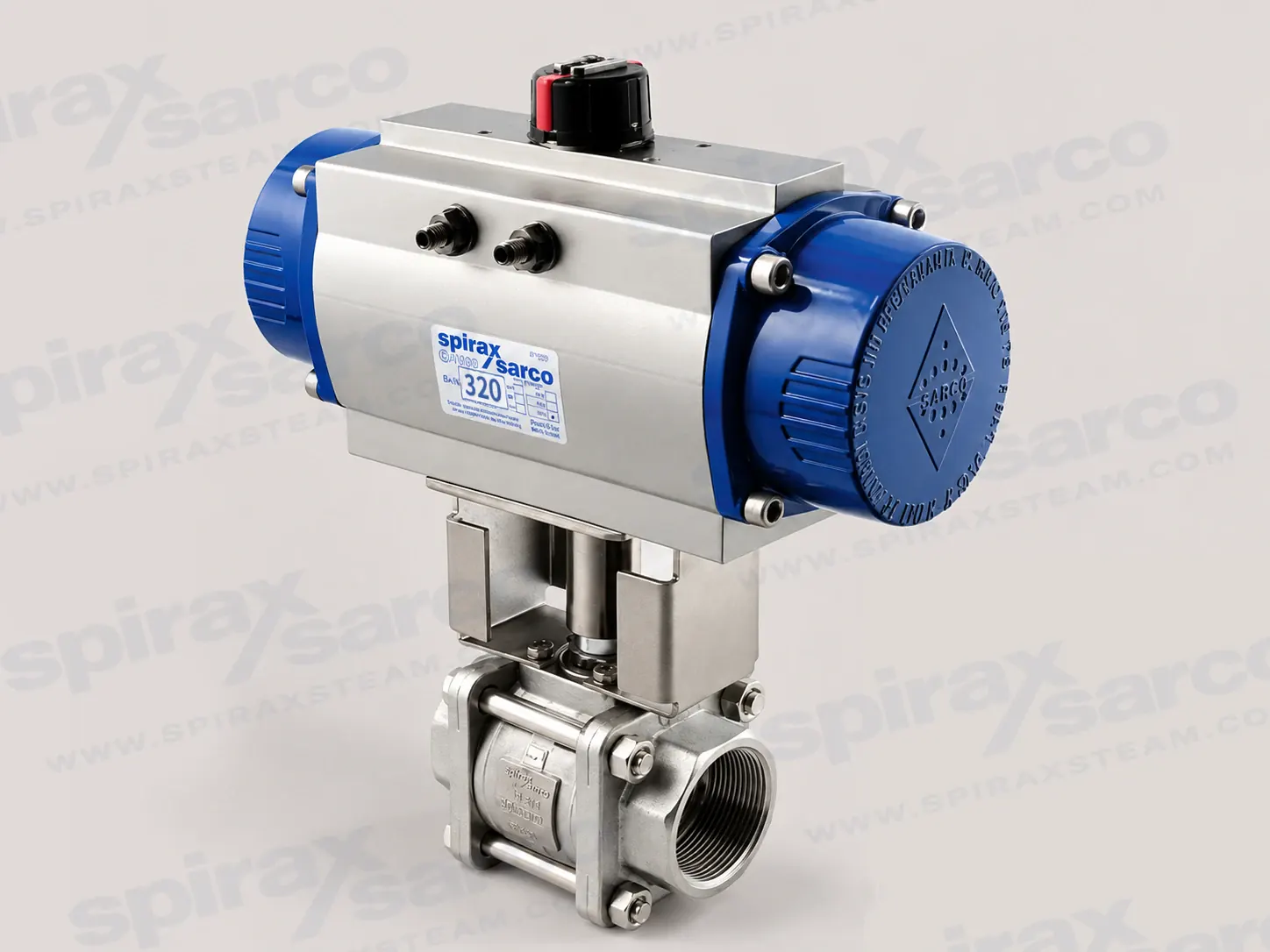
BVA300 pneumatic actuator for automated ball valves
Spirax Sarco BVA300 is a pneumatic rotary actuator range for automating compatible ball valves in industrial fluid systems. It converts the linear movement of pneumatic pistons into a quarter-turn output through a rack-and-pinion mechanism. This gives a compact route from an air signal to the open or closed position of a valve, while the actuator's bi-directional travel stops allow the final rotation to be adjusted around the nominal 90 degree operating angle.
The range is available as double-acting and spring-return configurations. Double-acting units use air to drive the actuator in both directions. Spring-return units use pre-compressed springs in the end caps so that the selected fail position can be achieved when the air supply is removed, subject to the valve, linkage and spring combination being correctly selected. The official range covers BVA310D through BVA365D and BVA310S through BVA365S. A suffix such as /4, /6, /8, /10, /12 or /14 identifies a documented spring combination where applicable; the exact combination must be taken from the selection tables for the valve duty.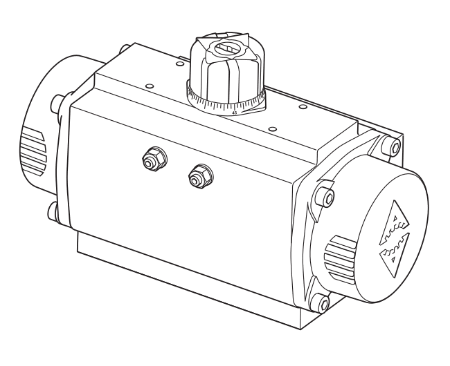
How the BVA300 operates
In a rack-and-pinion actuator, air pressure moves the internal pistons along the body and the toothed racks turn the central pinion. The result is rotary motion suitable for a quarter-turn ball valve. The BVA300 travel stops are bi-directional. The installation guide describes adjustment between 85 and 95 degrees, with one third of a locking-nut turn corresponding to approximately one degree of stroke. The manufacturer's setting must not be adjusted by more than 2.5 degrees on either side because internal parts could be damaged.
Spirax Sarco BVA300 is therefore an actuator family rather than one fixed torque or one universal valve assembly. The correct size depends on the connected valve, operating pressure, action, spring combination and linkage. The technical information uses 3, 4, 5 and 6 bar g as the standard selection-table air pressures. Those table values should be treated as selection conditions, not as permission to combine an actuator and valve without checking the complete assembly.
Construction and operating conditions
The standard actuator body is hard-anodized aluminium. The pinion is nickel-plated carbon steel, the end caps are epoxy-coated aluminium, the external bolts are stainless steel and the indicator cap and coloured indicator are polyamide. This material set supports a relatively light actuator construction while keeping the moving drive elements and visible position indication suitable for the documented industrial service. The installation guide identifies the standard actuator material as aluminium and gives a PN8 pressure designation alongside the 8 bar g maximum pressure.
The documented standard operating temperature is -30 °C to 100 °C. The technical sheet notes that other operating temperature ranges may be available on request, but that possibility must be confirmed for the actual configuration. The maximum pressure is 8 bar g and the minimum pressure is 3 bar g. The specified operating media are clean and dry compressed air, non-corrosive gas, and light hydraulic oil that is compatible with the actuator's O-rings. Wet or contaminated air can reduce service life, so air preparation belongs in the actuator selection and installation review.
The actuator uses a NAMUR G 1/4 DIN air inlet. The installation guide records NAMUR VDI/VDE 3845 for direct solenoid and accessory mounting and EN ISO 5211 for valve connections. These interfaces help coordinate the actuator, control accessory and valve, but they do not remove the need to verify the specific linkage dimensions. BVL_X linkage kits are used for the documented extended-stem arrangement; the technical sheet specifically excludes the extended-stem arrangement for M10MVi and M10MSi ball-valve models.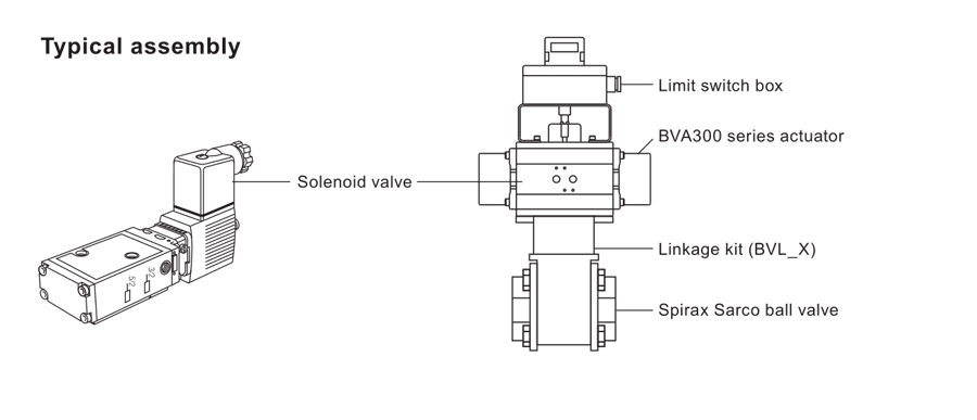
Control and feedback options
A limit switch box can provide position feedback, with the detailed accessory information referenced by TI-P372-26. NAMUR solenoid valves are available to drive the actuator with compressed air or non-corrosive gas. The technical sheet lists a 3/2 NAMUR arrangement for BVAS single-acting configurations and a 5/2 NAMUR arrangement for BVAD double-acting configurations. Documented coil choices are 220 Vac, 110 Vac and 24 Vac/dc. Explosion-proof solenoid valves are noted as available on request, but the solenoid and any other electrical or mechanical accessory must carry and satisfy its own conformity requirements for the final assembly.
These options allow the BVA300 to sit within a simple open/close package with feedback, local pneumatic control or both. They should be specified as accessories for a confirmed actuator and valve combination, rather than treated as universal parts of every BVA300 order.
Where the BVA300 fits
A BVA300 assembly is appropriate where a compatible ball valve needs pneumatic quarter-turn automation. Typical reviews include process isolation, utility services, steam-system auxiliary services and other industrial duties in which a remotely controlled or interlocked valve position is required. The actuator can be paired with a solenoid valve for pneumatic switching and with a limit switch box for position feedback. The actual medium, valve materials, valve pressure class, temperature, cycle frequency and hazardous-area requirements remain properties of the complete valve and accessory assembly.
Because the actuator is selected against valve torque and air pressure, a BVA300 model should not be chosen from the series name alone. Confirm the ball-valve family and nominal size, whether the action is double-acting or spring return, the required spring combination, available air pressure, linkage kit and any feedback or solenoid requirement. The technical information contains separate selection tables for several three-piece, two-piece and one-piece valve families. The named valve models in those tables are compatibility references and do not change this page's BVA300 product scope.
Installation and maintenance checks
Install the actuator where it remains accessible for inspection and maintenance. The actuator and valve must be correctly aligned so the coupling does not introduce external stress. The installation guide recommends proportional tightening of coupling bolts and a final operational check after installation. The actuator is lubricated during assembly and normally does not require additional lubrication. Recommended air quality is maximum 5 mg/m3 oil content, minimum 1 mg/m3 oil content, dry air to prevent freezing and a maximum dust-particle size of 40 microns. For tubing, 6 mm outside diameter is recommended for BVA310 to BVA320. For BVA325 to BVA365, use 6 mm outside diameter for runs up to 1.5 m and 10 mm outside diameter for longer runs.
Preventive maintenance includes operating the actuator at least once every six months, or sooner where the service requires it, and checking for leakage and wear. Before disassembly, isolate and test the air and electrical supplies, disconnect accessories and remove the actuator from the valve or coupling as instructed. The end caps contain springs under load, and a seized partly open valve assembly can retain significant spring energy. The actuator must be vented and the manufacturer's maintenance instructions followed by competent personnel.
What to confirm before ordering
- Connected ball-valve family, nominal size and the compatible BVL_X linkage kit.
- Double-acting or spring-return action, including the spring combination and required fail position.
- Available clean, dry air pressure within the 3 to 8 bar g documented range.
- Operating medium, temperature, valve materials and any chemical compatibility requirement.
- NAMUR solenoid arrangement, coil voltage, position feedback and hazardous-area certification where required.
- Correct alignment, access, tubing length and maintenance isolation provisions at the installation.
Use the full technical and installation information below to check the selected configuration. The phrase Spirax Sarco BVA300 identifies this actuator family; the final order should identify the complete actuator, spring, linkage and accessory configuration shown by the relevant selection table. For product selection, the natural description is a BVA300 pneumatic actuator, but the pressure, valve torque and installation conditions must be confirmed together.
Scope of this web document: the BVA300 actuator range is the target product. Ball-valve model names in the selection tables are retained only as compatibility and selection context; they are not additional products on this page.
Description
The BVA300 series are pneumatic rotary actuators which automate Spirax Sarco ball valves in a wide range of industrial applications. BVA300 actuators are provided with bi-directional travel stops that allow a rotation of 90°±5°. Linkage is made with BVL_X kits with extended stem. The extended-stem arrangement is not available for M10MVi and M10MSi models.
BVA300 pneumatic actuator range
Double-acting selections are BVA310D, BVA315D, BVA320D, BVA325D, BVA330D, BVA335D, BVA340D, BVA345D, BVA350D, BVA355D, BVA357D, BVA360D and BVA365D. Spring-return selections are BVA310S, BVA315S, BVA320S, BVA325S, BVA330S, BVA335S, BVA340S, BVA345S, BVA350S, BVA355S, BVA357S, BVA360S and BVA365S.
Spring-return combinations depend on available air pressure. BVA310S is documented with /4, /6, /8, /10, /12 and /14 combinations; BVA315S through BVA365S are documented with /8, /10, /12 and /14 combinations. See IM-P372-24 for the spring-combination details and safe handling requirements.
Technical data
| Item | BVA300 data |
|---|---|
| Maximum pressure | 8 bar g |
| Minimum pressure | 3 bar g |
| Standard operating temperature | -30 °C to 100 °C (-22 °F to 212 °F) |
| Operating media | Compressed air (clean and dry); non-corrosive gas; light hydraulic oil compatible with O-rings |
| Rotation | 90°±5°, anticlockwise with port A pressurised |
| Air pressure for standard selection tables | 3, 4, 5 and 6 bar g (44, 58, 73 and 87 psi g) |
Other operating temperature ranges are available on request and must be confirmed for the selected actuator.
Optional extras
| Accessory | Documented arrangement |
|---|---|
| Limit switch box | Available; see TI-P372-26 for further details. |
| Solenoid valve | NAMUR electrical valves with encapsulation rating to IP65 for compressed air or non-corrosive gas. Explosion-proof solenoid valves are available on request. |
| 3/2 NAMUR for BVAS | 220 Vac, 110 Vac or 24 Vac/dc coil voltage |
| 5/2 NAMUR for BVAD | 220 Vac, 110 Vac or 24 Vac/dc coil voltage |
Materials
| Part number | Part | Material |
|---|---|---|
| 1 | Body | Aluminium hard anodized |
| 3 | Pinion | Nickel plated carbon steel |
| 4 | End caps | Aluminium epoxy coated |
| 20 | Bolt | Stainless steel |
| 21 | Indicator cap | Polyamide |
| 22 | Coloured indicator | Polyamide |
Pinion details are shown in the spare-parts drawing in the source document.
BVL_X linkage kit components and materials
| Component | Material |
|---|---|
| Frame | Stainless steel AISI 304, carbon steel CF8M and stainless steel WCB (only for M10MVi and M10MSi) |
| Stem adapter | As specified for the compatible valve and linkage selection |
| Frame-to-actuator screws | Stainless steel |
| Washers | Stainless steel |
| Frame-to-valve screws | Stainless steel |
| Stem nut | Stainless steel |
M10M linkage selection note
For the M10M automation kit, the blank bracket option is the short 40 mm bracket for applications below 100 °C (212 °F). The X option is a tall bracket of about 90 mm for higher-temperature applications. The bracket material options are stainless steel (blank) and carbon steel (C); confirm the selected valve and temperature conditions before ordering.
Dimensions and weights
Approximate dimensions are in millimetres (inches) and weights are in kilograms (pounds). A is the double-acting dimension and A1 is the single-acting dimension. The air inlet connection is NAMUR G 1/4 DIN.
| Type | A1 | A | B | C | D | E | Single weight | Double weight |
|---|---|---|---|---|---|---|---|---|
| BVA310 | 163 (6.4) | 145 (5.7) | 96 (3.8) | 76 (3.0) | 48 (1.9) | 34 (1.3) | 1.6 (4) | 1.4 (3) |
| BVA315 | 195 (7.7) | 158 (6.2) | 115 (4.5) | 91 (3.6) | 56 (2.2) | 45 (1.8) | 2.3 (5) | 2.1 (5) |
| BVA320 | 217 (8.5) | 177 (7.0) | 137 (5.4) | 111 (4.4) | 66 (2.6) | 55 (2.2) | 3.7 (8) | 3.0 (7) |
| BVA325 | 258 (10.2) | 196 (7.7) | 147 (5.8) | 122 (4.8) | 71 (2.8) | 60 (2.4) | 4.8 (11) | 3.8 (8) |
| BVA330 | 299 (11.8) | 225 (8.9) | 165 (6.5) | 136 (5.4) | 78 (3.1) | 70 (2.8) | 7.3 (16) | 5.6 (12) |
| BVA335 | 349 (13.7) | 273 (10.7) | 182 (7.2) | 153 (6.0) | 86 (3.4) | 80 (3.1) | 10.8 (24) | 8.5 (19) |
| BVA340 | 397 (15.6) | 304 (12.0) | 199 (7.8) | 173 (6.8) | 96 (3.8) | 85 (3.3) | 15.4 (34) | 11.2 (25) |
| BVA345 | 473 (18.6) | 372 (14.6) | 221 (8.7) | 192 (7.6) | 106 (4.2) | 98 (3.9) | 22.2 (49) | 16.9 (37) |
| BVA350 | 560 (22.0) | 439 (17.3) | 249 (9.8) | 213 (8.4) | 116 (4.6) | 114 (4.5) | 34.3 (76) | 25.8 (57) |
| BVA355 | 601 (23.7) | 461 (18.1) | 280 (11.0) | 243 (9.6) | 131 (5.2) | 130 (5.1) | 46.0 (101) | 32.5 (72) |
| BVA357 | 698 (27.5) | 504 (19.8) | 313 (12.3) | 276 (10.9) | 148 (5.8) | 147 (5.8) | 66.0 (146) | 49.1 (110) |
| BVA360 | 738 (29.1) | 518 (20.4) | 383 (15.1) | 356 (14.0) | 178 (7.0) | 177 (7.0) | 99.9 (220) | 69.6 (153) |
| BVA365 | 940 (37.0) | 630 (24.8) | 434 (17.1) | 415 (16.3) | 213 (8.4) | 201 (7.9) | 183 (403) | 129.4 (285) |
How to order
Refer to the selection tables before placing an order. The source example is one Spirax Sarco BVA320S/8 actuator, one 3/2 NAMUR solenoid at 24 Vac, one 303X linkage kit and one LSB72 limit switch box. Actuated ball valves may be supplied completely assembled to suit the application. Confirm the actuator, valve, linkage, spring combination, solenoid and feedback configuration together.
Selection tables
Pages 5 to 15 contain the information needed to select the correct BVA300 actuator and BVL linkage for the relevant Spirax Sarco ball-valve family. The valve model names below are compatibility context. For valves not appearing in these tables, contact Spirax Sarco for advice.
Page 5: M10Vi, M10Si, M10Ti and M10ECFi4 ball valves
| Operating pressure (bar g) | Valve size / duty | Double-acting BVA | Double-acting BVL | Single-acting BVA | Single-acting BVL |
|---|---|---|---|---|---|
| 3 | ¼" RB - " RB | 310D | 300X | 310S/4 | 300X |
| 3 | ½" RB - " FB | 310D | 300X | 310S/4 | 300X |
| 3 | ¾" RB - ½" FB | 310D | 300X | 315S/8 | 300X |
| 3 | 1" RB - ¾" FB | 315D | 302X | 320S/8 | 303X |
| 3 | 1¼" RB - 1" FB | 320D | 311X | 325S/8 | 311X |
| 3 | 1½" RB - 1¼" FB | 330D | 305X | 340S/8 | 316X |
| 3 | 2" RB - 1½" FB | 330D | 306X | 340S/8 | 307X |
| 3 | 2½" RB - 2" FB | 335D | 309X | 340S/8 | 309X |
| 4 | ¼" RB - " RB | 310D | 300X | 310S/6 | 300X |
| 4 | ½" RB - " FB | 310D | 300X | 310S/6 | 300X |
| 4 | ¾" RB - ½" FB | 310D | 300X | 315S/10 | 300X |
| 4 | 1" RB - ¾" FB | 315D | 302X | 320S/10 | 303X |
| 4 | 1¼" RB - 1" FB | 315D | 310X | 320S/10 | 311X |
| 4 | 1½" RB - 1¼" FB | 325D | 305X | 335S/10 | 316X |
| 4 | 2" RB - 1½" FB | 325D | 306X | 335S/10 | 307X |
| 4 | 2½" RB - 2" FB | 330D | 308X | 340S/10 | 309X |
| 5 | ¼" RB - " RB | 310D | 300X | 310S/6 | 300X |
| 5 | ½" RB - " FB | 310D | 300X | 310S/6 | 300X |
| 5 | ¾" RB - ½" FB | 310D | 300X | 310S/6 | 300X |
| 5 | 1" RB - ¾" FB | 315D | 302X | 320S/12 | 303X |
| 5 | 1¼" RB - 1" FB | 315D | 310X | 320S/12 | 311X |
| 5 | 1½" RB - 1¼" FB | 320D | 305X | 330S/12 | 305X |
| 5 | 2" RB - 1½" FB | 325D | 306X | 335S/12 | 307X |
| 5 | 2½" RB - 2" FB | 325D | 308X | 335S/12 | 309X |
| 6 | ¼" RB - " RB | 310D | 300X | 310S/8 | 300X |
| 6 | ½" RB - " FB | 310D | 300X | 310S/8 | 300X |
| 6 | ¾" RB - ½" FB | 310D | 300X | 310S/8 | 300X |
| 6 | 1" RB - ¾" FB | 310D | 302X | 315S/14 | 302X |
| 6 | 1¼" RB - 1" FB | 315D | 310X | 320S/14 | 311X |
| 6 | 1½" RB - 1¼" FB | 320D | 305X | 330S/14 | 305X |
| 6 | 2" RB - 1½" FB | 320D | 306X | 330S/14 | 306X |
| 6 | 2½" RB - 2" FB | 325D | 308X | 335S/14 | 309X |
Page 5: M10Hi and M10HTi ball valves
| Operating pressure (bar g) | Valve size / duty | Double-acting BVA | Double-acting BVL | Single-acting BVA | Single-acting BVL |
|---|---|---|---|---|---|
| 3 | ¼" RB - " RB | 315D | 490X | 320S/8 | 491X |
| 3 | ½" RB - " FB | 315D | 490X | 320S/8 | 491X |
| 3 | ¾" RB - ½" FB | 315D | 490X | 325S/8 | 491X |
| 3 | 1" RB - ¾" FB | 320D | 493X | 330S/8 | 493X |
| 3 | 1¼" RB - 1" FB | 325D | 494X | 340S/8 | 495X |
| 3 | 1½" RB - 1¼" FB | 330D | 496X | 340S/8 | 497X |
| 3 | 2" RB - 1½" FB | 330D | 498X | 340S/8 | 499X |
| 3 | 2½" RB - 2" FB | 335D | 502X | 345S/8 | 503X |
| 4 | ¼" RB - " RB | 310D | 490X | 320S/10 | 491X |
| 4 | ½" RB - " FB | 310D | 490X | 320S/10 | 491X |
| 4 | ¾" RB - ½" FB | 315D | 490X | 320S/10 | 491X |
| 4 | 1" RB - ¾" FB | 320D | 493X | 325S/10 | 493X |
| 4 | 1¼" RB - 1" FB | 325D | 494X | 335S/10 | 495X |
| 4 | 1½" RB - 1¼" FB | 325D | 496X | 335S/10 | 497X |
| 4 | 2" RB - 1½" FB | 330D | 498X | 340S/10 | 499X |
| 4 | 2½" RB - 2" FB | 335D | 502X | 340S/10 | 502X |
| 5 | ¼" RB - " RB | 310D | 490X | 315S/12 | 490X |
| 5 | ½" RB - " FB | 310D | 490X | 315S/12 | 490X |
| 5 | ¾" RB - ½" FB | 315D | 490X | 320S/12 | 491X |
| 5 | 1" RB - ¾" FB | 315D | 492X | 325S/12 | 493X |
| 5 | 1¼" RB - 1" FB | 320D | 494X | 330S/12 | 494X |
| 5 | 1½" RB - 1¼" FB | 325D | 496X | 335S/12 | 497X |
| 5 | 2" RB - 1½" FB | 325D | 498X | 335S/12 | 499X |
| 5 | 2½" RB - 2" FB | 330D | 505X | 335S/12 | 502X |
| 6 | ¼" RB - " RB | 310D | 490X | 315S/14 | 490X |
| 6 | ½" RB - " FB | 310D | 490X | 315S/14 | 490X |
| 6 | ¾" RB - ½" FB | 310D | 490X | 320S/14 | 491X |
| 6 | 1" RB - ¾" FB | 315D | 492X | 320S/14 | 493X |
| 6 | 1¼" RB - 1" FB | 320D | 494X | 330S/14 | 494X |
| 6 | 1½" RB - 1¼" FB | 320D | 496X | 330S/14 | 496X |
| 6 | 2" RB - 1½" FB | 325D | 498X | 335S/14 | 499X |
| 6 | 2½" RB - 2" FB | 325D | 505X | 335S/14 | 502X |
Page 6: M10HPi ball valves
| Operating pressure (bar g) | Valve size / duty | Double-acting BVA | Double-acting BVL | Single-acting BVA | Single-acting BVL |
|---|---|---|---|---|---|
| 3 | ¼" RB - " RB | 315D | 490X | 320S/8 | 491X |
| 3 | ½" RB - " FB | 315D | 490X | 320S/8 | 491X |
| 3 | ¾" RB - ½" FB | 315D | 490X | 325S/8 | 491X |
| 3 | 1" RB - ¾" FB | 320D | 493X | 330S/8 | 493X |
| 3 | 1¼" RB - 1" FB | 325D | 494X | 340S/8 | 495X |
| 3 | 1½" RB - 1¼" FB | 330D | 496X | 340S/8 | 497X |
| 3 | 2" RB - 1½" FB | 335D | 499X | 345S/8 | 500X |
| 4 | ¼" RB - " RB | 310D | 490X | 320S/10 | 491X |
| 4 | ½" RB - " FB | 310D | 490X | 320S/10 | 491X |
| 4 | ¾" RB - ½" FB | 315D | 490X | 320S/10 | 491X |
| 4 | 1" RB - ¾" FB | 320D | 493X | 325S/10 | 493X |
| 4 | 1¼" RB - 1" FB | 325D | 494X | 335S/10 | 495X |
| 4 | 1½" RB - 1¼" FB | 325D | 496X | 335S/10 | 497X |
| 4 | 2" RB - 1½" FB | 335D | 499X | 340S/10 | 499X |
| 5 | ¼" RB - " RB | 310D | 490X | 315S/12 | 490X |
| 5 | ½" RB - " FB | 310D | 490X | 315S/12 | 490X |
| 5 | ¾" RB - ½" FB | 315D | 490X | 320S/12 | 491X |
| 5 | 1" RB - ¾" FB | 315D | 492X | 325S/12 | 493X |
| 5 | 1¼" RB - 1" FB | 320D | 494X | 330S/12 | 494X |
| 5 | 1½" RB - 1¼" FB | 325D | 496X | 335S/12 | 497X |
| 5 | 2" RB - 1½" FB | 330D | 498X | 340S/12 | 499X |
| 6 | ¼" RB - " RB | 310D | 490X | 315S/14 | 490X |
| 6 | ½" RB - " FB | 310D | 490X | 315S/14 | 490X |
| 6 | ¾" RB - ½" FB | 310D | 490X | 320S/14 | 491X |
| 6 | 1" RB - ¾" FB | 315D | 492X | 320S/14 | 493X |
| 6 | 1¼" RB - 1" FB | 320D | 494X | 330S/14 | 494X |
| 6 | 1½" RB - 1¼" FB | 320D | 496X | 330S/14 | 496X |
| 6 | 2" RB - 1½" FB | 330D | 498X | 340S/14 | 499X |
Page 6: M10Pi ball valves
| Operating pressure (bar g) | Valve size / duty | Double-acting BVA | Double-acting BVL | Single-acting BVA | Single-acting BVL |
|---|---|---|---|---|---|
| 3 | ¼" RB - " RB | 310D | 490X | 310S/4 | 490X |
| 3 | ½" RB - " FB | 310D | 490X | 310S/4 | 490X |
| 3 | ¾" RB - ½" FB | 310D | 490X | 315S/8 | 490X |
| 3 | 1" RB - ¾" FB | 315D | 492X | 320S/8 | 493X |
| 3 | 1¼" RB - 1" FB | 320D | 494X | 325S/8 | 494X |
| 3 | 1½" RB - 1¼" FB | 330D | 496X | 340S/8 | 497X |
| 3 | 2" RB - 1½" FB | 330D | 498X | 340S/8 | 499X |
| 3 | 2½" RB - 2" FB | 330D | 505X | 340S/8 | 502X |
| 4 | ¼" RB - " RB | 310D | 490X | 310S/6 | 490X |
| 4 | ½" RB - " FB | 310D | 490X | 310S/6 | 490X |
| 4 | ¾" RB - ½" FB | 310D | 490X | 315S/10 | 490X |
| 4 | 1" RB - ¾" FB | 315D | 492X | 320S/10 | 493X |
| 4 | 1¼" RB - 1" FB | 315D | 504X | 320S/10 | 494X |
| 4 | 1½" RB - 1¼" FB | 325D | 496X | 335S/10 | 497X |
| 4 | 2" RB - 1½" FB | 325D | 498X | 335S/10 | 499X |
| 4 | 2½" RB - 2" FB | 330D | 505X | 340S/10 | 502X |
| 5 | ¼" RB - " RB | 310D | 490X | 310S/6 | 490X |
| 5 | ½" RB - " FB | 310D | 490X | 310S/6 | 490X |
| 5 | ¾" RB - ½" FB | 310D | 490X | 310S/6 | 490X |
| 5 | 1" RB - ¾" FB | 315D | 492X | 320S/12 | 493X |
| 5 | 1¼" RB - 1" FB | 315D | 504X | 320S/12 | 494X |
| 5 | 1½" RB - 1¼" FB | 320D | 496X | 330S/12 | 496X |
| 5 | 2" RB - 1½" FB | 325D | 498X | 335S/12 | 499X |
| 5 | 2½" RB - 2" FB | 325D | 505X | 335S/12 | 502X |
| 6 | ¼" RB - " RB | 310D | 490X | 310S/8 | 490X |
| 6 | ½" RB - " FB | 310D | 490X | 310S/8 | 490X |
| 6 | ¾" RB - ½" FB | 310D | 490X | 310S/8 | 490X |
| 6 | 1" RB - ¾" FB | 310D | 492X | 315S/14 | 492X |
| 6 | 1¼" RB - 1" FB | 315D | 504X | 320S/14 | 494X |
| 6 | 1½" RB - 1¼" FB | 320D | 496X | 330S/14 | 496X |
| 6 | 2" RB - 1½" FB | 320D | 498X | 330S/14 | 498X |
| 6 | 2½" RB - 2" FB | 325D | 505X | 335S/14 | 502X |
Page 7: M10MVi and M10MSi ball valves
| Operating pressure (bar g) | Valve size / duty | Double-acting BVA | Double-acting BVL | Single-acting BVA | Single-acting BVL |
|---|---|---|---|---|---|
| 3 | ¼" RB - " RB | 310D | 560 | 310S/4 | 560 |
| 3 | ½" RB - " FB | 310D | 560 | 310S/4 | 560 |
| 3 | ¾" RB - ½" FB | 310D | 560 | 315S/8 | 560 |
| 3 | 1" RB - ¾" FB | 315D | 562 | 320S/8 | 563 |
| 3 | 1¼" RB - 1" FB | 320D | 564 | 325S/8 | 564 |
| 3 | 1½" RB - 1¼" FB | 330D | 564 | 340S/8 | 565 |
| 3 | 2" RB - 1½" FB | 330D | 566 | 340S/8 | 567 |
| 4 | ¼" RB - " RB | 310D | 560 | 310S/6 | 560 |
| 4 | ½" RB - " FB | 310D | 560 | 310S/6 | 560 |
| 4 | ¾" RB - ½" FB | 310D | 560 | 315S/10 | 560 |
| 4 | 1" RB - ¾" FB | 315D | 562 | 320S/10 | 563 |
| 4 | 1¼" RB - 1" FB | 320D | 564 | 320S/10 | 564 |
| 4 | 1½" RB - 1¼" FB | 325D | 564 | 335S/10 | 565 |
| 4 | 2" RB - 1½" FB | 325D | 566 | 335S/10 | 567 |
Page 7: M10MVi and M10MSi ball valves, alternate pressure table
| Operating pressure (bar g) | Valve size / duty | Double-acting BVA | Double-acting BVL | Single-acting BVA | Single-acting BVL |
|---|---|---|---|---|---|
| 5 | ¼" RB - " RB | 310D | 560 | 310S/6 | 560 |
| 5 | ½" RB - " FB | 310D | 560 | 310S/6 | 560 |
| 5 | ¾" RB - ½" FB | 310D | 560 | 310S/6 | 560 |
| 5 | 1" RB - ¾" FB | 315D | 562 | 320S/12 | 563 |
| 5 | 1¼" RB - 1" FB | 320D | 564 | 320S/12 | 564 |
| 5 | 1½" RB - 1¼" FB | 320D | 564 | 330S/12 | 564 |
| 5 | 2" RB - 1½" FB | 325D | 566 | 335S/12 | 567 |
| 6 | ¼" RB - " RB | 310D | 560 | 310S/8 | 560 |
| 6 | ½" RB - " FB | 310D | 560 | 310S/8 | 560 |
| 6 | ¾" RB - ½" FB | 310D | 560 | 310S/8 | 560 |
| 6 | 1" RB - ¾" FB | 310D | 562 | 315S/14 | 562 |
| 6 | 1¼" RB - 1" FB | 320D | 564 | 320S/14 | 564 |
| 6 | 1½" RB - 1¼" FB | 320D | 564 | 330S/14 | 564 |
| 6 | 2" RB - 1½" FB | 320D | 566 | 330S/14 | 566 |
Page 8: M70i ball valves
| Operating pressure (bar g) | Valve size / duty | Double-acting BVA | Double-acting BVL | Single-acting BVA | Single-acting BVL |
|---|---|---|---|---|---|
| 3 | ½" | 315D | 300X | 320S/8 | 301X |
| 3 | ¾" | 315D | 300X | 325S/8 | 301X |
| 3 | 1" | 320D | 303X | 325S/8 | 303X |
| 3 | 1½" | 330D | 306X | 340S/8 | 307X |
| 3 | 2" | 335D | 309X | 345S/8 | 318X |
| 4 | ½" | 315D | 300X | 320S/10 | 301X |
| 4 | ¾" | 315D | 300X | 320S/10 | 301X |
| 4 | 1" | 315D | 302X | 325S/10 | 303X |
| 4 | 1½" | 330D | 306X | 340S/10 | 307X |
| 4 | 2" | 335D | 309X | 340S/10 | 309X |
| 5 | ½" | 310D | 300X | 320S/12 | 301X |
| 5 | ¾" | 315D | 300X | 320S/12 | 301X |
| 5 | 1" | 315D | 302X | 320S/12 | 303X |
| 5 | 1½" | 325D | 306X | 335S/12 | 307X |
| 5 | 2" | 330D | 308X | 340S/12 | 309X |
| 6 | ½" | 310D | 300X | 315S/14 | 300X |
| 6 | ¾" | 310D | 300X | 320S/14 | 301X |
| 6 | 1" | 315D | 302X | 320S/14 | 303X |
| 6 | 1½" | 325D | 306X | 335S/14 | 307X |
| 6 | 2" | 330D | 308X | 335S/14 | 309X |
Page 8: M80i ball valves
| Operating pressure (bar g) | Valve size / duty | Double-acting BVA | Double-acting BVL | Single-acting BVA | Single-acting BVL |
|---|---|---|---|---|---|
| 3 | 2½" | 335D | 481X | 345S/8 | 482X |
| 3 | 3" | 340D | 481X | 345S/8 | 482X |
| 3 | 4" | 340D | 484X | 350S/8 | 486X |
| 4 | 2½" | 335D | 481X | 340S/10 | 481X |
| 4 | 3" | 335D | 481X | 345S/10 | 482X |
| 4 | 4" | 335D | 484X | 345S/10 | 485X |
| 5 | 2½" | 330D | 480X | 340S/12 | 481X |
| 5 | 3" | 335D | 481X | 340S/12 | 481X |
| 5 | 4" | 335D | 484X | 345S/12 | 485X |
| 6 | 2½" | 330D | 480X | 340S/14 | 481X |
| 6 | 3" | 330D | 480X | 340S/14 | 481X |
| 6 | 4" | 335D | 484X | 340S/14 | 484X |
Page 9: M31V ISO and M31S ISO ball valves
| Operating pressure (bar g) | Valve size / duty | Double-acting BVA | Double-acting BVL | Single-acting BVA | Single-acting BVL |
|---|---|---|---|---|---|
| 3 | 2" | 325D | 400X | 335S/8 | 401X |
| 3 | 2½" | 330D | 402X | 340S/8 | 403X |
| 3 | 3" | 330D | 402X | 345S/8 | 404X |
| 3 | 4" | 345D | 406X | 355S/8 | 407X |
| 3 | 6" | 355D | 409X | 365S/8 | 414X |
| 3 | 8" | 360D | 413X | - | - |
| 4 | 2" | 320D | 400X | 330S/10 | 400X |
| 4 | 2½" | 325D | 402X | 335S/10 | 403X |
| 4 | 3" | 330D | 402X | 340S/10 | 403X |
| 4 | 4" | 340D | 405X | 350S/10 | 407X |
| 4 | 6" | 355D | 409X | 360S/10 | 410X |
| 4 | 8" | 355D | 412X | 360S/12 | 413X |
| 5 | 2" | 320D | 400X | 330S/12 | 400X |
| 5 | 2½" | 320D | 402X | 330S/12 | 402X |
| 5 | 3" | 325D | 402X | 335S/12 | 403X |
| 5 | 4" | 335D | 405X | 350S/12 | 407X |
| 5 | 6" | 350D | 409X | 360S/12 | 410X |
| 5 | 8" | 355D | 412X | 360S/12 | 413X |
| 6 | 2" | 320D | 400X | 330S/14 | 400X |
| 6 | 2½" | 320D | 402X | 330S/14 | 402X |
| 6 | 3" | 325D | 402X | 335S/14 | 403X |
| 6 | 4" | 335D | 405X | 345S/14 | 406X |
| 6 | 6" | 350D | 409X | 360S/14 | 410X |
| 6 | 8" | 350D | 412X | 360S/14 | 413X |
Page 9: M33V ISO, M33S ISO, M33F and M33T ISO ball valves
| Operating pressure (bar g) | Valve size / duty | Double-acting BVA | Double-acting BVL | Single-acting BVA | Single-acting BVL |
|---|---|---|---|---|---|
| 3 | 2" | 330D | 510X | 340S/8 | 511X |
| 3 | 2½" | 335D | 513X | 345S/8 | 514X |
| 3 | 3" | 340D | 513X | 350S/8 | 526X |
| 3 | 4" | 350D | 517X | 360S/8 | 527X |
| 3 | 6" | 360D | 520X | 365S/8 | 521X |
| 3 | 8" | 365D | 525X | - | - |
| 4 | 2" | 330D | 510X | 335S/10 | 511X |
| 4 | 2½" | 335D | 513X | 340S/10 | 513X |
| 4 | 3" | 335D | 513X | 345S/10 | 514X |
| 4 | 4" | 345D | 516X | 355S/10 | 517X |
| 4 | 6" | 355D | 519X | 360S/10 | 520X |
| 4 | 8" | 360D | 524X | 365S/10 | 525X |
| 5 | 2" | 325D | 510X | 335S/12 | 511X |
| 5 | 2½" | 330D | 512X | 340S/12 | 513X |
| 5 | 3" | 335D | 513X | 340S/12 | 513X |
| 5 | 4" | 345D | 516X | 355S/12 | 517X |
| 5 | 6" | 350D | 519X | 360S/12 | 520X |
| 5 | 8" | 360D | 524X | 365S/12 | 525X |
| 6 | 2" | 325D | 510X | 335S/14 | 511X |
| 6 | 2½" | 330D | 512X | 335S/14 | 513X |
| 6 | 3" | 335D | 513X | 340S/14 | 513X |
| 6 | 4" | 345D | 516X | 350S/14 | 517X |
| 6 | 6" | 350D | 519X | 360S/14 | 520X |
| 6 | 8" | 360D | 524X | 365S/14 | 525X |
Page 10: M33H ISO and M33HT ISO ball valves
| Operating pressure (bar g) | Valve size / duty | Double-acting BVA | Double-acting BVL | Single-acting BVA | Single-acting BVL |
|---|---|---|---|---|---|
| 3 | 2" | 335D | 511X | 345S/8 | 528X |
| 3 | 2½" | 335D | 513X | 345S/8 | 514X |
| 3 | 3" | 340D | 513X | 350S/8 | 526X |
| 3 | 4" | 350D | 517X | 360S/8 | 527X |
| 3 | 6" | 360D | 520X | 365S/8 | 521X |
| 3 | 8" | 365D | 525X | - | - |
| 4 | 2" | 330D | 510X | 340S/10 | 511X |
| 4 | 2½" | 335D | 513X | 340S/10 | 513X |
| 4 | 3" | 335D | 513X | 345S/10 | 514X |
| 4 | 4" | 345D | 516X | 355S/10 | 517X |
| 4 | 6" | 357D | 520X | 360S/10 | 520X |
| 4 | 8" | 360D | 524X | 365S/10 | 525X |
| 5 | 2" | 330D | 510X | 340S/12 | 511X |
| 5 | 2½" | 330D | 512X | 340S/12 | 513X |
| 5 | 3" | 335D | 513X | 345S/12 | 514X |
| 5 | 4" | 345D | 516X | 355S/12 | 517X |
| 5 | 6" | 355D | 519X | 360S/12 | 520X |
| 5 | 8" | 360D | 524X | 365S/12 | 525X |
| 6 | 2" | 325D | 510X | 335S/14 | 511X |
| 6 | 2½" | 325D | 512X | 340S/14 | 513X |
| 6 | 3" | 335D | 513X | 340S/14 | 513X |
| 6 | 4" | 345D | 516X | 350S/14 | 517X |
| 6 | 6" | 350D | 519X | 360S/14 | 520X |
| 6 | 8" | 360D | 524X | 365S/14 | 525X |
Page 11: M21Hi and M21HTi ball valves
| Operating pressure (bar g) | Valve size / duty | Double-acting BVA | Double-acting BVL | Single-acting BVA | Single-acting BVL |
|---|---|---|---|---|---|
| 3 | ½" ** | 315D | 300X | 325S/8 | 301X |
| 3 | ¾" ** | 315D | 300X | 325S/8 | 301X |
| 3 | 1" | 320D | 303X | 325S/8 | 303X |
| 3 | 1¼" | 320D | 494X | 330S/8 | 494X |
| 3 | 1½" | 325D | 306X | 340S/8 | 307X |
| 3 | 2" | 330D | 306X | 340S/8 | 307X |
| 3 | 2½" | 335D | 511X | 345S/8 | 528X |
| 3 | 3" | 335D | 513X | 345S/8 | 514X |
| 3 | 4" | 340D | 513X | 350S/8 | 526X |
| 3 | 6" | 350D | 517X | 360S/8 | 527X |
| 4 | ½" ** | 315D | 300X | 320S/10 | 301X |
| 4 | ¾" ** | 315D | 300X | 320S/10 | 301X |
| 4 | 1" | 315D | 302X | 325S/10 | 303X |
| 4 | 1¼" | 320D | 494X | 325S/10 | 494X |
| 4 | 1½" | 325D | 306X | 335S/10 | 307X |
| 4 | 2" | 325D | 306X | 335S/10 | 307X |
| 4 | 2½" | 335D | 511X | 345S/10 | 528X |
| 4 | 3" | 335D | 513X | 345S/10 | 514X |
| 4 | 4" | 340D | 513X | 350S/10 | 526X |
| 4 | 6" | 350D | 517X | 357S/10 | 527X |
Page 11: M40Hi and M40HTi ball valves
| Operating pressure (bar g) | Valve size / duty | Double-acting BVA | Double-acting BVL | Single-acting BVA | Single-acting BVL |
|---|---|---|---|---|---|
| 5 | ½" ** | 315D | 300X | 320S/12 | 301X |
| 5 | ¾" ** | 315D | 300X | 320S/12 | 301X |
| 5 | 1" | 315D | 302X | 320S/12 | 303X |
| 5 | 1¼" | 315D | 504X | 325S/12 | 494X |
| 5 | 1½" | 320D | 306X | 330S/12 | 306X |
| 5 | 2" | 325D | 306X | 335S/12 | 307X |
| 5 | 2½" | 330D | 510X | 340S/12 | 511X |
| 5 | 3" | 330D | 512X | 345S/12 | 514X |
| 5 | 4" | 335D | 513X | 345S/12 | 514X |
| 5 | 6" | 345D | 516X | 357S/12 | 527X |
| 6 | ½" ** | 310D | 300X | 320S/14 | 301X |
| 6 | ¾" ** | 310D | 300X | 320S/14 | 301X |
| 6 | 1" | 315D | 302X | 320S/14 | 303X |
| 6 | 1¼" | 315D | 504X | 325S/14 | 494X |
| 6 | 1½" | 320D | 306X | 330S/14 | 306X |
| 6 | 2" | 320D | 306X | 330S/14 | 306X |
| 6 | 2½" | 330D | 510X | 340S/14 | 511X |
| 6 | 3" | 330D | 512X | 340S/14 | 513X |
| 6 | 4" | 335D | 513X | 345S/14 | 514X |
| 6 | 6" | 345D | 516X | 355S/14 | 517X |
Page 13: M21Ti, M21Vi, M21Si and M21Fi ball valves
| Operating pressure (bar g) | Valve size / duty | Double-acting BVA | Double-acting BVL | Single-acting BVA | Single-acting BVL |
|---|---|---|---|---|---|
| 3 | ½" ** | 310D | 300X | 320S/8 | 301X |
| 3 | ¾"** | 310D | 300X | 320S/8 | 301X |
| 3 | 1" | 315D | 302X | 320S/8 | 303X |
| 3 | 1¼" | 320D | 494X | 325S/8 | 494X |
| 3 | 1½" | 320D | 306X | 330S/8 | 306X |
| 3 | 2" | 320D | 306X | 330S/8 | 306X |
| 3 | 2½" | 330D | 510X | 340S/8 | 511X |
| 3 | 3" | 335D | 513X | 345S/8 | 514X |
| 3 | 4" | 340D | 513X | 350S/8 | 526X |
| 3 | 6" | 340D | 515X | 350S/8 | 517X |
| 3 | 8" *** | 360D | 520X | 365S/8 | 521X |
| 4 | ½" ** | 310D | 300X | 315S/10 | 300X |
| 4 | ¾"** | 310D | 300X | 315S/10 | 300X |
| 4 | 1" | 315D | 302X | 320S/10 | 303X |
| 4 | 1¼" | 315D | 504X | 320S/10 | 494X |
| 4 | 1½" | 320D | 306X | 325S/10 | 306X |
| 4 | 2" | 320D | 306X | 330S/10 | 306X |
| 4 | 2½" | 325D | 510X | 335S/10 | 511X |
| 4 | 3" | 335D | 513X | 340S/10 | 513X |
| 4 | 4" | 335D | 513X | 345S/10 | 514X |
| 4 | 6" | 335D | 515X | 345S/10 | 516X |
| 4 | 8" *** | 355D | 519X | 360S/10 | 520X |
Page 13: M40Ti, M40Vi, M40Si and M40Fi ball valves
| Operating pressure (bar g) | Valve size / duty | Double-acting BVA | Double-acting BVL | Single-acting BVA | Single-acting BVL |
|---|---|---|---|---|---|
| 5 | ½" ** | 310D | 300X | 315S/12 | 300X |
| 5 | ¾"** | 310D | 300X | 315S/12 | 300X |
| 5 | 1" | 315D | 302X | 320S/12 | 303X |
| 5 | 1¼" | 315D | 504X | 320S/12 | 494X |
| 5 | 1½" | 315D | 506X | 325S/12 | 306X |
| 5 | 2" | 320D | 306X | 325S/12 | 306X |
| 5 | 2½" | 325D | 510X | 335S/12 | 511X |
| 5 | 3" | 330D | 512X | 340S/12 | 513X |
| 5 | 4" | 335D | 513X | 340S/12 | 513X |
| 5 | 6" | 335D | 515X | 345S/12 | 516X |
| 5 | 8" *** | 350D | 519X | 360S/12 | 520X |
| 6 | ½" ** | 310D | 300X | 315S/14 | 300X |
| 6 | ¾"** | 310D | 300X | 315S/14 | 300X |
| 6 | 1" | 310D | 302X | 315S/14 | 302X |
| 6 | 1¼" | 315D | 504X | 320S/14 | 494X |
| 6 | 1½" | 315D | 506X | 325S/14 | 306X |
| 6 | 2" | 315D | 506X | 325S/14 | 306X |
| 6 | 2½" | 320D | 510X | 330S/14 | 510X |
| 6 | 3" | 330D | 512X | 335S/14 | 513X |
| 6 | 4" | 330D | 512X | 340S/14 | 513X |
| 6 | 6" | 335D | 515X | 345S/14 | 516X |
| 6 | 8" *** | 350D | 519X | 360S/14 | 520 X |
Page 15: M21ECFi4 ball valves
| Operating pressure (bar g) | Valve size / duty | Double-acting BVA | Double-acting BVL | Single-acting BVA | Single-acting BVL |
|---|---|---|---|---|---|
| 3 | ½" ** | 315D | 300X | 320S/8 | 301X |
| 3 | ¾"** | 315D | 300X | 320S/8 | 301X |
| 3 | 1" | 315D | 302X | 320S/8 | 303X |
| 3 | 1¼" | 320D | 494X | 325S/8 | 494X |
| 3 | 1½" | 320D | 306X | 330S/8 | 306X |
| 3 | 2" | 325D | 306X | 330S/8 | 306X |
| 3 | 2½" | 330D | 510X | 335S/8 | 511X |
| 3 | 3" | 335D | 513X | 340S/8 | 513X |
| 3 | 4" | 340D | 513X | 345S/8 | 514X |
| 4 | ½" ** | 310D | 300X | 315S/10 | 300X |
| 4 | ¾"** | 310D | 300X | 315S/10 | 300X |
| 4 | 1" | 315D | 302X | 320S/10 | 303X |
| 4 | 1¼" | 315D | 504X | 320S/10 | 494X |
| 4 | 1½" | 320D | 306X | 325S/10 | 306X |
| 4 | 2" | 320D | 306X | 330S/10 | 306X |
| 4 | 2½" | 325D | 510X | 330S/10 | 510X |
| 4 | 3" | 330D | 512X | 340S/10 | 513X |
| 4 | 4" | 335D | 513X | 340S/10 | 513X |
Page 15: M40ECFi4 ball valves
| Operating pressure (bar g) | Valve size / duty | Double-acting BVA | Double-acting BVL | Single-acting BVA | Single-acting BVL |
|---|---|---|---|---|---|
| 5 | ½" ** | 310D | 300X | 315S/10 | 300X |
| 5 | ¾"** | 310D | 300X | 315S/10 | 300X |
| 5 | 1" | 315D | 302X | 320S/12 | 303X |
| 5 | 1¼" | 315D | 504X | 320S/12 | 494X |
| 5 | 1½" | 320D | 306X | 325S/12 | 306X |
| 5 | 2" | 320D | 306X | 325S/12 | 306X |
| 5 | 2½" | 320D | 510X | 330S/12 | 510X |
| 5 | 3" | 330D | 512X | 335S/12 | 513X |
| 5 | 4" | 335D | 513X | 340S/12 | 513X |
| 6 | ½" ** | 310D | 300X | 315S/14 | 300X |
| 6 | ¾"** | 310D | 300X | 315S/14 | 300X |
| 6 | 1" | 310D | 302X | 315S/14 | 302X |
| 6 | 1¼" | 315D | 504X | 320S/14 | 494X |
| 6 | 1½" | 315D | 506X | 320S/14 | 306X |
| 6 | 2" | 320D | 506X | 325S/14 | 306X |
| 6 | 2½" | 320D | 510X | 330S/14 | 510X |
| 6 | 3" | 325D | 512X | 335S/14 | 513X |
| 6 | 4" | 330D | 512X | 340S/14 | 513X |
Page 12: M45i ball valves
| Operating pressure (bar g) | Valve size / duty | Double-acting BVA | Double-acting BVL | Single-acting BVA | Single-acting BVL |
|---|---|---|---|---|---|
| 3 | 1 in | 320D | 303X | 325S/8 | 303X |
| 3 | 1 1/4 in | 320D | 494X | 330S/8 | 494X |
| 3 | 1 1/2 in | 325D | 306X | 340S/8 | 307X |
| 3 | 2 in | 330D | 306X | 340S/8 | 307X |
| 3 | 2 1/2 in | 335D | 511X | 345S/8 | 528X |
| 3 | 3 in | 340D | 513X | 345S/8 | 514X |
| 3 | 4 in | 345D | 514X | 355S/8 | 526X |
| 3 | 6 in | 345D | 516X | 360S/8 | 527X |
| 4 | 1 in | 315D | 302X | 325S/10 | 303X |
| 4 | 1 1/4 in | 320D | 494X | 330S/10 | 494X |
| 4 | 1 1/2 in | 325D | 306X | 330S/10 | 306X |
| 4 | 2 in | 325D | 306X | 335S/10 | 307X |
| 4 | 2 1/2 in | 330D | 510X | 340S/10 | 511X |
| 4 | 3 in | 335D | 513X | 345S/10 | 514X |
| 4 | 4 in | 340D | 513X | 350S/10 | 526X |
| 4 | 6 in | 345D | 516X | 355S/10 | 517X |
| 5 | 1 in | 315D | 302X | 320S/12 | 303X |
| 5 | 1 1/4 in | 320D | 494X | 325S/12 | 494X |
| 5 | 1 1/2 in | 320D | 306X | 330S/12 | 306X |
| 5 | 2 in | 325D | 306X | 335S/12 | 307X |
| 5 | 2 1/2 in | 330D | 510X | 340S/12 | 511X |
| 5 | 3 in | 335D | 513X | 340S/12 | 513X |
| 5 | 4 in | 335D | 513X | 345S/12 | 514X |
| 5 | 6 in | 340D | 515X | 355S/12 | 517X |
| 6 | 1 in | 315D | 302X | 320S/14 | 303X |
| 6 | 1 1/4 in | 315D | 504X | 325S/14 | 494X |
| 6 | 1 1/2 in | 320D | 306X | 330S/14 | 306X |
| 6 | 2 in | 320D | 306X | 330S/14 | 306X |
| 6 | 2 1/2 in | 325D | 510X | 335S/14 | 511X |
| 6 | 3 in | 330D | 512X | 340S/14 | 513X |
| 6 | 4 in | 335D | 513X | 345S/14 | 514X |
| 6 | 6 in | 340D | 515X | 350S/14 | 517X |
Page 14: M21ViJ, M21SiJ, M40ViJ and M40SiJ ball valves
| Operating pressure (bar g) | Valve size / duty | Double-acting BVA | Double-acting BVL | Single-acting BVA | Single-acting BVL |
|---|---|---|---|---|---|
| 3 | 1 1/2 in | 320D | 306X | 330S/8 | 306X |
| 3 | 2 in | 325D | 306X | 330S/8 | 306X |
| 3 | 2 1/2 in | 330D | 510X | 340S/8 | 511X |
| 3 | 3 in | 335D | 513X | 345S/8 | 514X |
| 3 | 4 in | 340D | 513X | 350S/8 | 526X |
| 4 | 1 1/2 in | 320D | 306X | 325S/10 | 306X |
| 4 | 2 in | 320D | 306X | 330S/10 | 306X |
| 4 | 2 1/2 in | 330D | 510X | 335S/10 | 511X |
| 4 | 3 in | 335D | 513X | 345S/10 | 514X |
| 4 | 4 in | 340D | 513X | 345S/10 | 514X |
| 5 | 1 1/2 in | 320D | 306X | 325S/12 | 306X |
| 5 | 2 in | 320D | 306X | 325S/12 | 306X |
| 5 | 2 1/2 in | 325D | 510X | 335S/12 | 511X |
| 5 | 3 in | 335D | 513X | 340S/12 | 513X |
| 5 | 4 in | 335D | 513X | 345S/12 | 514X |
| 6 | 1 1/2 in | 320D | 306X | 325S/14 | 306X |
| 6 | 2 in | 320D | 306X | 325S/14 | 306X |
| 6 | 2 1/2 in | 325D | 510X | 335S/14 | 511X |
| 6 | 3 in | 330D | 512X | 340S/14 | 513X |
| 6 | 4 in | 335D | 513X | 340S/14 | 513X |
Installation and Maintenance Guide
- Safety information
- General product information
- Installation
- Commissioning
- Spare parts and maintenance
- Fault finding
Document scope: this section retains the BVA300 safety, installation, commissioning, maintenance and fault-finding information from IM-P372-24, CH Issue 3. Repeated page headers and empty pages have been removed. The original manufacturer's guide remains the controlling safety document.
1. Safety information
These products comply with the ATEX Directive 94/9/EC wording in the source issue for use in potentially explosive atmospheres caused by a mixture of air, gases, vapours, mist or suspended dust within Group II, Category 2. Safe operation can only be guaranteed when the product is installed, commissioned, used and maintained by qualified personnel in compliance with the operating instructions. General installation and safety instructions for pipeline and plant construction, together with appropriate tools and safety equipment, must also be followed.
WARNING: do not service the actuator without first consulting the Installation and Maintenance Instructions. The end caps contain springs under load. The actuator must be vented before dismantling.
WARNING: if the valve has seized in a partly open position, the actuator springs may remain partly compressed and store significant energy. Follow the seized-valve dismantling procedure in the original guide before separating the assembly.
WARNING: the maximum air supply to the actuator and solenoid is 8 bar.
WARNING: when dismantling a seized valve assembly, connect a pressure-regulated compressed-air supply of 0 - 6 bar g (0 - 87 psi g) to air inlet port A and increase it gradually only until the valve stem just begins to rotate. Follow the complete seized-valve procedure in the original guide.
1.1 Intended use
Check the nameplate, this Installation and Maintenance Instructions document and the Technical Information Sheet to confirm that the product is suitable for the intended application. The source issue quotes the European Pressure Equipment Directive 97/23/EC and identifies actuator sizes up to and including BVA335 as SEP for the listed gas and liquid groups, while BVA340 and larger are shown in Category I. The source also states that the products were designed for compressed air and other high-purity Group 2 applications. Check material suitability, pressure and temperature and their maximum and minimum values. Where a product limit is lower than the system limit, provide a safety device against overpressure or overtemperature.
Determine the correct installation situation and orientation of the connected valve. Spirax Sarco products are not intended to withstand external stresses induced by the connected system; the installer must consider these stresses and take precautions to minimize them. Remove protection covers from connections and protective film from nameplates before installation on steam or other high-temperature applications.
1.2 to 1.10 Site and work controls
- Provide safe access and, where necessary, a guarded working platform. Arrange suitable lifting gear.
- Provide adequate lighting, especially for detailed or intricate work.
- Consider explosion risk, lack of oxygen, dangerous gases, temperature extremes, hot surfaces, fire, excessive noise and moving machinery.
- Consider the effect of isolation or electrical disconnection on the complete system. Operate isolation valves gradually to avoid system shocks.
- Isolate pressure and safely vent it to atmosphere. Consider double isolation and locking or labeling of closed valves. Never assume that a system is depressurized because a gauge reads zero.
- Allow temperature to normalize after isolation. Viton O-rings must not be exposed above 315°C (599°F), because toxic fumes may be released.
- Use suitable tools and consumables and only genuine replacement parts.
- Use protective clothing appropriate to chemicals, temperature, radiation, noise, falling objects and eye or face hazards.
- Use a permit-to-work system where applicable. Work must be carried out or supervised by a competent person.
1.11 to 1.16 Handling, residual hazards and disposal
Assess manual-handling risk for large or heavy products and use an appropriate handling method. In normal use the external surface may be very hot; at the maximum permitted operating conditions the source states that surface temperature may reach 200°C (302°F). The products are not self-draining, so take care when dismantling or removing them. Follow the safety information for the connected ball valve. Protect products from frost where they can be exposed below freezing.
Unless otherwise stated, the product is recyclable and no ecological hazard is anticipated when disposed of with due care. If Viton O-rings are fitted, follow the source disposal precautions for landfill, incineration and aquatic media. When returning products, provide written information about contamination residues, mechanical damage and any associated health, safety or environmental risk, including relevant safety data sheets.
2. General product information
2.1 Description
The BVA300 pneumatic actuator range uses a rack-and-pinion system that creates a linear torque with quarter-turn operation. The range is shown in Table 1.
2.1.1 Table 1: BVA300 series range
Double-acting: BVA310D, BVA315D, BVA320D, BVA325D, BVA330D, BVA335D, BVA340D, BVA345D, BVA350D, BVA355D, BVA357D, BVA360D and BVA365D.
Spring-return: BVA310S, BVA315S, BVA320S, BVA325S, BVA330S, BVA335S, BVA340S, BVA345S, BVA350S, BVA355S, BVA357S, BVA360S and BVA365S. BVA310S is available with /4, /6, /8, /10, /12 and /14 spring combinations; BVA315S through BVA365S are available with /8, /10, /12 and /14 combinations.
2.2 Standards for the BVA300 series
For actuator sizes up to and including BVA335, the source issue lists the European Pressure Equipment Directive 97/23/EC, Machinery Directive 89/392/EEC, ATEX Directive 94/9/EC Group II Category 2 for Zones 1, 2 and 21, 22, and EN 15714-3. For BVA340 and larger, it lists Category I Module A under the pressure equipment wording, the Machinery Directive, ATEX Group II Category 2 and EN 15714-3. Electrical and mechanical accessories are not covered by the actuator statement and require their own conformity assessment. The end user remains responsible for suitability of materials and design for the working conditions.
2.3 Technical data
| Item | Value |
|---|---|
| Pressure designation | PN8 |
| Material | Aluminium |
| Maximum pressure | 8 bar g |
| Minimum temperature | -30°C |
| Maximum temperature | +100°C |
| Agreement evaluation process | Category I Module A |
| Direct solenoid assembly | NAMUR VDI / VDE 3845 according to standard |
| Accessory assembly | NAMUR VDI / VDE 3845 according to standard |
| Valve connections | EN ISO 5211 according to standard |
2.4 Compressed air consumption and stroke time
The source charts give normal consumption in Nm3 per stroke and typical opening and closing times for the BVA310 to BVA365 sizes. The values below reproduce the chart values at the documented conditions; single-acting and double-acting columns must not be interchanged.
| Size | Single consumption (Nm3/stroke) | Double consumption (Nm3/stroke) | Single opening (s) | Double opening (s) | Single closing (s) | Double closing (s) |
|---|---|---|---|---|---|---|
| BVA310 | 0.0001 | 0.0002 | 0.15 | 0.04 | 0.16 | 0.09 |
| BVA315 | 0.0002 | 0.0005 | 0.25 | 0.08 | 0.27 | 0.08 |
| BVA320 | 0.0006 | 0.0011 | 0.35 | 0.11 | 0.38 | 0.10 |
| BVA325 | 0.0008 | 0.0015 | 0.40 | 0.15 | 0.47 | 0.15 |
| BVA330 | 0.0011 | 0.0023 | 0.60 | 0.15 | 0.57 | 0.22 |
| BVA335 | 0.0019 | 0.0036 | 0.85 | 0.30 | 0.87 | 0.40 |
| BVA340 | 0.0029 | 0.0056 | 1.25 | 0.40 | 1.05 | 0.50 |
| BVA345 | 0.0047 | 0.0085 | 3.00 | 0.80 | 2.50 | 0.90 |
| BVA350 | 0.007 | 0.01 | 3.10 | 1.20 | 2.70 | 1.50 |
| BVA355 | 0.01 | 0.02 | 3.60 | 1.80 | 3.05 | 2.00 |
| BVA357 | 0.012 | 0.03 | 3.30 | 2.30 | 3.70 | 2.60 |
| BVA360 | 0.02 | 0.05 | 4.20 | 2.80 | 4.10 | 3.10 |
| BVA365 | 0.03 | 0.06 | 4.80 | 3.00 | 4.70 | 3.50 |
Normal consumption is stated for an open/close cycle when supplied with air at 6 bar g. The source notes that consumption is for BVA310 to BVA365 considering the spring configuration, and that the typical operating times use compressed air at 6 bar g and the documented spring configurations.
2.5 Inspection at delivery and storage
- Examine every actuator on delivery for transport damage and inform the supplier immediately if damage is found.
- Actuators are delivered closed as standard and contain the required number of springs for their type. An open-position configuration must be requested specially.
- Store actuators under cover, protected from weather and dampness, with air inlets covered.
- Do not unpack until installation except for the inspection described above.
2.6 Spring combination by actuator type
BVA300 pneumatic actuators use a maximum of seven identical pre-compressed springs on each rack. The spring quantity is identified by the suffix; for example, BVA3__S14 identifies 14 springs in total.
| Actuator | Documented spring combinations |
|---|---|
| BVA310S | /4, /6, /8, /10, /12, /14 |
| BVA315S through BVA365S | /8, /10, /12, /14 |
3. Installation
Before starting installation, observe the Safety information in Section 1. Refer to the Installation and Maintenance Instructions, body markings and Technical Information Sheet to check product suitability.
- 3.1 Handling: transport and handle actuators with extreme caution, using suitable means for their size and weight. Check physical condition for damage during transport or handling.
- 3.2 Limits: check materials, pressure, temperature and their maximum values. If the product maximum is lower than the system limit, provide a safety device to prevent overpressure.
- 3.3 Access and lubrication: install with easy access for periodic inspection and maintenance. Actuators are lubricated during assembly and do not require further lubrication.
- 3.4 Position: make sure actuator and valve are in the same open or closed position.
- 3.5 Alignment: check alignment during and after assembly so that coupling parts work correctly aligned.
- 3.6 Coupling bolts: tighten proportionally to distribute torque stress before fully tightening, whether the actuator connects directly or through a mounting bracket. Operate the actuator twice before fully tightening the coupling bolts.
- 3.7 Travel stops: side stops provide plus or minus 5 degrees adjustment between 85 and 95 degrees. Loosening the locking nut adjusts the limits; one third of a locking-nut turn equals one degree of stroke. Do not adjust the manufacturer's setting by more than 2.5 degrees on each side or internal parts could be damaged.
3.3.1 Recommended minimum air quality
| Property | Requirement |
|---|---|
| Oil content | Maximum 5 mg/m3; minimum 1 mg/m3 |
| Water content | Compressed air must be dry to avoid freezing |
| Maximum dust particle size | 40 microns |
Actuators can be installed in line with the piping or at an angle of 90 degrees. Normal performance is to close clockwise and open anticlockwise, but this may be inverted easily.
3.3.2 Recommended tubing sizes
| Model group | Runs up to 1.5 m | Runs over 1.5 m |
|---|---|---|
| BVA310 to BVA320 | 6 mm O/D | 6 mm O/D |
| BVA325 to BVA365 | 6 mm O/D | 10 mm O/D |
4. Commissioning
After installation or maintenance, ensure that the system is fully functioning. Carry out tests on alarms and protective devices.
5. Spare parts and maintenance
Before starting any maintenance programme, observe the Safety information in Section 1. Replacement parts must be genuine Spirax Sarco parts; otherwise any expressed or implied warranty is null and void.
5.1 Spare parts
The available spares for the BVA300D and BVA300S series are listed below. No other parts are supplied as spares. The BVA300D and BVA300S difference is the inclusion of springs within the end caps.
| Available spare | Part numbers or contents |
|---|---|
| BVA300 series maintenance kit - O-rings | 7, 8, 11, 12 and 16; available in NBR or Viton |
| Pinion washers | 13, 14 and 15 |
| Others | 5, 6, 10, 17 and 18 |
Order spares using the description in the source table and state the nomenclature of the pneumatic actuator. All listed spares are sold together in one spare-part kit. The source example is a BVA300 series maintenance kit with NBR O-rings for a Spirax Sarco BVA320S/08 pneumatic actuator.
5.2 Preventive maintenance
- Carry out periodic inspection to check actuator function.
- Operate actuators at least once every six months, or sooner where necessary.
- Replace O-rings, guides and washers at the same time if necessary during maintenance.
5.3 Reasons for parts repair and replacement
Repair or replace parts as soon as leakage is detected through the upper or lower pinion O-ring, the piston O-ring or the end-cap O-rings. Replace all O-rings, bushings, slide guides and washers listed in the spare parts when the actuator is serviced.
5.4 Disassembly and reassembly
5.4.1 Precautions before disassembly
- Isolate and test the air and electrical supplies.
- Disconnect the actuator and accessories from air tubing and electrical wiring.
- Disassemble the solenoid from the actuator.
- Disassemble the actuator from the valve and/or couplings.
5.4.2 Disassembly
- Remove the actuator end caps by loosening the external bolts. The source notes that spring-return cap bolts have adequate length for this operation.
- Unfasten the nuts and remove the levelling screws.
- Turn the pinion anticlockwise to disengage pistons in normally closed actuators, or clockwise in normally open actuators, and remove the pistons.
- Remove the position indicator, slip washer, soft pinion washer and metallic pinion washer from the upper side.
- Remove the pinion from the lower body by removing the upper pinion bearing and stop through the inside of the body.
- Clean all parts and examine them for wear, including the inside of the cylinder.
- If the parts are in good condition, replace the O-rings, bushings, slide guides and washers in the BVA300 maintenance kit before reassembly.
- Lubricate with Molykote B 2-2 Plus grease and apply a thin layer to O-rings 7, 8 and 16.
5.4.3 Reassembly
- Assemble all parts included in the genuine maintenance kit and lubricate where stated.
- Place the pinion in the body from underneath; assemble the pinion stop and upper pinion bearing in their correct positions.
- Install the soft pinion washer, metallic pinion washer, slip washer and position indicator in the upper part of the pinion.
- Assemble both pistons and check that they engage at the same time when turning the pinion clockwise for normally closed or anticlockwise for normally open actuators.
- Fit the end caps and tighten the bolts in sequence. Check that open and closed positions coincide with the position indicated on the pinion.
- Operate the actuator several times and recommission the system.
6. Fault finding
Before dismantling the actuator, consult the instructions below.
6.1 Actuator with solenoid valve
If the actuator does not function, check that the valve is free to rotate, the actuator is correctly sized, the correct solenoid voltage is supplied and sufficient compressed air is available. If the voltage and pressure are correct and the valve is free, apply the correct voltage and listen for the solenoid click. If there is no sound, carefully remove the solenoid and observe the plunger when voltage is reapplied; replace the solenoid if it does not retract.
If the solenoid functions, remove it and the mounting block for a bench test with at least 3 bar g air supply and the correct voltage. When energized, air should flow from only one outlet port. If the actuator functions but leaks or loses power, check voltage is within 10% of the specified value, check for pressure drops during cycling, and replace leaking piston O-rings or a leaking spool valve as required.
6.2 Actuator without a solenoid valve
- Make sure all ports are clear of obstructions.
- Confirm that the actuator is lubricated and that no solidified grease is present between the pinion and piston racks. Clean, dry, regrease and reassemble if required.
- Verify that the pinion shaft and pistons are not seized. Reassemble according to Section 5.4 if they are seized.
- If there is excessive backlash, inspect piston-rack teeth for wear.
- For spring-return actuators, check for misplaced or broken springs and inspect the body for scoring.
- If the actuator and valve are free, reassemble and retest. Consult Spirax Sarco if the unit still fails to operate.