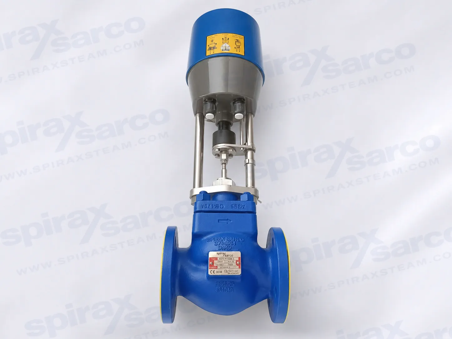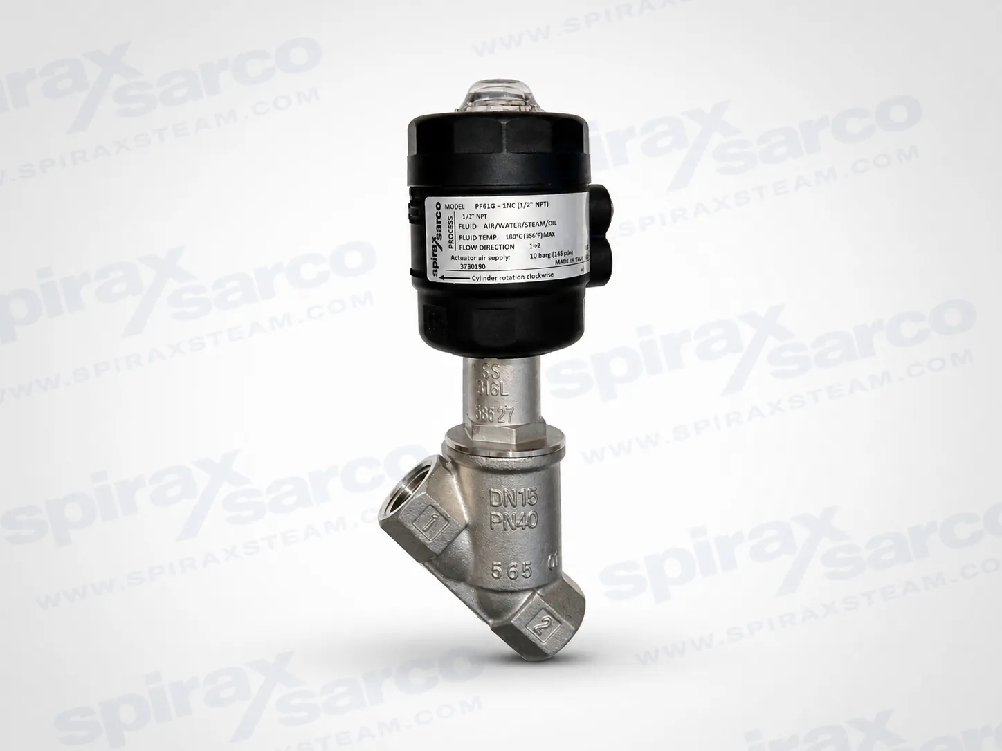
PF61G Stainless Steel Piston Actuated On/Off Valve
Stainless steel pneumatic piston actuated on/off valve with screwed BSP or NPT connections for steam, water, air, oil and gas duties.

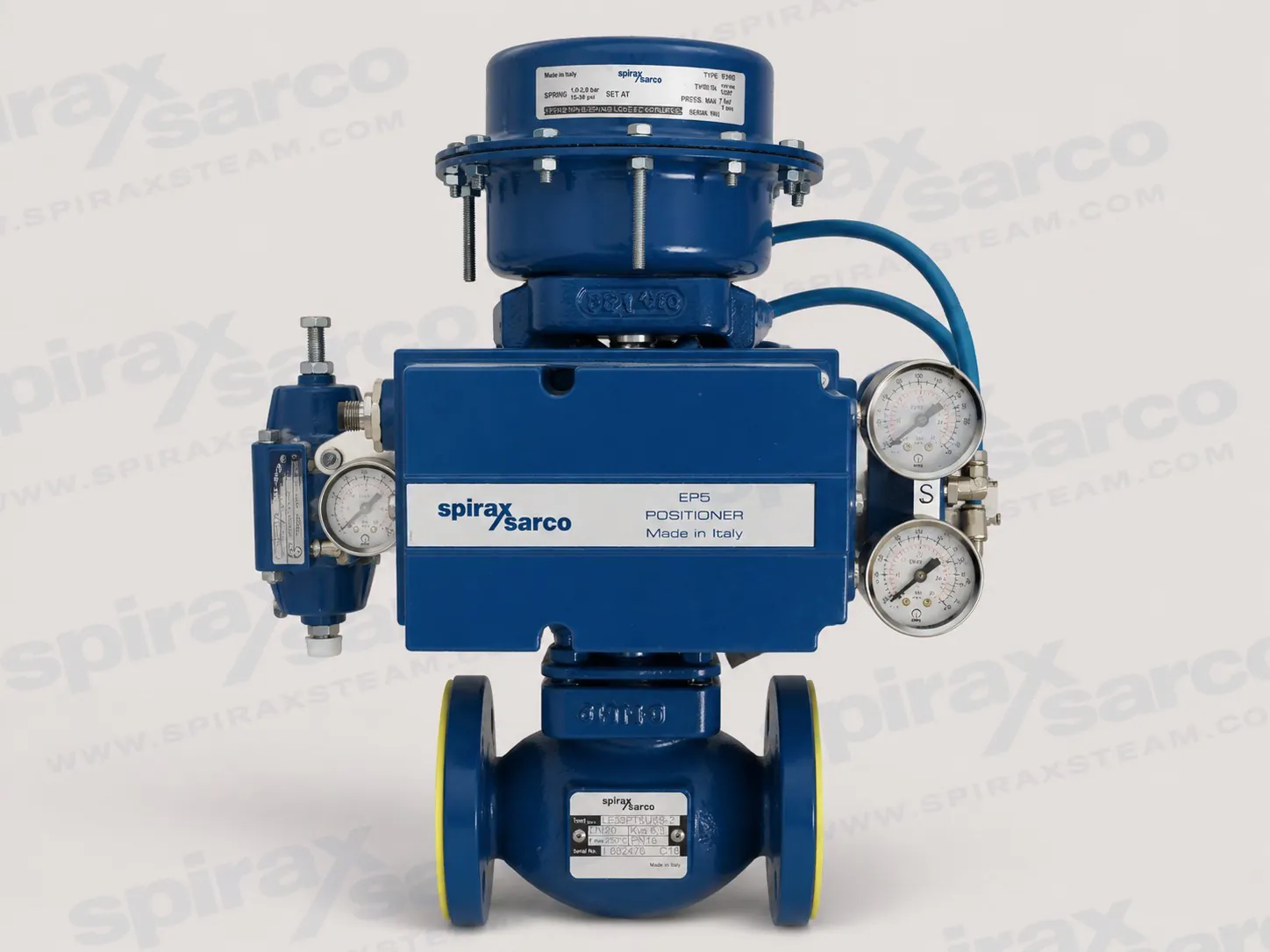
LE33
Spirax Sarco LE33 Two-port Control Valve
A legacy flanged PN16 two-port control valve documented in DN15 to DN100, with equal-percentage trim and verified installation and maintenance limits.
The Spirax Sarco LE33 is a legacy two-port control valve documented for flanged PN16 duties from DN15 to DN100. Its cast-iron body, equal-percentage characteristic and selectable metal or soft seat make it relevant where an installed LE33 must be identified, maintained or checked against its original operating limits.
This page is deliberately limited to LE33. The shared source manual also mentions other L-series valves, but their construction and ordering identities are not carried into the LE33 selection fields. Current availability and the final actuator pairing should be confirmed with Spirax Sarco before a new specification or replacement order is placed.
Documented size range: DN15 to DN100, with flanged connections and PN16 body design conditions.
Cast-iron body with stainless-steel plug, seat and stem.
Equal-percentage flow characteristic with 50:1 rangeability.
20 mm travel for DN15-DN50 and 30 mm travel for DN65-DN100.
Metal-to-metal leakage to IEC 534-4 Class IV at 0.01% of Kv, or Class VI with the documented soft-seat option.
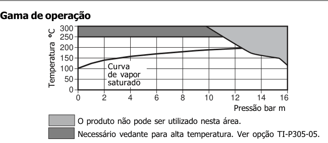
Standard maximum design temperature of 250 degC, with a documented high-temperature stem-seal option to 300 degC; minimum operating temperature is -10 degC.
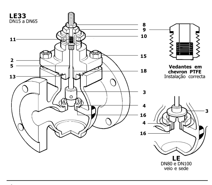
The valve should be installed in a horizontal pipeline with flow following the direction arrow cast on the body. The official instructions call for an upstream strainer; steam duties should also use an upstream separator and suitable condensate drainage where condensate can collect.
Maximum differential pressure is not a single valve-only value. It depends on the selected actuator and must be checked against the actuator technical information. Likewise, Kv is configuration-specific and must be confirmed from the installed valve label or the final sizing selection rather than inferred from the LE33 model alone.
Nominal size, flange standard and the required Kv.
Metal or soft seat and the required shut-off class.
Standard or high-temperature stem packing.
Actuator type, available thrust and allowable differential pressure.
Whether the duty remains within the documented pressure and temperature envelope.
For broader sizing and replacement comparisons, review the control valves range before confirming the final assembly.
The installation and maintenance guide below is based on an official legacy document. It remains useful for identifying construction, routine maintenance, tightening torques and safety precautions for installed LE33 valves, but it does not by itself establish current product availability.
Installation and commissioning
Maintenance
Technical details
Spare parts
Document scope: The source manual covers LE31 and LE33. This English web edition retains LE33 facts and procedures only; LE31 product data is intentionally excluded from this single-model page.
Install the valve in a horizontal pipeline with flow in the direction of the arrow cast on the body. Fit the valve into the pipeline in accordance with the applicable installation and maintenance instructions.
Always install a suitable strainer upstream of the control valve. On steam installations, install a separator upstream and provide a drain trap set where condensate can collect ahead of the valve.
Isolation valves are recommended upstream and downstream of the control valve, together with a manual regulating valve in the bypass. The bypass valve can then control the process while the control valve is isolated for maintenance.
Commission the actuator in accordance with the Spirax Sarco installation, maintenance and operating instructions supplied for that actuator.
Check pipeline connections and flange-bolt tightness. Where high-temperature graphite stem seals are fitted, tighten the gland nut by approximately one quarter turn. Do not overtighten because excessive friction can restrict the stem.
Visually inspect the seals for leakage and take corrective action where required. Replace worn PTFE chevron stem seals. For high-temperature graphite stem seals, tighten the gland by approximately one quarter turn without creating excessive stem friction. If adjustment cannot correct the leakage, replace the graphite packing.
Inspect the valve for wear or damage. Replace damaged stem and plug assemblies, seats and seals as necessary. High-temperature graphite packing is subject to normal operating wear and should be replaced during routine inspection to avoid premature seal failure.
Isolate the valve on both sides and confirm that trapped pressure has been safely relieved.
Remove the actuator in accordance with its instructions.
Undo the four bonnet nuts and remove the bonnet complete with stem and plug. Take care: pressurised fluid may remain trapped between the isolation valves.
Remove the locknut and gland. Withdraw the stem and plug, then discard the packing set and gland gasket.
Inspect all parts for damage or deterioration. Deposits or scoring on the stem will cause premature seal failure.
Clean the parts carefully without scratching the stem or gland bore. Refit the gland and stem.
Refit the bonnet with a new gasket, leaving the stem projecting. Fit the four nuts and tighten them to the table values while ensuring the plug is seated.
Fit the packing spring over the stem, renew the gland gasket, insert the new chevron seals without damaging their sealing lips, and fit a new guide.
Screw the gland down sufficiently to seat the gasket. Confirm that the stem moves freely, then refit the locknut.
Refit the actuator and mounting nut, connect the actuator to the stem, return the valve to service and check the packing for leakage.
Isolate the valve, safely relieve trapped pressure, remove the actuator and remove the bonnet assembly as described above.
Remove the locknut and gland, withdraw the stem and plug, and discard the old packing and gasket.
Inspect and clean all parts, renewing any damaged stem or plug components.
Install the lower support ring, graphite rings and upper support ring in their original sequence. Stagger adjacent ring joints by 90 degrees.
Insert the stem and plug carefully through the packing. Refit the bonnet with a new gasket, centre the plug in the seat and tighten the bonnet nuts to the specified torque.
Tighten the gland until it begins to compress the packing, then apply a further one and a half turns. Move the stem after each adjustment to bed the seals.
Refit the actuator and cycle the stem through its full travel at least five times. Apply the final gland adjustment specified by valve size, commission the actuator and check for leakage. Do not overtighten.
Isolate the valve on both sides, safely relieve trapped pressure, remove the actuator and remove the bonnet assembly.
Remove the locknut, gland, packing and bonnet gasket. Clean the bonnet and fit the replacement stem and plug assembly.
Unscrew the seat using the special tool available from Spirax Sarco for the valve size and type. Remove and renew the seat gasket.
Apply a small amount of silicone grease to the new seat thread, screw it into the body and tighten it to the specified torque.
Refit the bonnet with a new gasket, centre the plug in the seat and tighten the four bonnet nuts to the specified torque.
Install new chevron or graphite packing as applicable, verify free stem movement, refit the actuator and return the valve to service. Check the packing for leakage.
Plug design | Contoured, DN15-DN65; V-port, DN80-DN100 |
|---|---|
Metal-seat leakage | IEC 534-4 Class IV, 0.01% of Kv |
Soft-seat leakage | IEC 534-4 Class VI |
Flow characteristic | Equal percentage |
Rangeability | 50:1 |
Travel | 20 mm for DN15-DN50; 30 mm for DN65-DN100 |
Body design condition | PN16 |
Maximum design temperature | 250 degC standard; 300 degC with high-temperature stem seal |
Minimum operating temperature | -10 degC |
Cold hydraulic test pressure | 24 bar(g) |
Maximum differential pressure | Refer to the actuator technical information |
Size | DN15 | DN20 | DN25 | DN32 | DN40 | DN50 | DN65 | DN80 | DN100 |
|---|---|---|---|---|---|---|---|---|---|
Weight (kg) | 3.6 | 4.2 | 7.0 | 9.2 | 10.2 | 12.5 | 19.5 | 25.3 | 36.4 |
Part | Material | Standard |
|---|---|---|
Body | Cast iron | DIN 1691 GG25 |
Bonnet | Ductile iron | DIN 1693 Gr. GGG40.3 |
Plug, seat and stem | Stainless steel | BS 970 431 S29 |
Pin | Stainless steel | AISI 304 |
Gland and locknut | Stainless steel | BS 970 431 S29 / BS 6105 A4-80 |
Chevron packing | Virgin PTFE | PTFE |
Packing spring | Stainless steel | BS 2056 316 S42 |
Bonnet, gland and seat gaskets | Semi-rigid laminated graphite | - |
Bonnet studs and nuts | Steel | BS 4439 Gr. 8.8 / BS 3692 Gr. 8 |
Packing guide | Glass-reinforced PTFE | - |
Bonnet guide | Hardened stainless steel | AISI 440B |
Size | Seat (N m) | Bonnet nuts (N m) | Chevron gland (N m) |
|---|---|---|---|
DN15 | 40 +/- 5 | 15-20 | 25-30 |
DN20 | 53 +/- 3 | 20-25 | 25-30 |
DN25 | 80 +/- 5 | 25-30 | 25-30 |
DN32 | 130 +/- 5 | 40-45 | 25-30 |
DN40 | 220 +/- 5 | 40-45 | 25-30 |
DN50 | 150 +/- 5 | 60-65 | 25-30 |
DN65 | 300 +/- 12 | 47-53 | 32-38 |
DN80 | 400 +/- 16 | 55-61 | 32-38 |
DN100 | 600 +/- 24 | 45-51 | 32-38 |
Trapped pressure: Take care when removing the bonnet because pressurised fluid may remain trapped between isolation valves.
Packing leakage: Give immediate attention to leakage through the packing. Continued leakage can erode and damage the stem.
PTFE: PTFE is inert within its normal temperature range. If heated to its sintering temperature it can produce harmful fumes. Provide extraction close to the source and do not smoke where PTFE is handled. Prevent PTFE contamination of clothing and wash hands thoroughly.
Laminated gaskets: The reinforcing metal sheet is thin and sharp. Handle it carefully to prevent cuts to hands or fingers.
When ordering spare parts, quote the product code shown on the body label and use the documented spare-part description. Available assemblies include the actuator mounting nut, packing sets, stem and plug assembly, seat and gaskets, bonnet-gasket packs and graphite packing sets.
The source ordering example identifies LE33 as an L-series, two-port, equal-percentage valve with cast-iron body and flanged connection. The exact Kv, pressure class, stem-seal option and body-label code must be taken from the installed valve or confirmed with Spirax Sarco; they must not be inferred from the model alone.
Stainless steel pneumatic piston actuated on/off valve with screwed BSP or NPT connections for steam, water, air, oil and gas duties.
SG iron, equal-percentage Spira-trol control valve for DN125 to DN200 EN flanged process service, with standard, low-noise and anti-cavitation trim options.
| Document | Reference | Language | Download |
|---|---|---|---|
| LE33 MI P303 03 CH PT BR | - | Português | Download |