APT14HC is a flanged PN16 automatic pump trap with an SG iron body, DN50 x DN40 process connections and 8 litres nominal discharge per cycle for pressure-powered condensate removal under changing pressure or vacuum conditions.
APT14HC automatic pump trap
Spirax Sarco APT14HC is a flanged, steam-operated automatic pump trap for removing condensate from process plant when ordinary gravity or pressure-differential drainage is not reliable. It combines a displacement receiver, automatic trapping action and pressure-powered pumping in one PN16 unit. When process pressure is sufficient, condensate can discharge through the trap mechanism. When the process pressure falls below the return-system backpressure, the receiver fills, the internal snap-action mechanism admits motive steam and the condensate is pumped into the return line. This makes the APT14HC useful for temperature-controlled equipment, closed condensate returns, vacuum duties and installations where an electric pump would add unnecessary electrical or cavitation concerns.
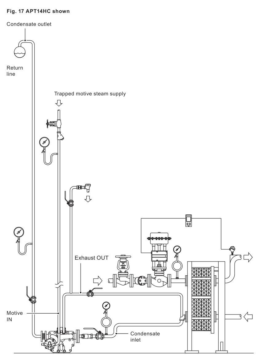
Official installation arrangement showing APT14HC in a condensate return system. The unit is shown with a trapped motive steam supply and a separate return line.
Why APT14HC is a distinct selection
The defining selection point is the larger flanged process path: the documented APT14HC configuration has a DN50 inlet and DN40 outlet, compared with smaller or different connection arrangements elsewhere in the product family. The local complete-unit reference identifies the PN16 flanged version with a 1/2 inch BSP motive steam connection and material code 16120456. That exact configuration is the only option exposed by this page. The pressure class, process connection size and outlet check-valve requirement must be confirmed together with the actual heat exchanger or process equipment before an order is placed.
The unit is operated by saturated or superheated motive steam and does not require electrical energy for its pumping cycle. The internal pump mechanism uses a stainless steel single-tension spring and snap-action linkage. Dual stainless steel floats operate a two-stage trap mechanism. This arrangement allows the APT14HC to change state quickly as condensate level and system pressure change, without an external shaft seal or gland. The documented design is a pressure-powered condensate solution, not a general-purpose electric transfer pump, so its suitability depends on motive pressure, total backpressure, available installation head and the condensate load.
How the pump-trap cycle works
During the filling part of the cycle, condensate enters through the inlet swing check valve and raises the floats. If the process pressure can overcome the return pressure, the two-stage trap opens and the unit behaves as an automatic trap. If the process pressure is lower than the total backpressure, the condensate remains in the main chamber instead of flooding back into the process equipment. The rising floats then operate the changeover linkage: the motive inlet opens and the exhaust closes. Motive steam raises the pressure in the chamber above the return pressure and forces the condensate through the outlet trap seat.
As the liquid level falls, the mechanism closes the motive inlet and opens the exhaust. The chamber pressure equalises through the exhaust connection and a new filling cycle begins. This operating principle allows the APT14HC to handle stalled heat exchangers and other low-differential-pressure conditions, including full-vacuum applications, provided the complete system is correctly sized and installed. The documented nominal pump discharge is 8 litres per cycle. Actual application capacity must be checked against installation head, motive pressure, total backpressure, process pressure and the required condensate load rather than inferred from the nominal cycle volume alone.
Application and operating boundary
APT14HC is a sensible route when the process equipment must drain while its pressure varies or falls below the condensate return pressure. Typical engineering reviews include temperature-controlled heat exchangers, air-heating equipment, vacuum equipment, closed condensate systems and low-level arrangements where condensate backup could reduce heat transfer or cause unstable process operation. The pressure-powered cycle can also avoid the motor, level switch and hot-condensate cavitation issues associated with conventional electric pumping arrangements.
The unit is safe for full vacuum conditions, but vacuum capability does not remove the need to size the return pipework or to provide a correctly connected balance line. The outlet line must be sized for the heat exchanger full-load condition, flash steam and any other equipment discharging into the same return. A separate DN40 DCV10 disc check valve is required between the APT14HC outlet flange and the connecting pipework flange. This is an installation requirement for the selected model and should be included in the system bill of materials.
The motive supply must be reliably controlled and kept dry. The installation manual recommends that the motive pressure is normally 3 to 4 bar g above the backpressure, although the product can use motive pressure up to 13.8 bar g. The motive line must be trapped and drained, and the supplied 100 mesh strainer must be kept clear. The balance line is connected from the exhaust port to the condensate outlet side of the equipment being drained and must connect to the top of the condensate pipe. These details are functional requirements: a blocked balance line, wet motive supply, wrong connection direction or an obstructed strainer can prevent the cycle from operating correctly.
Key parameters for selection
Flanged PN16 process connections: DN50 inlet x DN40 outlet.
SG iron body and cover to EN JS 1025 or ASTM A395.
Maximum motive inlet pressure: 13.8 bar g.
Maximum standard-pump backpressure: 5 bar g; consult Spirax Sarco for higher backpressure.
Maximum operating temperature for saturated or superheated steam service: 198 C at 13.8 bar g.
Ambient temperature range: -10 C to 200 C; lower temperature service requires consultation.
Safe for full vacuum conditions.
Nominal pump discharge: 8 litres per cycle.
Installation head: 0.2 m minimum with reduced capacity, 0.3 m recommended and 1 m maximum recommended.
Approximate unit weight: 65 kg; allow at least 275 mm withdrawal distance for cover maintenance.
Installation and ordering checks
Before selecting Spirax Sarco APT14HC, collect the installation head from the pump base to the process outlet, motive steam pressure, total condensate return backpressure, process operating pressure, maximum steam or condensate load and the relevant minimum and maximum secondary-fluid temperatures. Full capacity selection is application-specific. Do not treat the 8 litre cycle volume as a guaranteed flow rate.
Provide at least 0.2 m installation head from the pump base; 0.3 m is recommended and a 1 m height is the maximum recommended in the technical information. The inlet pipe should provide a reservoir for the discharge cycle and should be positioned at least one pipe diameter below the process outlet while remaining as high as practicable above the pump inlet. A throttling isolation valve may be required during cold start-up if hydraulic pulsing occurs at the inlet check valve.
Confirm the flange standard before ordering. The technical information lists PN16, JIS/KS 10 and ASME 150 flanged connection options, while the local complete-unit reference for this page is PN16 with a 1/2 inch BSP motive steam connection. Electroless nickel plating of the body and cover and preparation for sight-level gauges are optional arrangements that must be specified at order; a sight-level gauge cannot be retrofitted to the standard unit. EN 10204 3.1 certification is available when certification requirements are stated at the time of order.
For the wider selection context, return to mechanical condensate pumps. For an explanation of pressure-powered condensate removal and related application choices, review the condensate pump topic. Where the duty is a conventional receiver-led return rather than a pump-trap cycle, compare electrical condensate pumps.
What to confirm before commissioning
Check that the process inlet, condensate outlet, motive steam and exhaust connections follow the flow arrows and marked ports. Confirm that the motive steam line is trapped, drained and filtered; the condensate inlet strainer is clean; the balance line is open and not waterlogged; and the DN40 DCV10 is centred between the outlet flanges with its flow arrow pointing toward the return. Isolate and safely depressurise all steam and condensate lines before installation or maintenance, allow hot components to cool, and use a competent person for lifting and commissioning. The complete installation must be assessed for motive-steam temperature rise, possible steam backflow through the balance line, sight-glass temperature gradients and any hazardous or explosive process media.
After these checks, order Spirax Sarco APT14HC against the confirmed flange standard, motive connection and application sizing data. These checks keep the page specific to the documented model and its flanged complete-unit configuration rather than substituting a similar model name or nominal pipe size alone.
Description
APT14HC is a flanged displacement receiver pressure rated to PN16. It automatically traps or pumps according to pipeline conditions and is operated by saturated or superheated motive steam. It is used to remove condensate from process plant under operating conditions including vacuum.
Definition of motive steam
In this document, motive steam means saturated steam or superheated steam used to operate the pump trap.
Design, standards and certification
The shell is designed in accordance with A.D. Merkblatter/ASME VIII.
The product complies with the requirements of the European Pressure Equipment Directive 2014/68/EU and ATEX Directive when applicable, and carries the relevant marks when required.
Certification to EN 10204 3.1 is available. Certification and inspection requirements must be stated at order placement.
Sizes and connections
Item
APT14HC data
Body material
SG iron
Process connections
Flanged DN50 inlet x DN40 outlet
Flange standards
EN 1092 PN16, JIS 10 (JIS B 2210), KS 10 (KS B 1511) or ASME B 16.5 150, subject to the selected connection
Motive / exhaust
DN15 (1/2 in), BSP T Rp (ISO 7-1) or NPT
Sight glass connection
DN15 (1/2 in), BSP T Rp (ISO 7-1) or NPT
Drain connection
DN10 (3/8 in), BSP T Rp (ISO 7-1) or NPT
Pressure and temperature limits
Limit
Metric value
Qualification
Body design conditions
PN16
Maximum motive inlet pressure
13.8 bar g
200 psi g
PMA maximum allowable pressure
16 bar g at 120 C
232 psi g at 248 F
TMA maximum allowable temperature
300 C at 12.8 bar g
572 F at 186 psi g
Minimum allowable temperature
-10 °C
Consult Spirax Sarco for lower temperatures.
PMO maximum operating pressure
13.8 bar g at 198 °C
Saturated and superheated steam service
Maximum backpressure for standard pumps
5 bar g
Consult Spirax Sarco for higher backpressures.
TMO maximum operating temperature
198 C at 13.8 bar g
Saturated and superheated steam service
Ambient temperature limits
-10 C to 200 C
Vacuum
Safe under full vacuum conditions
Maximum cold hydraulic test pressure
24 bar g
This is a test pressure, not an operating limit.
Filling and installation head
Condition
Value
Recommended filling head above the pump
0.3 m from the base of the receiver / process
Minimum installation head
0.2 m from the base of the pump; reduced capacity applies
Maximum recommended installation head
1 m from the base of the pump; consult Spirax Sarco for higher heads
Materials
Part
Material
Material standard or grade
Cover
SG iron
EN JS 1025 or ASTM A395
Cover gasket
Graphite laminated with stainless steel insert
Body
SG iron
EN JS 1025 or ASTM A395
Cover bolts
Stainless steel
ISO 3506 Gr. A2 70
Pump lever, floats and trap lever
Stainless steel
BS 1449 304 S15
Inlet check-valve seat
Stainless steel
AISI 420
Inlet check-valve flap
Stainless steel
BS 3146 ANC 4B
Pump mechanism bracket
Stainless steel
BS 3146 ANC 4B
Pump spring
Stainless steel
BS 2056 302 S26 Gr. 2
Exhaust seat
Stainless steel
BS 970 431 S29 or ASTM A276 431
Exhaust valve
Stainless steel
BS 3146 ANC 2
Valve seat gasket
Stainless steel
BS 1449 409 S19
Actuator arm
Stainless steel
BS 3146 ANC 2
Drain plug
Steel
DIN 17440 1.4571
Motive strainer
SG iron
External DCV10 outlet check valve
Stainless steel
Required for the DN40 condensate outlet
Trap mechanism materials
Part
Material
Material standard or grade
Trap second-stage valve
Stainless steel
ASTM A276 440 B
Trap housing
Stainless steel
BS 3146 ANC 2
Split pin
Stainless steel
BS 1574
Trap housing bolt
Stainless steel
BS 6105 A4 80
Trap first-stage valve
Stainless steel
BS 970 431 S29 or ASTM A276 431
O-ring
EPDM
Dimensions and weight
Approximate dimensions are in millimetres (inches) and the weight is in kilograms (pounds). A, B, C, D, E, F and G refer to the dimensional drawing; H is the cover withdrawal distance, I is the flange dimension and J is the pump height.
Dimension
PN16
JIS / KS 10
ASME 150
A
512 mm (20.1 in)
506 mm (19.9 in)
524 mm (20.6 in)
B
198 mm (7.7 in)
C
270 mm (10.6 in)
D
400 mm (15.7 in)
E
335 mm (13.1 in)
F
261 mm (10.2 in)
G
57 mm (2.24 in)
H withdrawal
275 mm (10.8 in)
I
31.5 mm (1.2 in)
31.5 mm (1.2 in)
45 mm (1.8 in)
J
198 mm (7.8 in)
Weight
Approximately 65 kg (143 lb)
Nominal capacity
For full capacity details, consult Spirax Sarco for the specific application. Sizing requires the installation head, available motive steam pressure, total condensate return backpressure, process operating pressure, maximum heat load and the relevant secondary-fluid temperatures.
Model
Pump discharge per cycle
APT14HC
8 litres
How to specify and order
The pump trap shall be a Spirax Sarco automatic pump trap type APT14HC operated by steam to 13.8 bar g. No electrical energy shall be required. The body shall be SG iron to EN JS 1025 dual certified with ASTM A395, with a swing-type inlet check valve. The internal trap mechanism shall contain dual stainless steel floats connected to a two-stage trap, while the internal pump mechanism shall be a stainless steel single-tension-spring snap-action device with no external seals or glands.
Example local complete-unit reference: one APT14HC automatic pump trap, DN50 x DN40, flanged EN 1092 PN16 with a 1/2 inch BSP motive steam connection, material code 16120456.
Optional extras
The body and cover can be specified with electroless nickel plate. This must be stated at order placement.
The body can be drilled, tapped and plugged to accept sight-level gauges. This preparation must be specified at order; sight-level gauges cannot be fitted retrospectively to the standard unit.
Installation and Maintenance Guide
This target-scoped guide reorganises the official IM-P612-04 CMGT Issue 15 instructions for APT14HC. The full English manual remains available as the product attachment. Installation, commissioning and maintenance must be carried out or supervised by competent personnel in accordance with local regulations and site procedures.
1. Safety information
Isolation and pressure: Before installation or maintenance, isolate all steam, condensate and motive lines. Safely relieve residual internal and line pressure to atmosphere. Do not assume a system is depressurised because a gauge reads zero. Consider double isolation, locking or labelling of closed valves and controlled opening of isolation valves.
Temperature: Allow the product and connecting pipework to cool after isolation. External surfaces can reach 200 C at the maximum permitted operating condition. The product is not self-draining, so take care when dismantling or removing it.
Handling: Assess the mass and lifting environment before moving the approximately 65 kg unit. The lifting holes, where provided, are used at the purchaser's sole risk and responsibility. Select suitable lifting hardware and ensure operators are competent.
Process hazards: Use appropriate protective clothing for chemicals, temperature, pressure, falling objects and eye or face hazards. If pumping potentially explosive media, use an inert motive medium with no oxygen present. Assess condensate temperature rise, steam backflow through the balance line and the temperature gradient seen by any sight glass.
2. General product information
APT14HC is a flanged PN16 displacement receiver operated by saturated or superheated motive steam. It automatically traps or pumps according to pipeline conditions and can remove condensate under vacuum. The body and cover are SG iron. Optional electroless nickel plating and sight-level-gauge preparation must be specified at order; a sight-level gauge cannot be retrofitted to the standard unit.
2.1 Pressure and temperature limits
Limit
APT14HC value
Maximum motive inlet pressure
13.8 bar g (200 psi g)
Maximum allowable pressure
16 bar g at 120 °C (232 psi g at 248 °F)
Maximum allowable temperature
300 °C at 12.8 bar g (572 °F at 186 psi g)
Minimum allowable temperature
-10 °C (14 °F); consult Spirax Sarco for lower temperatures
Maximum operating pressure
13.8 bar g at 198 °C (200 psi g at 388 °F)
Maximum standard-pump backpressure
5 bar g (72.5 psi g); consult Spirax Sarco for higher backpressures
Maximum operating temperature
198 °C at 13.8 bar g (388 °F at 200 psi g)
Ambient temperature
-10 °C to 200 °C (14 °F to 392 °F)
Maximum cold hydraulic test pressure
24 bar g (348 psi g)
3. Operating principle
Condensate enters through the inlet swing check valve and raises the dual floats.
When process pressure is sufficient to overcome total return backpressure, the two-stage trap opens and condensate discharges.
When process pressure is lower than return backpressure, condensate fills the chamber and raises the floats until the changeover linkage operates.
The motive inlet opens and the exhaust closes. Motive steam raises the chamber pressure above the total backpressure and forces condensate through the outlet trap seat.
As the liquid level falls, the motive inlet closes and the exhaust opens.
The chamber pressure equalises through the exhaust line and the filling and trapping cycle begins again.
The outlet must include a separate DN40 DCV10 disc check valve between the pump outlet flange and connecting pipework flange. The directional arrow must point in the direction of condensate flow.
4. Installation warnings
When motive steam is much hotter than the condensate, design the downstream system for the resulting temperature difference.
Control motive pressure reliably so the temperature of the system and connected equipment remains within its allowable limits.
Assess the possibility of steam backflow through the balance line and ensure upstream equipment can withstand the motive-steam temperature.
Specify sight glasses for the maximum temperature gradient between the hottest possible steam and the coldest condensate.
5. Installation arrangement
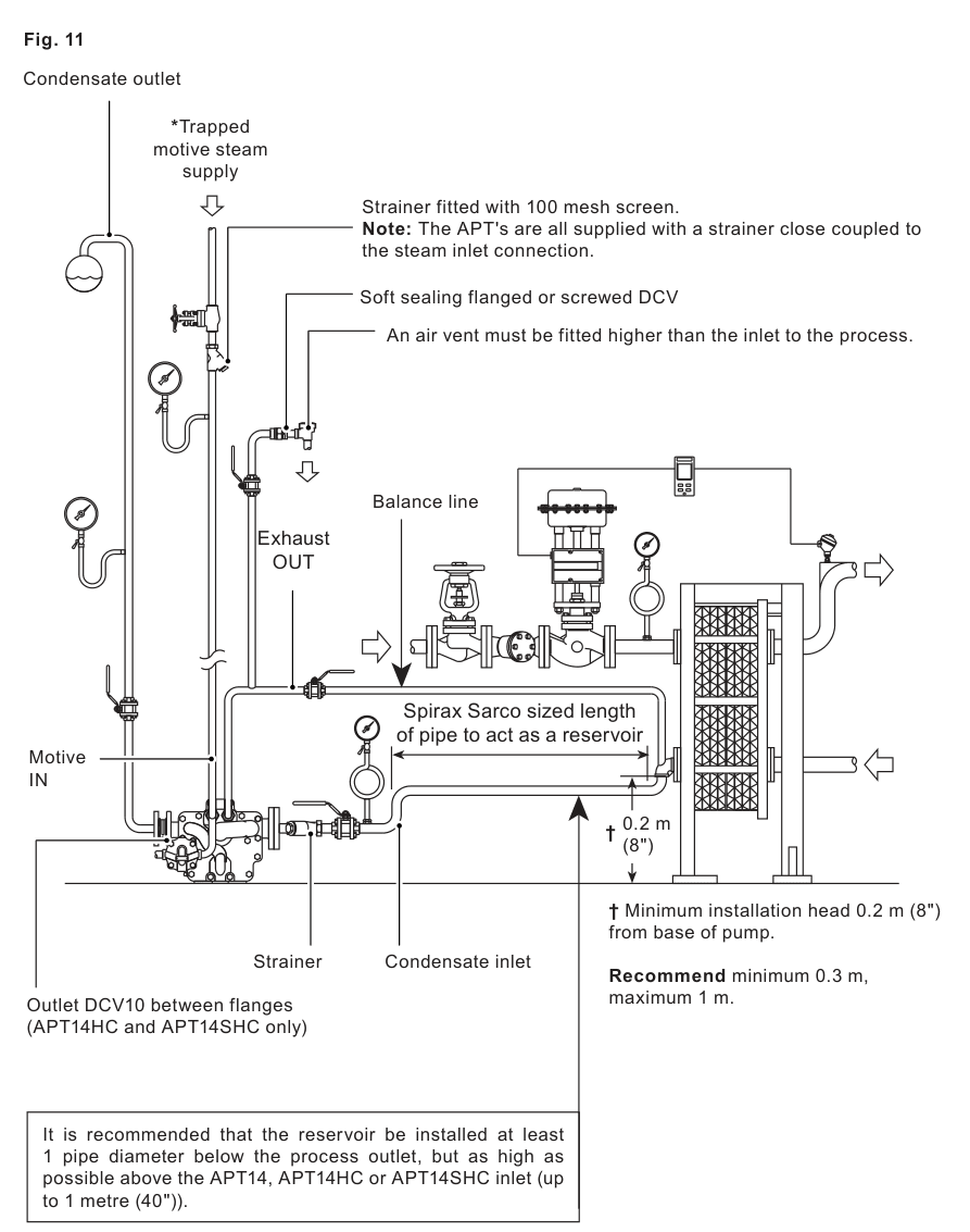
APT14HC system arrangement from the official installation manual. The diagram shows the trapped and filtered motive supply, balance line, inlet reservoir, 0.2 m minimum head, recommended 0.3 m head, 1 m maximum recommended head and the DN40 DCV10 between outlet flanges.
5.1 Inlet piping
Size the inlet pipework to accumulate condensate during the pump discharge cycle and prevent condensate backing up into the process equipment. For APT14HC, allow a reservoir for the 8 litre cycle value. Position the reservoir at least one pipe diameter below the process outlet but as high as practicable above the pump inlet, up to 1 m. Fit a Spirax Sarco Y-type strainer at the condensate inlet and keep the mesh clean.
5.2 Installation head
Provide at least 0.2 m from the base of the pump, with reduced capacity at the minimum. The recommended installation head is 0.3 m and the maximum recommended installation head is 1 m. During cold start-up, hydraulic pulsing of the inlet check valve may occur; a throttling isolation valve can be used to reduce filling pressure.
5.3 Connections
The DN50 process inlet is connected to the equipment being drained and the DN40 outlet is connected to the condensate return. Follow the flow arrows. Connect the DN15 (1/2 in) port marked S to a trapped motive steam supply. Drain this line continuously through a suitable steam trap and keep it filtered by the supplied 100 mesh strainer. Connect the DN15 (1/2 in) port marked E as the balance line back as close as possible to the condensate outlet of the equipment. Connect the balance line to the top of the condensate pipe and keep it open and free from waterlogging.
5.4 Outlet piping
Size the outlet pipework for flash steam at the heat exchanger full-load operating condition and for any other equipment discharging into the return line. Fit the separate DN40 DCV10 centrally between the outlet flanges, with a gasket on both sides and the flow arrow in the direction of condensate flow. Refer to IM-P601-32 for the separate DCV10 maintenance and technical information.
5.5 Pressure gauges and motive pressure
Pressure gauges are recommended on the motive supply, condensate inlet and condensate outlet. Although APT14HC can use motive pressure up to 13.8 bar g, the motive pressure should normally be 3 to 4 bar g above the backpressure. If a pressure-reducing valve is used, consider pulsating flow. The motive supply must be drained by a suitable steam trap so the motive steam remains dry.
6. Commissioning
Confirm that process inlet, condensate outlet and motive/exhaust connections follow the installation arrangement and flow arrows.
Slowly open the motive steam inlet. Confirm that the steam supply is trapped, drained and filtered, and that the exhaust/balance line is open and unrestricted.
Slowly open the condensate inlet and discharge isolation valves and allow condensate to fill the body.
When the process is operating, the unit should discharge condensate under the available pressure conditions into the return line.
If the unit does not operate, recheck motive pressure versus total backpressure, connection orientation, strainers, installation head and balance-line condition before using the fault-finding guide.
7. Maintenance
Inspect the APT14HC periodically according to the application. Before maintenance, isolate all steam and condensate lines, relieve residual pressure, allow hot parts to cool and wear suitable protective clothing. The snap-action mechanism can move suddenly; handle the cover assembly and internal mechanism carefully.
7.1 Cover assembly removal and inspection
Disconnect the cover connections and remove the cover bolts using the correct socket.
Slide the cover assembly away from the body. Allow a minimum withdrawal distance of 275 mm for APT14HC, then lift the cover to a secure work surface without damaging the gasket face.
Check the mechanism for dirt, scale, damage and free movement. Inspect the spring, valves, floats, inlet swing check-valve flap and the two-stage trap module.
Replace damaged or malfunctioning parts with genuine replacement parts and follow the detailed procedure in the full manual.
7.2 Reassembly
Fit a new gasket where required and align the cover and body gasket faces carefully. Tighten the cover bolts sequentially in opposing pairs, gradually increasing to 63 ± 5 N m (46.5 ± 4 lbf ft) for the M12 x 45 bolts using a 19 mm A/F socket. The pump bracket M8 bolts are tightened to 18 ± 2 N m using a 13 mm A/F socket where that repair procedure is required. Reconnect the motive and exhaust lines to the ports marked S and E and reinstate the motive supply strainer with its 100 mesh screen before recommissioning.
8. Fault-finding guide
Installation and troubleshooting must be performed by qualified personnel. Check the following first: all isolation valves open; condensate inlet and motive supply strainers clean; installation head greater than 0.2 m; motive pressure higher than total backpressure; balance line connected to the equipment outlet and free from obstruction; and flow direction correct.
Symptom
Likely cause
Check or remedy
APT14HC fails to operate at start-up
No motive pressure
Confirm motive pressure exceeds total backpressure, the supply is not isolated and the motive strainer is clean.
APT14HC fails to operate at start-up
Closed inlet or incorrect S/E connection
Open the condensate inlet and confirm motive is connected to S and exhaust to E.
Equipment flooded while the unit cycles
Unit undersized
Check the system parameters against the application sizing sheet or graph and consult Spirax Sarco.
Equipment flooded and unit stopped
Blocked balance, inlet or outlet line
Clear the balance line, clean the relevant strainer and inspect the return line for blockage.
Equipment flooded and unit stopped
Damaged mechanism, leaking motive valve or broken spring
Isolate safely and inspect the mechanism, motive inlet valve, spring and floats according to the maintenance procedure.
Chattering during cold start-up
Hydraulic pulsing at the inlet check valve
Reduce the installation head or install a throttling valve on the condensate inlet.
Chattering in the return line after discharge
Live steam entering the discharge line
Ensure the motive supply trap discharges to a non-flooded return and that the return is adequately sized.
9. Disposal and return
No hazardous construction materials are identified in the manual. Recycle or dispose of unwanted material according to local requirements. Before returning a product, provide written information about contamination residues, mechanical damage and any associated health, safety or environmental hazards.