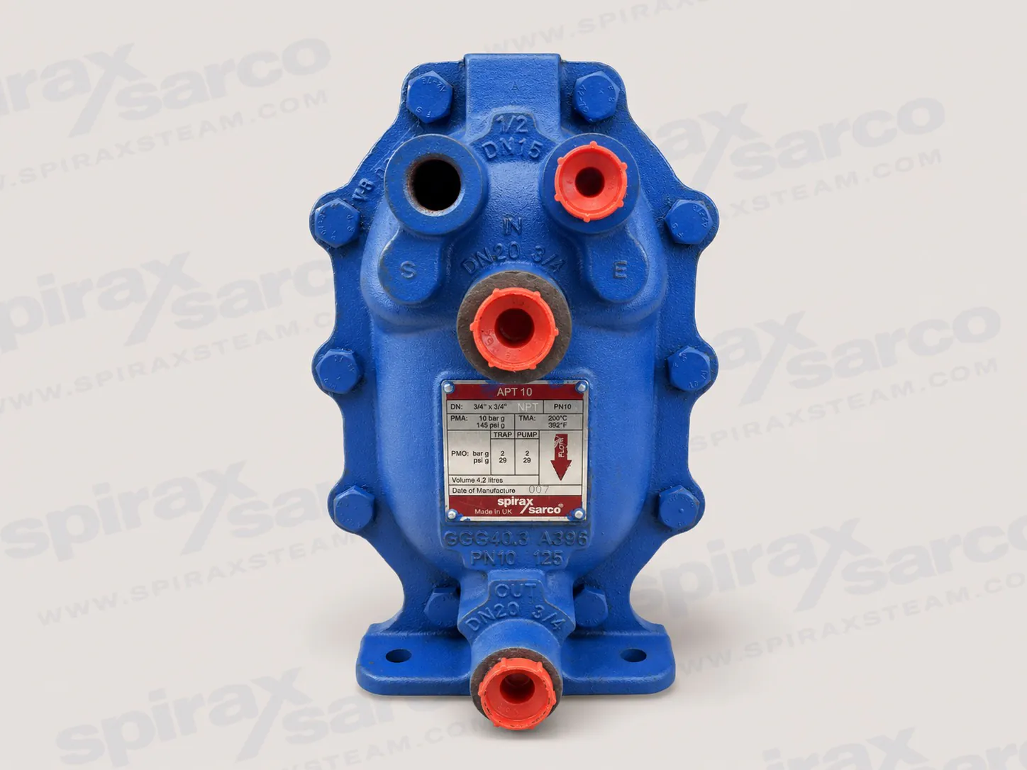
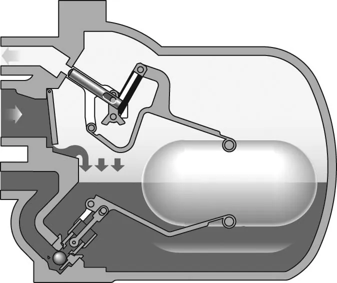
APT10-4.5 automatic pump trap for condensate removal when differential pressure changes
The Spirax Sarco APT10-4.5 automatic pump trap combines a steam trap and a pressure-powered condensate pump in one screwed, PN10 displacement receiver. It is intended for process and heating plant that must remove condensate even when the pressure relationship across a conventional steam trap is not constant. In normal drainage conditions, the APT10-4.5 discharges condensate as a float-controlled trap. When return-line backpressure rises, inlet pressure falls, or the drained equipment operates under vacuum, the same unit changes to pumping mode and uses motive steam to move condensate into the return system.
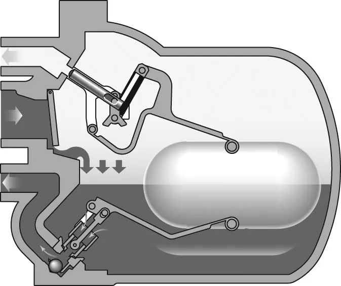
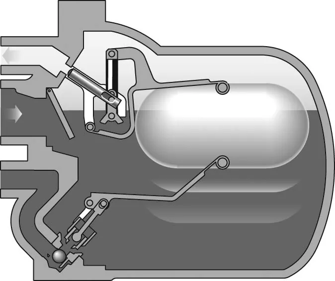
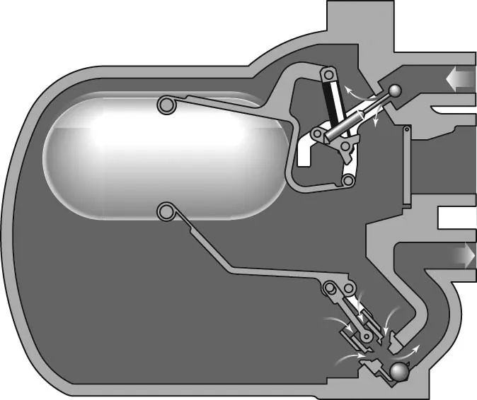
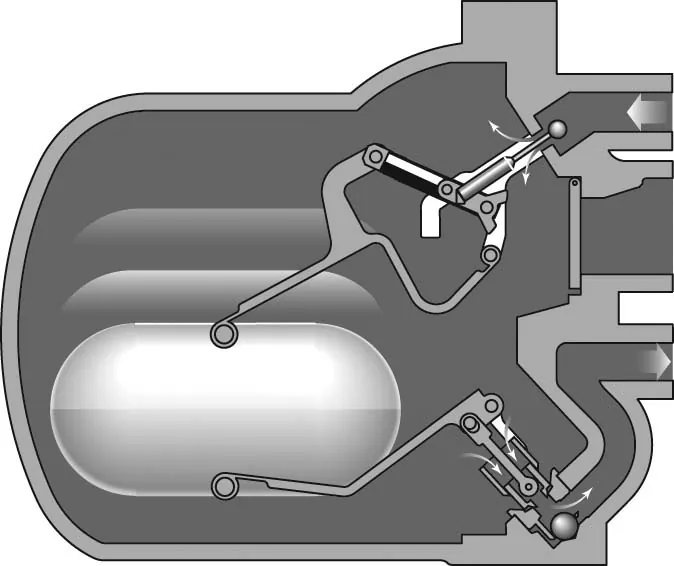
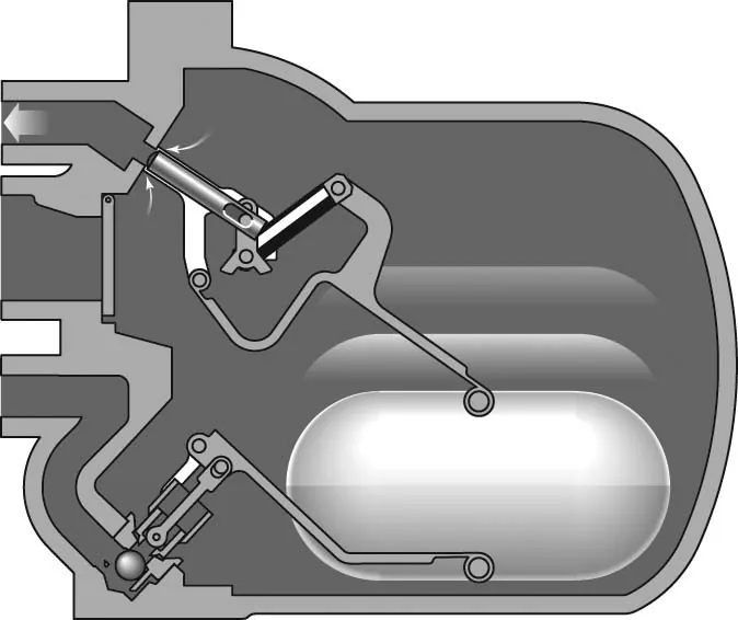
That automatic changeover addresses a familiar system problem: a temperature-controlled heat exchanger can lose the differential pressure that an ordinary trap needs to drain. The heat exchanger may then retain condensate, with consequences for heat transfer and control. The APT10-4.5 is designed so the condensate level can continue to control the mechanism. If the inlet pressure is sufficient to overcome the return backpressure, condensate leaves through the trap mechanism. If it is not, the float rises in the main chamber until the changeover linkage opens the motive-steam inlet and closes the exhaust valve. Motive steam raises the pressure in the body above the total backpressure, forcing condensate to the return line. As the liquid level falls, the linkage restores the exhaust condition and the cycle begins again.
One body for trapping, pumping and non-return protection
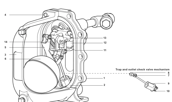
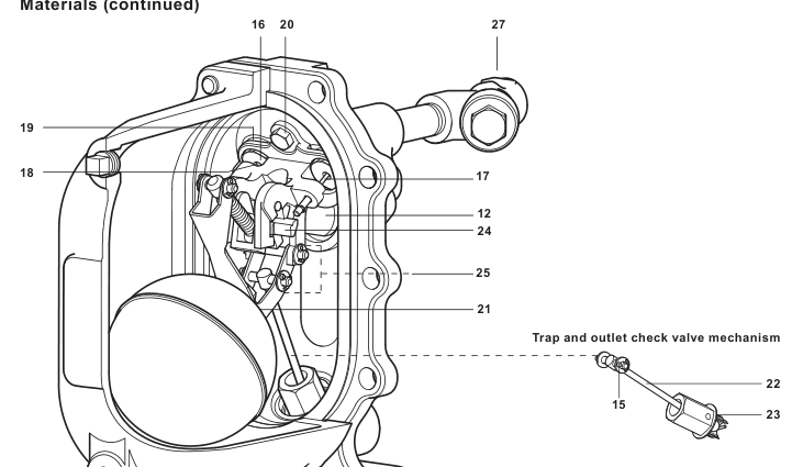
The APT10-4.5 is not a conventional electrically driven receiver-and-pump package. Its pumping action is driven by steam, so the documented product does not require electrical energy for its operating cycle. The construction places the pump, internal trap and check-valve functions inside the same body envelope. The official technical information identifies an SG-iron body and cover, a stainless-steel float, a swing-type inlet check valve and a ball-type outlet check valve. The design also avoids external seals and glands. These features matter because they define how the product manages filling, discharge and return-flow prevention as a single mechanical arrangement rather than as separate devices assembled in the field.
During the filling part of the cycle, condensate enters through the inlet swing check valve and lifts the float. The float is connected to the internal trap mechanism by a lever-and-pivot arrangement. During a pumping discharge, the outlet ball check valve prevents condensate from running back into the main chamber. The motive inlet and exhaust valves change state through a snap-action mechanism. This is why the installation and maintenance guide requires careful handling during dismantling: the mechanism is functional hardware, not a passive body fitting.
The compact, mechanically integrated arrangement can be useful where a project needs a non-electric response to condensate back-up but does not have the space or duty profile for a separate receiver and motor pump. It does not remove the need for system design. Motive-steam availability, return-line pressure, available installation head and the actual condensate load remain decisive. The APT10-4.5 should be selected as a component of the condensate system, not simply as an interchangeable replacement for a standard trap.
Where the APT10-4.5 fits
The documented application is condensate removal from process and heating plant under all operating pressure conditions, including vacuum. It is particularly relevant where pressure-controlled or temperature-controlled equipment can see a reduced or reversed differential pressure between the drainage point and the condensate return. Typical engineering questions include whether the equipment outlet will be above the pump-trap inlet, whether flash steam will raise return-line backpressure, and whether the motive supply remains available when the process is operating at its most difficult drainage condition.
The product is specified for steam, air and water or condensate within the stated fluid group. Any proposed use with another fluid requires a suitability check. This boundary is important: an automatic pump trap solves a particular condensate-handling problem, but it is not a general fluid-transfer pump with unrestricted media compatibility. The selected installation guide also limits the illustrated installation to closed-loop steam systems. Where the project starts with a broader recovery question rather than a model requirement, review Spirax Sarco condensate pumps before making a final product selection.
In a controlled heat-transfer application, the useful distinction is between two states. When upstream condensate pressure exceeds the pressure at the return connection, the unit traps normally and the float modulates the internal trap. When the system pressure at the condensate inlet is lower than the return backpressure, an ordinary trap can stall and the drained equipment can flood. The APT10-4.5 is designed to let condensate fill its chamber, then use motive steam to discharge it. It returns to the trapping state after the level falls and the exhaust valve equalises the body with the inlet condition. This automatically repeated sequence is the core reason to consider an automatic pump trap instead of a trap alone.
Operating envelope and connection choices
The body design condition is PN10. The official technical information states a maximum motive inlet pressure of 4.5 bar g, a maximum operating pressure of 4.5 bar g and a maximum backpressure of 4.0 bar g. The published operating-temperature range is -10 to 155 °C, with ambient limits of -10 to 200 °C and a maximum cold hydraulic test pressure of 15.0 bar g. These limits should be assessed together with the actual system design rather than treated as isolated catalog figures. For example, total backpressure can include the return-line pressure, the static lift contribution and frictional losses. Motive pressure must provide enough margin to overcome that total condition while remaining within the product limit.
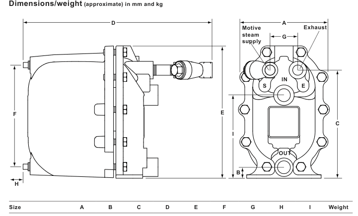
The fluid connections are DN20 inlet and DN20 outlet, with DN15 motive and exhaust connections. The selected technical information documents BSP and NPT connection options. The physical arrangement is therefore part of the order definition: the order example specifies the DN20 x DN20 unit and the motive-fluid connection form. Project documentation should also state any required inspection or certification requirement at the time of order, since the technical information notes that EN 10204 3.1 certification is available when specified at order placement.
Do not select the unit only by nominal connection size. The sizing data required by the manufacturer includes the installation head from the pump base to the process condensate outlet, the available motive-steam pressure, total condensate-return backpressure, the heat exchanger's full-load operating pressure and maximum steam load, plus the minimum and maximum controlled temperatures of the secondary fluid. This combination establishes whether the pump-trap can move the required condensate flow at the actual pressure condition. The detailed technical section preserves these inputs and the original dimensional data for formal review.
Installation conditions that affect the result
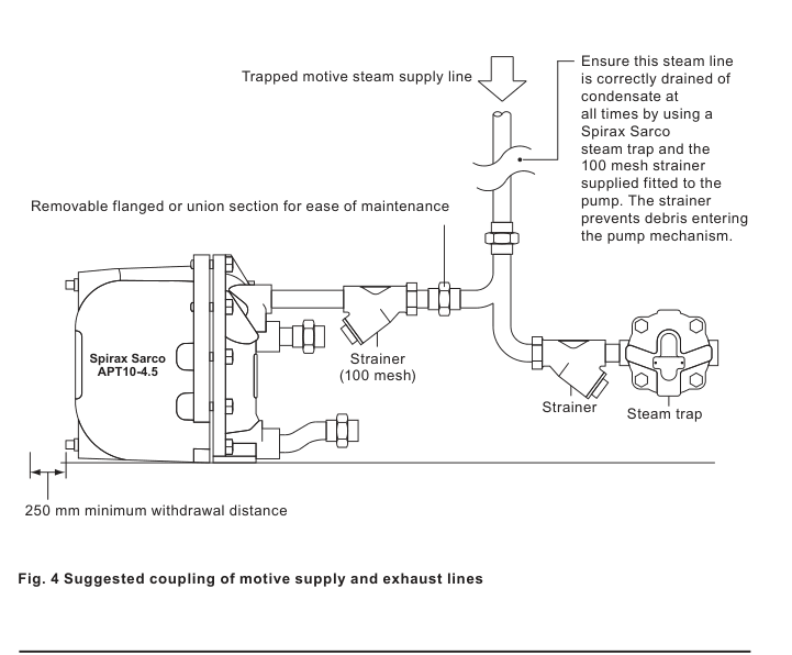
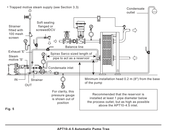
The APT10-4.5 requires installation head. The official guide gives 0.2 m from the base of the pump as the minimum and 0.3 m as the recommended installation head; operation at the minimum reduces capacity. The inlet pipework should provide enough reservoir volume to hold condensate while the pump is discharging. The guide specifies a condensate-inlet Y-type strainer with a maximum 0.8 mm perforation screen. It also requires a trapped, filtered motive-steam supply and an exhaust balance line connected to the top of the condensate pipe as close as possible to the outlet of the equipment being drained.
These requirements are functional rather than cosmetic piping preferences. A restricted exhaust or balance line can stop cycling. A blocked inlet strainer can prevent filling. Outlet pipework must account for flash steam at full heat-exchanger load so that excess backpressure is not created. The detailed installation section retains the official line diagrams, the port designations `IN`, `OUT`, `S` and `E`, the commissioning sequence and the fault-finding guide. Installation and maintenance must be performed by qualified personnel with the pressure isolated and vented, hot surfaces cooled, suitable protective equipment in use and appropriate lifting arrangements in place.
Ordering, maintenance and project confirmation
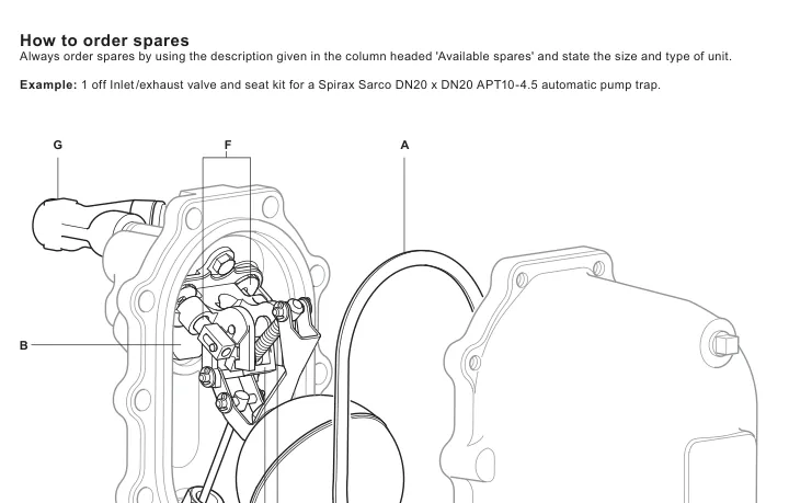
For an inquiry, identify the product as an APT10-4.5 automatic pump trap and confirm the DN20 x DN20 fluid connection arrangement, the BSP or NPT thread choice, and the motive-fluid connection form. Confirm the available head, motive pressure, total backpressure, process load and fluid boundary before placing an order. State any inspection or EN 10204 3.1 certification requirements at that time. The official documentation also identifies replaceable cover-gasket, inlet-check-valve, spring-and-actuator-arm, float, trap-and-outlet-check-valve, inlet/exhaust-valve-and-seat, and motive-strainer service items.
Use genuine Spirax Sarco replacement parts and follow the documented torque values and assembly sequence. The APT10-4.5 has an adjustment-free valve mechanism, but that does not make disassembly routine. The maintenance instructions call out the spring mechanism, the need for new split pins and washers where specified, gasket alignment, clean sealing faces and final functional movement of the float. The technical and installation information below provide the detailed source record for design, installation, commissioning and service decisions.