
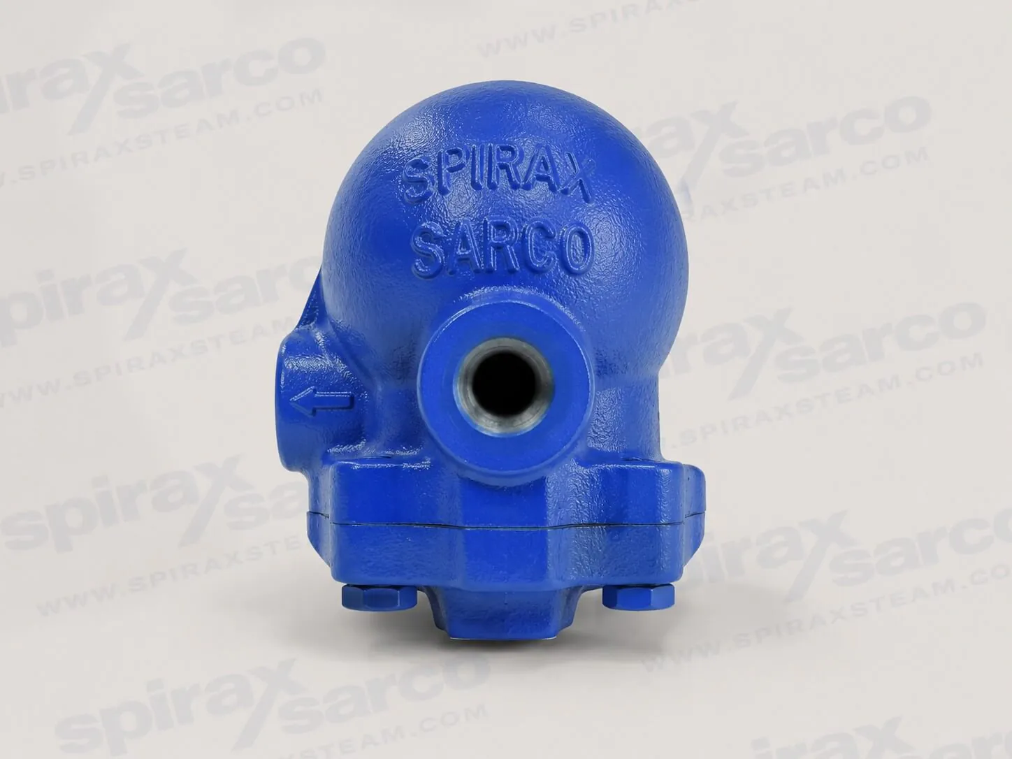
CA14
CA14 SG Iron Air and Gas Trap
Float-type SG iron automatic liquid drainer for Group 2 air and gas systems, with a Viton valve cone, continuous discharge and screwed or selected flanged connections.
CA14 SG iron air and gas trap for continuous liquid drainage
The Spirax Sarco CA14 is a float-type automatic liquid drainer for air and gas systems. It is intended to remove condensate or other drained liquid while retaining the pressurised gas in the system. The product uses an SG iron body and cover, a float-operated internal mechanism and a Viton main valve cone. It is a continuous-discharge design: liquid entering the chamber raises the float and opens the main valve, while air or gas lowers the float and allows the valve to close tightly on its seat. This operating sequence is useful where a low point, receiver, separator, aftercooler or similar item must be kept clear of accumulated liquid without relying on manual draining.
CA14 is an air and gas trap, not a steam trap. Its documented duty is air or gases within PED Group 2. It is not suitable for PED Group 1 liquids or gases. That distinction is important when a system uses compressed air, an industrial gas or a changing liquid load: the model should be selected from the actual fluid group, pressure, temperature and drainage arrangement rather than from a generic trap label. The technical information and the installation guide below preserve the formal product limits and the safety conditions that must be checked before installation.
Why a float-operated liquid drainer is used
The principal engineering advantage of a float mechanism is its response to the liquid level in the body. There is no need to wait for a thermostatic element to react or for a timed device to cycle before the discharge valve can open. As liquid collects, the float rises and the lever mechanism opens the valve. When gas reaches the trap, the float falls and the main valve closes. This lets the CA14 discharge as the drainage load changes and helps avoid continuous loss of the system gas through the drain point.
That simple description does not remove the need to consider the whole drainage circuit. A float trap must be able to fill, discharge and equalise correctly at the installed pressure conditions. The CA14 is documented as safe under full vacuum conditions, but the available differential pressure, liquid specific gravity, downstream pressure and the way the drain is piped still determine whether the selected arrangement can deliver the required result. These are operating relationships, not independent catalogue figures. The differential-pressure table in the technical section should therefore be read with the liquid being drained and the real line conditions in mind.
CA14 construction and connection options
The standard CA14 has an SG iron body and cover with a Viton synthetic-rubber valve cone. The complete unit is designed to be readily maintainable. The published construction uses stainless steel for the main seat, float and lever, pivot frame and pivot pin, while the cover gasket is reinforced exfoliated graphite. This material arrangement supports a compact mechanical drain trap while keeping the seating, float and pivot elements suitable for their operating functions. The technical information records the complete material schedule and the service-item references; those details should be used when specifying replacement parts.
For screwed pipework, CA14 is available in 1/2 in and 3/4 in sizes with BSP T Rp (ISO 7-1) or NPT connections. The installation guide also documents CA14 flanged versions in DN15, DN20 and DN25 with EN 1092 PN16, ANSI 150 or JIS/KS 10 flanges. For the flanged versions, the cover provides a 1/2 in tapping for a balance line, and the product can be specified for right-to-left or left-to-right horizontal flow. Connection selection is therefore more than nominal size: it should state the required screwed or flanged form, the applicable connection standard and, for a flanged model, the required flow direction.
Pressure, temperature and liquid-density relationship
The CA14 body design condition is PN16. The selected technical information states a maximum allowable pressure of 16 bar g at 120 °C, a maximum allowable temperature of 250 °C, and a maximum operating pressure of 16 bar g. For CA14, the maximum operating temperature is 200 °C at 14.7 bar g. The minimum allowable and operating temperature is 0 °C, and the product has been designed for a maximum cold hydraulic test pressure of 24 bar g. These figures define the equipment envelope; they must not be treated as permission to operate outside the pressure-temperature relationship shown in the original documentation.
Maximum differential pressure also changes with the specific gravity of the liquid. The documented maximum is 14.0 bar at specific gravities of 1.0, 0.9 and 0.8, 9.0 bar at 0.7, and 5.0 bar at the minimum listed specific gravity of 0.6. The minimum differential pressure is 0.1 bar. In practice, this means that a liquid lighter than water may reduce the available differential-pressure capability. A selection review should identify the drained liquid, its expected specific gravity, the pressure upstream of the trap and the pressure in the discharge line before choosing the arrangement.
Installation orientation and the balance-line question
Correct orientation is essential because the float must move freely. The installation guide directs that the trap is fitted below the item being drained and that the name-plate arrow points downwards. Screwed CA14 versions are fitted in the horizontal plane with the inlet at the top so that the float mechanism can rise and fall vertically. Flanged CA14 versions are likewise fitted in the horizontal plane so that the float mechanism moves vertically; the resulting flow direction is then left-to-right or right-to-left according to the selected version. Protective covers must be removed from all connections, and the materials, pressure and temperature limits must be verified against the intended installation before work begins.
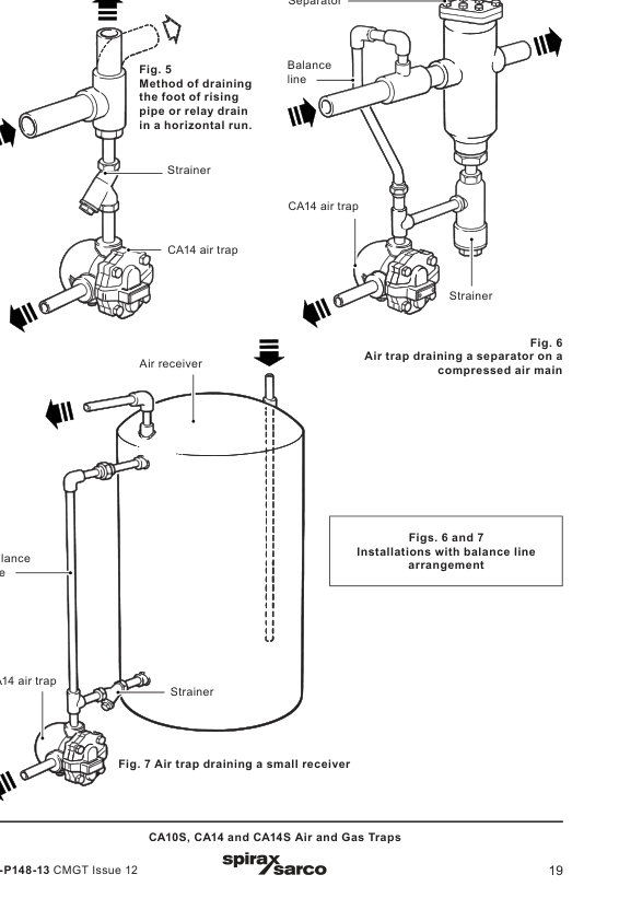
A balance line deserves particular attention in air-system drainage. The CA14 has no air bleed, which allows it to hold gas back when the float is down. Under a low drainage load, air in the body can normally be displaced as liquid enters. Under a high drainage load, such as aftercooler or receiver drainage, air may not be displaced through the inlet pipe and the trap can become air locked. The guide states that a separate balance line is then needed and that it is routed back to the upstream side. Whether it is required can depend on the installation, but where there is doubt the documented preference is to use the balance-line arrangement. The diagram in the installation section shows representative drainage applications.
Using CA14 in a drainage system
Common applications include draining the foot of a rising pipe, a relay drain in a horizontal run, a separator on a compressed-air main and a small receiver. In each case, the objective is the same: remove liquid as it arrives while limiting unnecessary gas discharge. The detailed piping arrangement may differ. A receiver or cooler with a heavy intermittent liquid load has a different air-lock risk from a simple low point in a main. Downstream pressure, a safe discharge destination and the practical provision for isolation, venting and maintenance access should be established in the project design rather than improvised at installation.
After installation or maintenance, the system must be checked for correct operation and any alarms or protective devices tested. The CA14 operating principle does not require adjustment by the user: liquid lifts the float and opens the main valve; gas lowers the float and closes it. If the product is used at its maximum permitted conditions, exposed surfaces may be hot. Personnel should isolate and safely vent pressure, allow the product to cool, assess the contents and surrounding environment, use appropriate protective equipment and follow the site's permit-to-work requirements. The installation information below retains these safety requirements in document form.
Maintenance, spares and ordering confirmation
The CA14 is designed so that servicing can be carried out in the pipeline when suitable isolation has been provided. Before any work, pressure must be isolated and safely vented, and the product allowed to cool. The CA14 maintenance procedure identifies replacement of the main valve cone and replacement of the complete valve-and-float assembly. Joint faces must be clean, a new cover gasket is used during reassembly, cover bolts are tightened uniformly to the stated torque, and the isolating valve is opened slowly before checking for leaks. The full procedure, spare-part lists and recommended torques are preserved in the installation guide section.
The CA14 uses a Viton component. If a Viton-containing product has been exposed to temperatures approaching 315 °C or higher, the material may have decomposed and formed hydrofluoric acid. The technical information directs personnel to avoid skin contact and inhalation of fumes and to dispose of Viton in the recognised manner described by the installation instructions. This is a specific safety condition, not a routine disposal note.
For an order or enquiry, identify the CA14 model, the selected connection type and standard, the size, the intended fluid duty and the required direction of flow for a flanged version. State any certification or inspection requirement when the order is placed; material certification to EN 10204 2.2 is available according to the technical data sheet. The local price reference contains exact CA14 whole-product records for 1/2 in and 3/4 in sizes only. Check the full operating envelope, connection requirement and installation arrangement with the detailed technical and installation information before releasing a final specification.
Description and intended use
CA14 is a range of float type automatic liquid drainers for air and gas systems. The body and cover are SG iron and the complete unit is readily maintainable. CA14 uses a Viton main valve cone.
CA14 is designed for use on air or gases within PED Group 2. It is not suitable for use on PED Group 1 liquids or gases. The product fully complies with the requirements of the European Pressure Equipment Directive 2014/68/EU.
Material certification to EN 10204 2.2 is available. State all certification and inspection requirements when the order is placed.
Sizes and pipe connections
1/2 in and 3/4 in screwed BSP T Rp (ISO 7-1) or NPT.
Materials
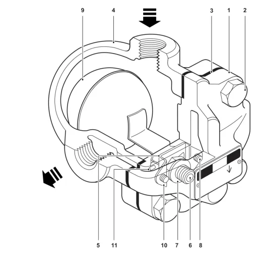
No. | Part | Material | Standard / grade |
|---|---|---|---|
1 | Body | SG iron | EN-GJS-400-15 |
2 | Cover bolt | Steel | BS 3692 Gr. 8.8 |
3 | Cover gasket | Reinforced exfoliated graphite | |
4 | Cover | SG iron | EN-GJS-400-15 |
5 | Main valve cone | Synthetic rubber | Viton |
6 | Main valve seat | Stainless steel | BS 970 431 S29 |
7 | Main valve seat gasket | Stainless steel | BS 1449 304 S11 |
8 | Main valve assembly screws | Stainless steel | BS 6105 Cl A270 |
9 | Ball float and lever | Stainless steel | BS 1449 304 S16 |
10 | Pivot frame | Stainless steel | BS 1449 304 S16 |
11 | Pivot pin | Stainless steel |
Pressure and temperature limits
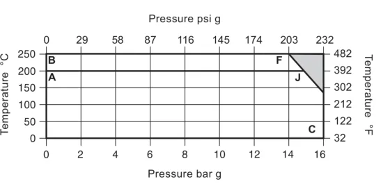
Body design conditions | PN16 |
|---|---|
PMA maximum allowable pressure | 16 bar g at 120 °C (232 psi g at 248 °F) |
TMA maximum allowable temperature | 250 °C (482 °F) |
Minimum allowable temperature | 0 °C (32 °F) |
PMO maximum operating pressure | 16 bar g (232 psi g) |
TMO maximum operating temperature, CA14 | 200 °C at 14.7 bar g (392 °F at 213 psi g) |
Minimum operating temperature | 0 °C (32 °F) |
DPMN minimum differential pressure | 0.1 bar (1.5 psi) |
Cold hydraulic test pressure | 24 bar g (348 psi g) |
CA14 is safe for use under full vacuum conditions.
Liquid specific gravity | 1.0 | 0.9 | 0.8 | 0.7 | Minimum 0.6 |
|---|---|---|---|---|---|
DPMX bar | 14.0 | 14.0 | 14.0 | 9.0 | 5.0 |
DPMX psi | 203 | 203 | 203 | 131 | 73 |
Capacity curve
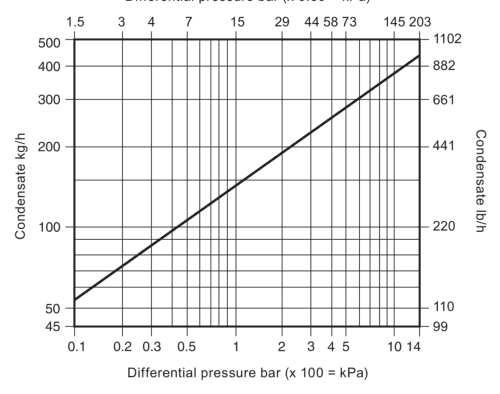
Dimensions and weight
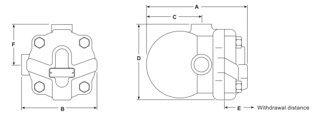
Size | A | B | C | D | E withdrawal distance | F | Weight |
|---|---|---|---|---|---|---|---|
1/2 in | 147 mm | 114 mm | 80 mm | 114 mm | 105 mm | 60.5 mm | 2.5 kg |
3/4 in | 147 mm | 114 mm | 80 mm | 114 mm | 105 mm | 60.5 mm | 2.5 kg |
Installation, disposal and maintenance information
Install CA14 with the flow direction shown on the body and with the float arm in a horizontal plane so that it rises and falls vertically. For complete details, use the Installation and Maintenance Instructions.
Viton disposal warning: if a Viton-containing product has been subjected to a temperature approaching 315 °C or higher, it may have decomposed and formed hydrofluoric acid. Avoid skin contact and inhalation of fumes. Dispose of Viton in the recognised manner stated in the Installation and Maintenance Instructions.
Spare parts and tightening torques
Available CA14 maintenance-kit items are cover gasket, main valve cone and float, main valve seat, main valve seat gasket, two main valve assembly screws, pivot frame and pivot pin. The CA14 seal kit contains the cover gasket and main valve cone. State the trap size and type when ordering spares.
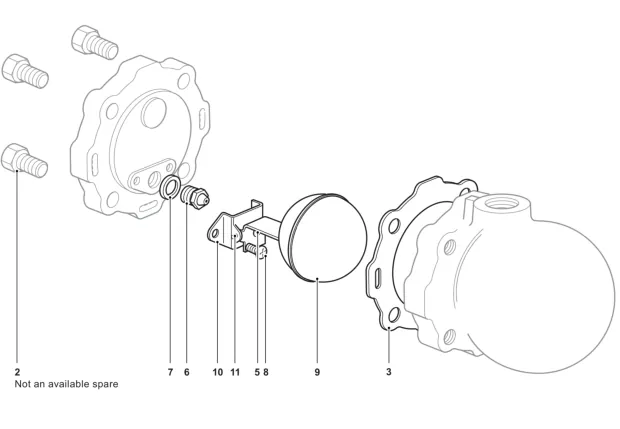
Item | Tool / size | Torque |
|---|---|---|
Cover bolt | 17 A/F, M10 x 30 | 47 - 50 N m |
Valve seat | 17 A/F | 50 - 55 N m |
Main valve assembly screws | Pozidrive, M4 x 6 | 2.5 - 3.0 N m |
Installation and Maintenance Guide
Safety information
Product information
Installation
Commissioning
Operation
Maintenance and spare parts
1. Safety information
Safe operation can only be guaranteed when CA14 is properly installed, commissioned, used and maintained by qualified personnel in accordance with these instructions. Follow the general installation and safety requirements for pipeline and plant construction and use appropriate tools and safety equipment.
Intended use and system checks
Refer to these instructions, the name-plate and the Technical Information Sheet to confirm suitability for the application.
CA14 is designed for Group 2 air or water/condensate duties. Check material suitability and the pressure and temperature limits. Provide a safety device if a malfunction could create an overpressure or overtemperature condition.
Determine the correct installation situation and direction of fluid flow. Remove protection covers from all connections before installation.
CA14 is not intended to withstand external stresses imposed by the system. The installer must assess those stresses and take precautions to minimise them.
Before work starts
Provide safe access, a guarded working platform where necessary, suitable lifting equipment and adequate lighting.
Consider pipeline contents, including flammable or hazardous substances and temperature extremes, and the surrounding environment, including explosion risk, oxygen deficiency, hot surfaces, fire, noise and moving machinery.
Consider the effect of isolation on the complete system. Open and close isolation valves gradually to avoid system shocks or disabling a protective device, control or alarm.
Isolate pressure and vent it safely to atmospheric pressure. Consider double block and bleed and the locking or labelling of closed valves. Do not assume the system is depressurised merely because a gauge reads zero.
Allow the product to cool after isolation. Use suitable protective clothing and comply with the site's permit-to-work procedure.
Residual hazards, disposal and returns
External surfaces can be hot and may exceed 250 C at maximum permitted operating conditions. CA14 may not be self-draining; take care during dismantling or removal. Protect non-self-draining products against frost where they may be exposed below freezing. Unless otherwise stated, the product is recyclable when disposed of with due care and under local regulations. When returning a product, provide written information about contamination residues or mechanical damage and the appropriate precautions.
2. CA14 product information
CA14 is a float-type automatic liquid drainer for air systems with an SG iron body and cover. It is readily maintainable and has a Viton valve cone. The selected scope includes 1/2 in and 3/4 in screwed CA14, plus DN15, DN20 and DN25 flanged CA14.
Configuration | Connections | Additional feature |
|---|---|---|
Screwed | 1/2 in and 3/4 in BSP T Rp (ISO 7-1) or NPT | Install with inlet at top. |
Flanged | DN15, DN20 and DN25; EN 1092 PN16, ANSI 150 or JIS/KS 10 | 1/2 in tapping for a balance line; specify R-L or L-R flow. |
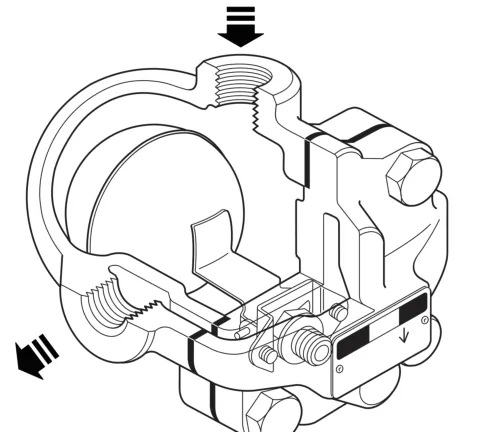
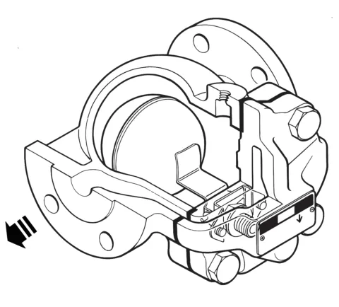
The cover can be drilled and tapped 3/8 in BSP T Rp (ISO 7-1) or NPT to fit a drain cock. The Installation and Maintenance Instructions cite TI-P148-36 for the screwed CA14 and TI-P148-12 for the flanged CA14 as the associated technical-information sheets. The following operating limits apply to CA14: PN16 body design; PMA and PMO 16 bar g at 120 °C (232 psi g at 248 °F); TMA 250 °C (482 °F); CA14 maximum operating temperature 200 °C (392 °F) at 14.7 bar g (213.15 psi g); minimum temperature 0 °C (32 °F); minimum differential pressure 0.1 bar; and maximum cold hydraulic test pressure 24 bar g (348 psi g). CA14 is safe under full vacuum conditions.
3. Installation
Before installation, observe the safety information and verify the materials and maximum pressure and temperature values. If the product maximum is lower than the system condition, include a device that prevents overpressurisation. Confirm the installation position and flow direction and remove connection protection covers.
Fit screwed CA14 in the horizontal plane with the inlet at the top so that the float mechanism is free to rise and fall vertically.
Fit flanged CA14 in the horizontal plane so that the float mechanism is free to rise and fall vertically. The selected CA14 flange configuration determines left-to-right or right-to-left flow.
Fit the trap below the point being drained and point the arrow on the name-plate downwards.
Where discharge is to atmosphere, arrange a safe discharge location because the discharged fluid may be at 100 °C (212 °F).
Balance-line arrangements
CA14 has no air bleed. At low loads, air in the body can be displaced as water enters. At high loads, such as cooler or receiver drainage, air may not be displaced through the inlet pipe, so a separate balance line is needed to avoid air locking. Pipe the balance line back to the upstream side. The need can only be determined from the installed system, but where there is doubt the guide recommends using the balance-line arrangement.
4. Commissioning
After installation or maintenance, ensure that the system is fully functional. Test alarms and protective devices.
5. Operation
CA14 is a continuous-discharge float trap that removes liquid from air and gas systems. As liquid enters the main chamber, the float rises and the attached lever opens the main valve, keeping the system drained. When air or gas enters, the float drops and closes the main valve tightly against the seat. A balance line is needed where it is required to prevent air lock. Float-type traps provide instantaneous load handling, clean tight shut-off and resistance to waterhammer and vibration.
6. Maintenance and spare parts
Observe the safety information before maintenance. The cover gasket contains a thin stainless steel support ring that can cause injury if it is not handled and disposed of carefully. With suitable isolation, repairs can be carried out with CA14 in the pipeline. Reassembly requires clean joint faces.
Replacing the CA14 main valve cone
Undo the cover bolts and lift off the cover. Withdraw the pivot pin to release the float and lever from the pivot frame.
Push out the main valve cone and replace it with a new one.
Reassemble and refit the cover using a new gasket.
Tighten cover bolts uniformly to the recommended torque. Open the isolating valve slowly until full system pressure is achieved and check for leaks.
Replacing the main valve assembly
Undo the cover bolts and lift off the cover.
Remove the complete float assembly by undoing the two assembly screws.
Remove the main valve seat and replace it with the new seat and gasket.
Fit the new float assembly and tighten its set screws to the recommended torque.
Refit the cover with a new gasket. Tighten cover bolts uniformly, open the isolating valve slowly and check for leaks.
Item | Tool / size | Recommended torque |
|---|---|---|
Cover bolt | 17 A/F, M10 x 30 | 47 - 50 N m |
Valve seat, screwed CA14 | 17 A/F, M12 | 50 - 55 N m |
Valve seat, flanged CA14 | 17 A/F, M12 x 12 | 50 - 55 N m |
Pivot frame assembly set screws | Pozidrive, M4 x 6 | 2.5 - 3.0 N m |
CA14 maintenance-kit items are the cover gasket, main valve cone and float, main valve seat, main valve seat gasket, two assembly screws, pivot frame and pivot pin. The CA14 seal kit contains the cover gasket and main valve cone. State the size and type of trap when ordering spares.