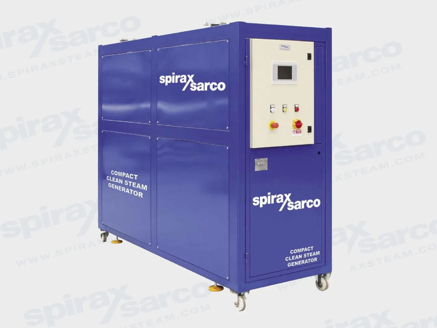
Clean steam generator packages produce high-quality steam from treated water using indirect plant-steam or electrical heating for sterilisation, humidification and other hygienic process duties.
Spirax Sarco clean steam generators for hygienic systems
A Spirax Sarco clean steam generator produces high-quality steam from suitably treated water while keeping the heating medium separate from the steam used by the process. The family is intended for duties in which steam quality affects sterilisation, product contact, humidification or process integrity. Depending on the selected package, plant steam or electrical power supplies the energy, while modulating pressure and level control keeps the generator aligned with changing demand. The result is a packaged source of clean steam that can be engineered into a healthcare, pharmaceutical, food, beverage, biotechnology, electronics or general hygienic utility.
Indirect generation matters because the plant steam used to transfer heat is not the steam delivered to the clean distribution system. Treated or demineralised feedwater is heated in the generator, and the generated steam leaves through the clean-steam side. This separation does not remove the need for water treatment, blowdown, sampling or downstream conditioning: contaminants in the feedwater, poor drainage, non-condensable gases and moisture carryover can still affect the final steam quality. Selection should therefore cover the complete route from water and primary steam through the generator, clean-steam outlet and point of use.
One family, several duty ranges
The page brings together several established package formats. They share the clean-steam objective, but they are not interchangeable models. The correct choice is set by required output, clean-steam pressure, available primary energy, feedwater conditions, application requirements and the space available for access and tube-bundle removal.
Family
Verified role
Reference range or duty
CSM-C
Compact plant-steam package, with optional pre-heating and degassing
165-640 kg/h at 3 bar g in current CB/CD data
CSM-E
Compact electrical package
Up to 150 kg/h at 3 bar g in the sales brochure
CSM-K
High-capacity plant-steam package with extractable tube bundle
Model guidance up to 3,800 kg/h
m-CSG
Ultra-compact indirect mini package
Nominal 300 or 600 kg/h
CSG-HS
Healthcare sterilisation package
Nominal 200, 550, 1,250 or 1,800 kg/h
The figures in this table are orientation points, not a promise that every pressure, connection, option or certification is available in every market. The technical sections below retain the source conditions and tables. A project specification must use the final selection sheet, nameplate and general arrangement drawing for the ordered unit.
Compact CSM-C and CSM-E packages
CSM-C is the compact plant-steam option for steriliser-grade clean steam. The current technical sheet covers 165 to 640 kg/h at 3 bar g for CB and CD configurations with a pre-heated water temperature of 80 deg C. Its generator vessel, clean-steam surfaces and treated-water surfaces are AISI 316L stainless steel. The package is supplied on a transportable frame, with a PLC controlling clean-steam pressure and water level and, where a pre-heat tank is fitted, its temperature and level. A colour touchscreen provides alarms and operating values. The optional pre-heating and degassing stage helps remove soluble gases before water enters the generator; the water quality and the actual operating pressure still need to be confirmed for the duty.
CSM-E uses electrical power rather than plant steam and is described in the official CSM brochure as a compact package up to 150 kg/h at 3 bar g. Because the selected source is a family brochure rather than a current model-specific technical sheet, this page does not invent additional CSM-E pressure, connection, material or installation limits. Buyers should request the current CSM-E selection and installation documentation with the quotation. Both CSM formats are suitable starting points for sterilisation, SIP, clean-room humidification, process heating and other high-integrity services when their energy source and output meet the site brief.
CSM-K for higher clean-steam demand
CSM-K extends the compact-generator concept into a high-capacity package. The official technical information lists model designations from 401 through 804 and output guidance from 260 to 3,800 kg/h at stated reference conditions. The reference table uses 10 bar g primary steam, 3.5 bar g clean steam and 20 deg C feedwater; changing those pressures or the water conditions changes the available output. The primary medium passes through an extractable AISI 316L tube bundle, allowing a planned route for inspection and cleaning. Secondary wetted parts are stainless steel, and the package includes PLC pressure and level control with automatic TDS and bottom blowdown options. The technical sheet gives maximum primary and clean-steam pressures of 12 and 7 bar g respectively.
CSM-K is intended for process applications, laundries, food and beverage plants, hospital sterilisers, laboratories, humidification and selected electronics, pharmaceutical and biotechnology duties. It is a large pressure package: the installation manual requires an indoor, level support structure capable of carrying the filled unit, safe lifting arrangements and clearance around and above the equipment. The plant steam, clean steam, feedwater, condensate, safety relief and blowdown interfaces must be planned from the selected drawing rather than from a generic catalogue dimension.
m-CSG ultra-compact clean steam generation
m-CSG is an indirect mini generator for projects that need a small footprint without abandoning packaged control and safety functions. The 300 and 600 sizes are rated at nominally 300 and 600 kg/h at 9-10 bar g primary steam, 3 bar g clean steam and 20 deg C feedwater. Its technical sheet gives a clean-steam operating limit of 5 bar g at 159 deg C and a primary limit of 12 bar g at 191.7 deg C. The unit is supplied on a metal base with a wired control panel, modulating pressure and level control, an extractable tube bundle, insulation, strainers and isolation valves. The generator body and tube bundle are AISI 316, with PTFE gaskets and AISI 304 supports.
Choose the H application when the duty is humidification, container sterilisation or general clean steam. Choose the F food-and-beverage version only when the required configuration and declaration cover the intended contact duty: the source documents describe EC 1935/2004 compliance and require an end-user cleaning-in-place cycle before first food-contact use. The output table includes combinations that are not recommended; an N/A cell is a selection boundary, not a missing quotation value. Feedwater pressure, pump choice, TDS control and the clean-steam pressure set point must be reviewed together.
CSG-HS for healthcare sterilisation
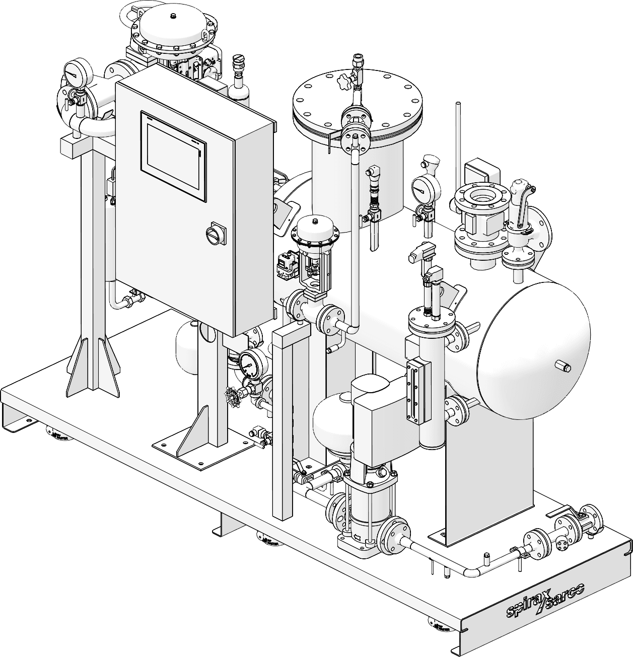
CSG-HS packaged arrangement from official technical information; the illustration is specific to the healthcare range.
CSG-HS is the healthcare-focused package. Its four nominal sizes, CSG-HS-020, -055, -125 and -180, are rated at 200, 550, 1,250 and 1,800 kg/h at the stated reference condition of 9 bar g primary steam, 4 bar g clean steam and 20 deg C feedwater. The current TI describes clean saturated steam up to 6 bar g and primary plant steam up to 12 bar g. The system is packaged with an onboard wired panel, modulating pressure and level control, intelligent PLC functions, automated start-up and commissioning, diagnostics and preventive-maintenance provisions. The documents describe performance exceeding EN 285 and ST79 and make clear that the exact declaration or certification options depend on geography and configuration.
CSG-HS uses indirect heat exchange, so plant steam does not mix with the generated clean steam. Demineralised or reverse-osmosis water is recommended for performance. The installation is indoors, with protection from freezing and enough access to remove the tube bundle and service the deaerator. The selection drawing controls the size-dependent DN or ANSI connections, safety-valve discharge, non-condensable-gas vent, drains, blowdown and sampling arrangement. The installation manual also requires a cleaning cycle, a site-acceptance check and a controlled PID-tuning sequence before the package is placed into normal service.
Steam quality is a system responsibility
A Spirax Sarco clean steam generator is one part of the hygienic steam route. Feedwater must be tested against the applicable quality requirements, and the generator must be protected from scale, contamination and excessive total dissolved solids. Blowdown and drainage need a safe destination; relief-valve and non-condensable-gas vents must discharge to a compliant safe area. Downstream pipework should be clean and correctly drained, and the final point of use may still need moisture separation, filtration or precise pressure control.
For downstream dryness, review the CS10 clean steam separator. Where particulate control is part of the quality plan, compare the CSF16 steam filter. When the clean-steam line needs point-of-use modulation, the Steritrol clean service control valve can be considered. The wider clean steam products range provides the surrounding traps, safety devices and hygienic pipeline equipment needed to complete the route.
What to confirm before ordering
Required clean-steam mass flow, normal and peak demand, pressure set point and allowable pressure variation.
Primary energy source, available plant-steam pressure or electrical supply, and any pneumatic actuator air requirement.
Feedwater source, treatment method, temperature, pressure, conductivity and expected total dissolved solids.
Application category: healthcare sterilisation, SIP, food or beverage contact, humidification, pharmaceutical, biotechnology, electronics or another validated clean duty.
Selected family and size, connection standard, safety-valve discharge, blowdown, sampling and non-condensable-gas vent route.
Required declaration, pressure-equipment category, food-contact documentation or local certification; these are configuration and geography dependent.
Downstream separation, filtration, pressure control, condensate drainage and steam-quality testing at the point of use.
For engineers selecting a Spirax Sarco clean steam generator, the most reliable order basis is the verified duty envelope plus the final project drawing, not a single headline capacity. The technical and installation information that follows preserves the family-specific tables, conditions and safety instructions so the selected package can be checked before it is connected or commissioned.
Scope and selection basis
This technical section combines the exact family documents for CSM-C, CSM-K, m-CSG and CSG-HS. CSM-E information is limited to the official CSM sales brochure because no current model-specific technical sheet was located. Values are reference data under the conditions stated in each source. Use the final selection sheet, nameplate and general arrangement drawing for the ordered package.
All indirect generators require suitably treated feedwater. Primary steam pressure, clean-steam pressure, feedwater temperature and feedwater pressure interact with output. A value in one table must not be reused as an unconditional rating for another family.
CSM-C steam compact clean steam generator
Source: TI-P486-04, TES Issue 4. The CSM-C provides steriliser-grade clean steam from suitably treated water using plant steam as the heating medium. It can be supplied with or without an integral feedwater pre-heating and degassing system. The current sheet covers 165 to 640 kg/h at 3 bar g for the pre-heated-water CB and CD configurations.
Pipework connections
Connection
Type
Size
Plant steam inlet
Flanged PN16
DN50
Clean steam outlet
Flanged PN16
DN50
Condensate return outlet
Flanged PN16
DN50
Condensate line drain
Flanged PN16
DN15
Feedwater
Flanged PN16
DN15
Vessel drain / blowdown
Flanged PN16
DN25
Air supply
Push fit for nylon tube
8 mm diameter
Safety valve discharge
Flanged PN16
DN50
Safety valve drain
Welded tube
1/2 inch diameter
Pre-heat tank overflow
Screwed tube
3/4 inch gas
Optional test point
Tri-clamp
1 inch
Versions and output at 3 bar g clean steam
Unit
Plant steam, bar g
Maximum clean steam, kg/h
CSM-CB with pre-heat tank
6 / 7 / 8 / 9
165 / 220 / 270 / 320
CSM-CD with pre-heat tank
6 / 7 / 8 / 9
330 / 440 / 540 / 640
These flow rates use pre-heated water at 80 deg C and allow for pressure drop across the steam inlet control valve. Values for units without a pre-heat tank and special pressure/flow combinations must be obtained from Spirax Sarco.
Pressure, temperature and materials
Side
Maximum operating pressure
Maximum operating temperature
Test pressure
Primary plant steam
10 bar g
184 deg C
21.7 bar g
Secondary clean steam
5 bar g
159 deg C
12.7 bar g
Part
Material
Pre-heat tank, vessel shell, heating coils
AISI 316L stainless steel
Clean steam pipework and feedwater pipework
AISI 316L stainless steel
Frame, plant steam and condensate pipework
Painted mild steel
Insulation
Glass fibre with fireproof synthetic-fibre jacket
Controls, options and dimensions
The PLC regulates clean steam outlet pressure, generator water level and, where present, pre-heat tank temperature and level. The colour touchscreen shows alarms and controlled parameters. Options include communication interfaces, remote supervision, TDS analysis, external compressor, electric control valves, EN 285/HTM 2031 sampling, stainless-steel frame or panels, transport wheels, automatic vessel blowdown and manual or automatic clean-steam outlet isolation.
Unit
A x B x C, mm
Dry mass, kg
Wet mass, kg
CSM-CA without tank
1880 x 790 x 2310
780
1340
CSM-CB with tank
1880 x 790 x 2310
800
1420
CSM-CC without tank
1880 x 790 x 2310
800
1400
CSM-CD with tank
1880 x 790 x 2310
850
1610
Keep at least 1000 mm clear at the front and rear for safe working access. Engineering drawings govern the installed connection positions.
CSM-E electrical compact generator
Source: SB-P486-02, CSM Compact Clean Steam Generator sales brochure. CSM-E uses electrical power and is described as a compact package with output up to 150 kg/h at 3 bar g. The brochure shows treated feedwater, a pre-heater and degasser where present, droplet separation and PLC control. Because no current exact CSM-E technical or installation sheet was found in the verified source set, connection sizes, detailed limits, materials and site utilities must be confirmed from the quotation and supplied documentation.
CSM-K high capacity clean steam generator
Source: TI-P486-08, CH Issue 1. CSM-K supplies steriliser-grade clean steam from treated feedwater using plant steam. The pressure vessel is manufactured to the cited pressure-equipment requirements, and the primary medium passes through an extractable tube bundle. Secondary wetted parts are stainless steel.
Model output guidance
Model
Output kg/h
Model
Output kg/h
CSM-K401
260
CSM-K402
320
CSM-K403
370
CSM-K501
500
CSM-K502
620
CSM-K503
700
CSM-K601
930
CSM-K602
1150
CSM-K603
1300
CSM-K604
1700
CSM-K702
1730
CSM-K703
2000
CSM-K704
2630
CSM-K802
2600
CSM-K803
2900
CSM-K804
3800
The table is based on 10 bar g primary steam, 3.5 bar g clean steam and 20 deg C feedwater. The published typical specification uses CSM-K704 to raise 2000 kg/h at 3 bar g when supplied with 8 bar g plant steam; this is an example specification, not a universal rating.
Design data and utilities
Item
Value
Maximum primary steam pressure
12 bar g
Maximum clean steam pressure
7 bar g
Tube sheet, tube bundle and shell
AISI 316L stainless steel
Primary header
Carbon steel
Support frame
Carbon steel
Insulation option
Rock wool with aluminium or 304 stainless-steel cover
Compressed air
6 bar g; optional compressor if unavailable
Electrical supply
400 V, 3-phase, 50 Hz; fused isolator near the unit
Control
PLC pressure and level control; automatic TDS and bottom blowdown options
Recommended feedwater is demineralised or reverse-osmosis quality, with analysis before installation and commissioning. Applications include process, laundry, food and beverage, hospital steriliser, laboratory, humidification, electronics, pharmaceutical and biotechnology duties.
m-CSG ultra-compact generation system
Source: TI-P486-20, TES Issue 5. m-CSG is an indirect mini clean steam generator supplied ready for installation. The 300 and 600 sizes are rated at nominally 300 and 600 kg/h at 9-10 bar g primary steam, 3 bar g clean steam and 20 deg C feedwater. The H version is for humidification, container sterilisation and generic clean steam. The F version is for food and beverage contact applications documented as EC 1935/2004 compliant.
Design and operating limits
Side
Design pressure
Design temperature
Operating boundary
Primary plant steam
12.8 bar g
194.4 deg C
Up to 12 bar g / 191.7 deg C
Clean steam
8 bar g
194.4 deg C
Up to 5 bar g / 159 deg C
Feedwater
8 bar g
110 deg C
Water pressure must suit the clean-steam set point; pump option available
Safety valve
Setting stated as 6 bar g
Maximum production table, kg/h
Cells show production at clean-steam pressures 5 / 4 / 3 / 2 / 1 bar g, in that order. A slash pair in the source represents the two feedwater-pressure conditions; N/A is not a recommended operating condition.
Size
Primary bar g
Production by clean pressure, kg/h
300
12
260 / 300-330 / 320-430 / N/A / N/A
300
10
180 / 250 / 320-330 / 320-420 / N/A
300
8
100 / 160 / 240 / 320-340 / 290
300
6
- / 75 / 140 / 230 / 290
300
4
- / - / - / 120 / 210
600
12
490-540 / 500-660 / 500-700 / N/A / N/A
600
10
490 / 500-660 / 500-700 / 470-730 / N/A
600
8
270 / 440 / 500-600 / 470-730 / 510-650
600
6
- / 200 / 380 / 470-520 / 510-650
600
4
- / - / - / 310 / 430
Maximum production excludes blowdown. For a unit with a pump, use the source table's pump-condition value. The final selection must use the actual water pressure, pump arrangement and TDS/blowdown requirement.
Dimensions, connections and materials
Size
L x W x H, mm
Tube-bundle extraction clearance
Empty / operating / maximum mass, kg
300
1472 x 860 x 1615
950 mm
350-400 / 430-480 / 520-570
600
1945 x 905 x 1800-1950
1050 mm
450-500 / 600-650 / 700-750
Connection
300
600
Clean steam outlet
DN50 PN16
DN80 PN40
Feedwater inlet
DN15 PN16
DN20 PN16
Generator drain
DN25 PN16
DN25 PN16
Plant steam inlet
DN32 PN16
DN50 PN16
Condensate outlet
DN25 PN16
DN25 PN16
TDS discharge, optional
DN15 PN40
DN15 PN40
The generator body and tube bundle are AISI 316, the primary head is carbon steel, tube-bundle/body gaskets are PTFE and mounting supports are AISI 304. Digital regulators or PLC logic maintain pressure and level; the panel provides emergency stop, local/remote start and cumulative alarm functions.
CSG-HS clean steam generation system for healthcare
Source: TI-P663-01, TES Issue 12. CSG-HS is designed for healthcare sterilisation and uses plant steam as the primary heating medium. All systems are packaged and ready to install. The indirect heat exchanger keeps primary steam separate from generated clean steam.
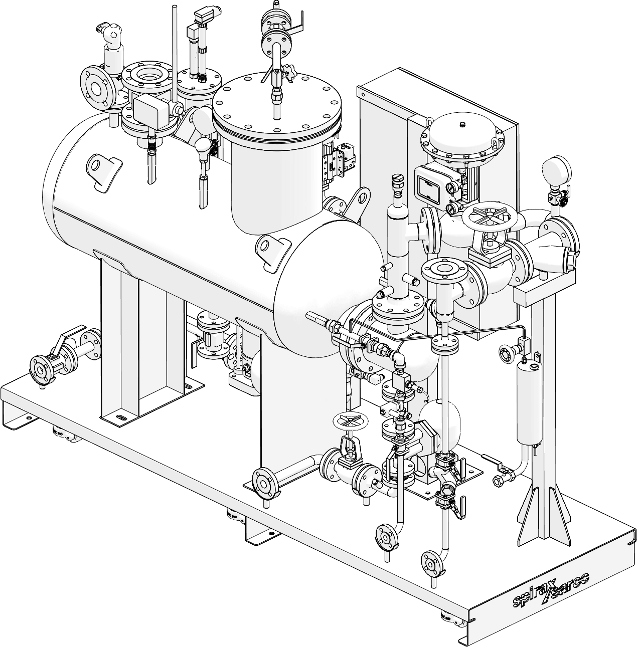
Alternate CSG-HS package view from the official technical information.
Range and reference condition
Model
Nominal production
Reference primary steam
Reference clean steam
Reference feedwater
CSG-HS-020
200 kg/h
9 bar g
4 bar g
20 deg C
CSG-HS-055
550 kg/h
CSG-HS-125
1250 kg/h
CSG-HS-180
1800 kg/h
Design and maximum operating conditions
Item
Value
Primary design pressure / temperature
12.8 bar g / 194.4 deg C
Secondary design pressure / temperature
8 bar g / 194.4 deg C
Feedwater design pressure / temperature
8 bar g / 110 deg C without pump; 8 bar g / 100 deg C with pump
Maximum clean steam
Saturated steam up to 6 bar g / 165 deg C
Maximum primary steam
Plant steam up to 12 bar g / 191.7 deg C
Minimum supply pressure
At least clean-steam pressure plus 0.5 bar g; see installation manual
Minimum ambient and installation
0 deg C minimum; indoor installation only; protect from freezing
Maximum clean steam production with feedwater at 20 deg C
Each cell gives production at clean-steam pressures 4.5 / 4.0 / 3.5 bar g. Plant steam pressure is the row variable.
Model
Plant 8 bar g
Plant 9 bar g
Plant 10 bar g
CSG-HS-020
137 / 170 / 207
180 / 214 / 250
220 / 254 / 292
CSG-HS-055
370 / 456 / 548
480 / 566 / 666
583 / 677 / 788
CSG-HS-125
823 / 996 / 1213
1044 / 1254 / 1490
1292 / 1516 / 1627
CSG-HS-180
1134 / 1417 / 1750
1501 / 1818 / 2162
1884 / 2210 / 2542
Dimensions and weights
Model
Standard L x W x H, mm
Tube extraction clearance
Maximum operating mass, kg
020
2000 x 850 x 1850
1250 mm
980
055
2350 x 850 x 1850
1300 mm
1340
125
2450 x 1450 x 2060
1600 mm
1900
180
2950 x 1450 x 2065
2000 mm
2450
EnEV 100 mm insulation changes the maximum package dimensions and mass; the source table lists 020 2500 x 950 x 1975 mm/1200 kg, 055 2750 x 1100 x 2050 mm/1500 kg, 125 2550 x 1450 x 2200 mm/2100 kg and 180 3100 x 1500 x 2240 mm/2500 kg. Dimensions are maximums for the stated configurations.
Connections, controls and options
Connection
020
055
125
180
Plant steam inlet, metric
DN32 PN16
DN50 PN16
DN80 PN16
DN100 PN16
Condensate outlet, metric
DN25 PN16
DN25 PN16
DN40 PN16
DN40 PN16
Clean steam outlet, metric
DN50 PN40
DN80 PN40
DN125 PN16
DN150 PN16
Feedwater inlet, metric
DN15 PN40
DN20 PN40
DN25 PN40
DN32 PN40
TDS blowdown, metric
DN15 PN40
DN15 PN40
DN15 PN40
DN15 PN40
Sampling system
1/2 inch BSP with 6 mm sample connection, size/configuration dependent
Construction features include modulating pressure and level control, an intelligent PLC with SIMS technology, a wired panel, automated start-up/commissioning, system diagnostics and preventive-maintenance support. Insulation, feedwater pressurisation, TDS control, sample cooling, valves, communications and frame/cabinet material are configurable options. Available declarations and certifications are geography and configuration dependent.
Important scope and safety notice
This section is a structured visitor-facing extraction of the selected Spirax Sarco installation and maintenance manuals. It preserves the safety boundaries and the sequence logic needed to understand the package. It is not a replacement for the current manual supplied with the ordered unit, the component manuals, the nameplate, the wiring diagram or the local pressure and electrical regulations.
Qualified personnel only. Installation, commissioning, operation and maintenance must be performed or supervised by competent personnel trained for steam, hot water, pressure equipment, electricity and the installed control system. Read all supplied manuals before work starts.
Identify the exact model, serial number, nameplate limits, design drawing and document set before connecting services.
Isolate primary steam, clean steam, feedwater, condensate, pneumatic air and electrical power before installation or maintenance.
Safely vent residual pressure to atmosphere and allow hot surfaces and water to cool. A zero gauge reading is not proof of depressurisation.
Wear suitable protective clothing and use a permit-to-work and lockout procedure where required by the site.
Route safety-valve, blowdown, drain and non-condensable-gas discharges to safe, compliant destinations. Never block or intercept a relief path.
Use suitable lifting equipment and lift from the approved base or lifting points only. Leave access for tube-bundle, deaerator and control-panel maintenance.
Keep clean-steam connections capped until the connection is ready. Do not introduce dirt, scale, incompatible gaskets or construction debris into the clean side.
CSM-C installation and maintenance
Source: IM-P486-05, CSM-C Steam Compact Clean Steam Generator Installation and Maintenance Instructions. CSM-C packages are intended for indoor use on a level support capable of carrying the filled unit. The manual recommends at least 1000 mm of clear access at the front and rear. Site-specific drawings govern the connection positions and any lifting or seismic provisions.
Installation sequence
Inspect the delivered package, nameplate, pressure components, control cabinet, documentation and protective covers. Do not install a damaged or non-conforming unit before it is reviewed.
Clean and blow through connecting pipework so foreign material or scale cannot enter the feedwater or clean-steam sides.
Connect the treated feedwater supply to the feedwater inlet and provide an upstream manual isolation valve, kept closed until installation is complete.
Connect the generated clean-steam outlet to the clean distribution line and provide a downstream manual isolation valve, kept closed until installation is complete.
Pipe the pressure safety valve to a suitably sized safe vent and drain. The discharge must comply with local standards and must not expose personnel or equipment to released steam.
Connect primary plant steam, condensate return and drains. Use clean-steam-compatible flanges, sanitary connections and gaskets where specified.
Connect the pneumatic supply, typically 6 bar g, and the electrical supply according to the supplied wiring diagram. Electrical work is for qualified electricians.
Connect the vessel bottom blowdown and any pre-heat tank overflow or sample points. Blowdown can flash to steam and must be safely piped.
Verify grounding, isolation valves, relief routes, instrument connections, pipe supports, insulation and access before commissioning.
Commissioning and operation
After a safety officer or responsible competent person has checked all connections, open treated-water isolation gradually and confirm the displayed tank and generator levels. Reset any expected low-level alarm, verify the feedwater pump direction where fitted, and check the pre-heat tank temperature and level. Introduce primary steam slowly, observe the programmed tank temperature and generator pressure, and open the clean-steam outlet gradually once the operating set point is reached. Confirm alarms, automatic isolation and the clean-steam route before accepting load.
For a planned stop, close primary steam and treated-water isolation, allow pressure to fall, close the clean-steam outlet and condensate isolation as directed by the manual, and protect the package against freezing. Emergency stop or abnormal conditions require isolation of primary steam, feedwater and clean steam followed by safe venting and competent investigation.
Maintenance focus
Check primary and clean-steam pressures daily and investigate abnormal changes.
Maintain feedwater quality and adjust blowdown frequency to the water and TDS condition. Blowdown must discharge safely.
Inspect the safety valve, drains, traps, control valves, level instruments, temperature probe and pressure transmitter at the intervals in the supplied schedule.
Use the manual cycle and maintenance sections for pump purging, valve inspection, gasket replacement and component-specific work. Re-test after work before returning to service.
CSM-K installation and maintenance
Source: IM-P486-10, CSM-K High Capacity Clean Steam Generator Installation and Maintenance Instructions. CSM-K is a large pressure package. The unit is for indoor use unless the design specification states otherwise and needs a level support capable of carrying the filled weight. Provide at least one metre of clearance around and above the unit, plus the tube-bundle extraction and service space shown on the approved drawing.
Transport and connection planning
Assess the route, lifting plan, floor loading, access platform, ventilation, lighting and protection from weather or freezing before unpacking.
Inspect the vessel, frame, valves, instruments, control cabinet, safety equipment and supplied component manuals. Confirm that the configuration matches the design specification.
Connect feedwater, generated clean steam, the selected energy source, energy-source return or condensate, safety/pressure-relief discharge and drains.
Install manual isolation valves and strainers where specified. Provide clean-steam check and isolation valves, primary-steam isolation and trap sets as required by the installation.
Connect the 6 bar g compressed-air supply where pneumatic controls are fitted and the 400 V 3-phase 50 Hz electrical supply through a correctly rated fused isolator.
Support external pipework independently so no external stress is transferred to the generator nozzles. Check flange alignment and bolt torque.
Start-up, shutdown and maintenance
Before start-up, close the manual isolation valves, verify that all lines are drained or vented, confirm the relief system and safety controls, and check that the clean-steam and water sides meet the nameplate conditions. Open services slowly in the sequence specified by the supplied manual, establish feedwater level, introduce the energy source, confirm pressure and level control, and then bring the clean-steam outlet onto the process gradually. Do not bypass trips, high-pressure protection, low-level protection or relief devices.
For shutdown, isolate the energy source and feedwater, allow the package to depressurise and cool, isolate the clean-steam and condensate outlets and drain only through the approved routes. Maintenance includes inspection of the vessel, tube bundle, valves, traps, gauges, safety system, control components and gaskets. Use genuine replacement parts and re-test pressure, control and safety functions before returning the unit to service.
m-CSG installation, food-contact cleaning and maintenance
Source: IM-P486-21, m-CSG Ultra-compact Clean Steam Generation System Installation and Maintenance Instructions. The package is installed indoors and must be protected from freezing. Lift it from the base using suitable equipment. The exact connection positions, support details and clearances come from the general arrangement drawing.
Connections and pre-commissioning
Inspect the frame, generator, control panel, instruments, protective covers and documentation. Check the model, version H or F, pressure settings and required utilities.
Connect the clean-steam outlet, feedwater inlet, generator drain, primary plant-steam inlet, condensate outlet, safety-valve discharge and optional TDS/sample connections.
Use clean, supported pipework and suitable gaskets. Install the clean-steam isolation valve downstream and a check valve when generators operate in parallel.
Connect electrical power and, where fitted, instrument air between 3 and 15 bar g. Verify grounding, emergency stop, local/remote start and cumulative alarm wiring.
Check the safety valve discharge and bottom blowdown routing. Blowdown is at generated-steam pressure and temperature and must not be returned to feedwater or condensate.
Flush construction debris from the connected lines, confirm water and primary-steam design conditions, and verify that the downstream system can accept the safety-valve setting.
Commissioning and control logic
Open services gradually, prime the feedwater line and introduce primary steam through the heating ramp. The pressure regulator or PLC modulates the primary valve from the clean-steam pressure signal; the level regulator or PLC modulates feedwater. High pressure, low level, high level, loss of air and power failure interlocks close or restrict the relevant valves. TDS control and blowdown must be set to the feedwater and generator water condition.
For the F food-and-beverage version, complete the end-user cleaning-in-place cycle before the first food-contact application and retain the declaration of conformity and contact-material list. This cleaning step is not optional packaging guidance; it is part of the documented food-contact boundary.
Normal stop and maintenance
Close primary steam, allow pressure to fall, drain or blow down through the approved route, close feedwater and other isolations and protect the system against frost. Follow the manual for regulator checks, valve and trap inspection, level and pressure instrumentation, TDS calibration and component replacement. After maintenance, confirm that the pressure relief path, interlocks, cleanliness and operating set points are restored.
CSG-HS healthcare installation and commissioning
Sources: TI-P663-01, TES Issue 12, and IM-P663-02, TES Issue 11. CSG-HS must be installed indoors, with an ambient temperature above 0 deg C and protection from freezing. The package requires access for tube-bundle and deaerator extraction. Size 020 and 055 are lifted from the base with a forklift or transpallet; sizes 125 and 180 use the lifting eyes installed on the base frame. Never lift from the vessel, pipework, cabinet or another component.
Pre-installation checks
Complete the document review and site-acceptance checks. Confirm the nameplate, model, pressure/temperature design data, selected options and the supplied P&ID.
Verify that the foundation, lifting method, lighting, access platform, pipe supports and maintenance clearances are suitable.
Connect size-specific primary steam, condensate, clean-steam, feedwater, safety-valve, non-condensable-gas vent, drain, TDS blowdown and sampling lines from the approved drawing.
Ensure the primary steam and feedwater lines are pressurised only within the design data and are drained or vented before start-up. Confirm the clean-steam downstream design is not below the unit or safety-valve rating.
Connect electrical power, earth and any pneumatic actuators according to the wiring diagram. Use qualified electricians and maintain the control-panel IP rating.
Keep the clean side protected from contamination. Use only materials and tools that do not compromise the required steam cleanliness.
Cleaning and on-site commissioning
The package is supplied after a pickling and passivation cycle, but installation can introduce dirt into pipework. Complete the documented cleaning cycle to flush the feedwater line and generator before normal production. During the site-acceptance and commissioning sequence, check filters, manual isolation valves, drains, safety-valve piping, grounding, sensors, flange torque and any optional condensate cooler or integrity-test equipment.
Close manual steam, condensate, clean-steam and feedwater isolations while checking that all connected services are available and critical alarms are clear.
Open the required condensate, drain, vent, feedwater and non-condensable-gas paths. Prime the feedwater line and check the pneumatic positioners where fitted.
Power the control panel, select the documented first-start sequence and enter the correct clean-steam pressure and water-level set points.
Run the first cleaning cycle, introduce plant steam gradually, and follow the HMI instructions. Repeat an integrity test if a leak is detected.
Use the PID tuning sequence to simulate high and low demand, complete the tuning confirmation and verify stable pressure and water level before opening the process outlet.
Operation, shutdown and maintenance
The PLC maintains clean-steam pressure through a pressure PID loop and primary-steam control valve and maintains water level through a level PID loop and feedwater valve. Automated start-up raises the water level, opens configured isolation valves, verifies temperature and pressure and ramps to set point. Automated shutdown reduces the level and steam set point, closes the primary supply and stops water control after the documented temperature condition is reached.
For a planned outage, isolate primary steam, feedwater, clean steam and condensate, vent and drain safely and protect the unit from freezing. Check the TDS limit, blowdown route, non-condensable-gas vent, filters, control valves, sensors, safety devices, insulation and the condition of the clean side at the intervals in the supplied service schedule. A change in operating pressure can require recalibration of the expansion vessel, feedwater and steam valve trims, sensors and PID settings; do not simply change the set point without the manual's recalibration checks.
Discharge warning. Bottom blowdown and non-condensable-gas vents can release fluid at generated-steam pressure and temperature. Route them to safe destinations with no back pressure and comply with current legislation before operation.
Clean steam generation is only one part of the hygienic steam chain. Downstream control, filtration, separation and sanitary protection still shape final steam quality.